Table of Contents
Advertisement
Advertisement
Table of Contents

Subscribe to Our Youtube Channel
Related Manuals for Detnov CAD-250


Summary of Contents for Detnov CAD-250
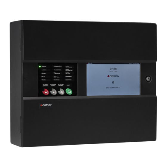
- Page 1 INSTALLATION GUIDE...
- Page 4 Revision control Revision Comment Date First edition 29/11/2019 Typographical errors and regulatory references 05/12/2019 Specification table corrections and graphical corrections 16/12/2019 Lay out remake and revision 16/06/2020...
-
Page 5: Standards And Compliance
If these criteria are not met, the control panel may be damaged, problems may arise during system start-up or the functioning of the system may be adversely affected. The CAD-250 control panel is certified to work under certain conditions; exceeding the working ranges of the control panel or inadequate conditions can lead to the warranty being voided. -
Page 6: Table Of Contents
CONTENTS 1. INTRODUCTION ................8 1.1. ABOUT THIS MANUAL ............8 1.3. DISCLAIMER ................8 1.3. STANDARDS AND COMPLIANCE .........5 1.4. ADDITIONAL INDICATIONS ...........9 1.5.GENERAL SAFETY WARNINGS ..........9 1.6. REQUIRED DOCUMENTATION AND DESIGN ......10 1.7. EXPLICIT DEFINITIONS ............10 1.8. MAIN FEATURES OF THE CONTROL PANEL ......11 1.9. - Page 7 6. MAINTENANCE ................58 3.9. SOUNDER OUTPUT ..............34 3.9.1. Cancelling sounder outputs ............34 6.1. LOG ..................58 3.9.2. Checking the sounder line ............34 6.2. PERIODIC TESTS ..............58 3.9.3. Polarised sounder connection .............35 6.2.1. Test Mode ..................58 3.9.4. NON-polarised sounder connection..........35 6.3. CLEANING ................59 3.10.
-
Page 8: Introduction
KEEP THE BOX. It contains a printed template to descriptions regarding procedures and technical details necessary to facilitate assembly. You may need the packaging to carry out the assembly, connection and start-up of CAD-250 fire alarm send the control panel to the technical service or to control panels. -
Page 9: Additional Indications
2012/19/EU (WEEE), European standard on the recycling of non-disposable products, such as The installation of the system on CAD-250 control panels must unclassified municipal waste within the area of the include a method to isolate or disconnect the input voltage European Union. -
Page 10: Required Documentation And Design
The definitions are classified according to the following levels: to install. Word Definition Detnov pays special attention to the compatibility of the components and the integrity of the system components in the long term; however, ⚠WARNING! Risk of personal injury check any compatibility notes between versions to ensure the greatest reliability and the best user experience. -
Page 11: Main Features Of The Control Panel
1.9. ARCHITECTURE The CAD-250 is an addressable control panel with advanced The modular design of the CAD-250 control panel allows up to 3 configuration and functional features, designed to work with DETNOV modular components to be combined in a single structure of up to 4 addressable sensors, modules and addressable butto. - Page 12 System composition 1 x CAD-250 1 x CAD-250 + 1 x CAD-250LBLED Each option of the main control panel or expansion control panels includes: Main board, which provides the following options: • 2 monitored sounder outputs • 2 voltage-free relay outputs on the board •...
- Page 13 Network system composition Architecture with TMB-250 network card. RS485 standard communication. max. 1000 m Up to 64 nodes max. 1000 m max. 1000 m Architecture with TMB-250FI-250 network card. Communication via single-mode fibre cable. max. 1000 m Up to 64 nodes max.
-
Page 14: Inspection
Check that the equipment contains the following: Ref. Units Description Contents CAD-250 Addressable control panel Accessories bag Keys If the control panel is damaged or any of these elements are missing, do not continue with the installation and contact your distributor. -
Page 15: Requirements
1.11. REQUIREMENTS If the zone to be protected is a classified area affected by directive 94/9/EC, ATEX, be sure to design the installation and use equipment 1.11.1. Assembly notes that meets the classification requirements. KNOWLEDGE: Make sure you have the necessary mechanical and electrical knowledge to assemble this panel on the wall and implement Danger of electric shock. -
Page 16: Assembly Guide
The control panel has two rectangular cuts in the lower area on the 2.1. CABLE ENTRIES right and left sides. These entries are practical if you are using a The CAD-250 has various cable entries. The entry covers can be conduit to guide the cables. removed easily using pliers. -
Page 18: Attachment
2.2. ATTACHMENT The CAD250 control panel's cardboard packaging contains a printed template that allows the fixing holes to be made in the wall STEP 1 and the positioning of the control panel to be checked easily. It will also prevent you from having to hold the control panel to carry Remove template out this task. - Page 19 4x WALL 4x LAG SCREWS, 5.5 mm x 40 mm PLUGS PHILLIPS/POZIDRIVE ROUND HEAD 452 mm DNP8 (8 mm) step 3 398 mm step 4 step 2...
-
Page 20: Connection Guide
To open the door, you will need to unlock its lock. Use the keys supplied 6 BATTERY CONNECTOR with the CAD-250 control panel (see page 10). When you connect the battery cable terminal, make sure this The person responsible for the facility must know where these keys connector has a specific connection position;... -
Page 22: Insertable Language Card
3.2. INSERTABLE LANGUAGE CARD The CAD-250 control panel is prepared to operate in different languages, regardless of the internal language configuration of the control panel software, with a language card package supplied with the control panel. Using these language cards, you can customise the language of the LEDs and PRIMARY CONTROLS (see sections 3 and 4.2), which, once installed, show the text associated with each LED and each CONTROL through transparent windows. -
Page 23: Main Board Protection
3.3. MAIN BOARD PROTECTION To remove the MAIN BOARD protection, follow the steps below: 1. Locate the MAIN BOARD protection (see previous page). 2. Loosen the 4 screws that retain the protection using a Phillips screwdriver. 3. Move the protection UP slightly and PULL to remove it. It is not necessary to remove the screws that secure the MAIN BOARD protection. -
Page 24: Main Board
3.4. MAIN BOARD Item Ref. Description Comment Item Ref. Description Comment Jumper for Buzzer off. Disconnects the LOOP CARD Loop input, output and mesh internal buzzer ONLY in case of a SYSTEM connection. They are assembled FAULT. from left to right. Up to 4 cards Jumper for Earth Leakage Detection. - Page 25 3. CONNECTION GUIDE 3.4 Main board LOOP CARD LOOP CARD LOOP CARD LOOP CARD POSITION 1/2 POSITION 3/4 POSITION 7/8 POSITION 5/6 JP32 ⏚ OFF BUZZER FAULT SYSTEM ON OFF NET RS485 SND2 0.5A SND1 0.5A 24V Aux SND1 SND2 R.Alarm R.Fault ⏚...
-
Page 26: Connecting To The Mains
Although the consumption of the CAD-250 control panel is not too high, it is important to install a double pole differential to prevent short circuits. To connect the CAD-250 to the MAINS, carry out the following steps: step 2 1. Remove the fuse holder. -
Page 27: Connecting The Batteries
Once the control panel is started (see section) with the batteries connected, the control panel will check the status of the batteries. If For the CAD-250 control panel to operate correctly, it uses two 12 the test is not correct, the message ‘BATTERY FAULT’ will appear V lead-acid batteries connected to each other in series, providing a on screen. -
Page 28: Loop Cards
To install a loop card on the CAD-250 control panel, carry out the following steps: Make sure you are not wearing any metal accessories (rings, bracelets, etc.) that could short circuit the electronics and take the appropriate antistatic precautions for handling the loop card. - Page 29 3. CONNECTION GUIDE 1. Locate the position for the loop card(s). 2. Insert the card into the slots starting with the one marked LOOP CARD POSITION (1/2). 3. Fix the card using the screws included with it. 4. Make the necessary connections (see section 3.7). 5.
-
Page 30: Addressable Loops
3.8. ADDRESSABLE LOOPS Each loop card can support up to 250 DETNOV addressable devices (sounders, input/output modules, isolators or detectors). In general, all of these devices are powered by the loop itself. It is possible to subdivide each loop into multiple zones without exceeding the total number of zones of 2000. -
Page 31: Loop Continuity
3.8.1. Loop continuity The loop wiring must be implemented as a closed loop, therefore it is essential to ensure the return of the loop line to the control panel. Only connect the return of the earth connection to the control panel, never to an external earth connection. -
Page 32: Addressable Loop
3.8.3. Addressable loop The following illustration shows the typical connections of addressable and conventional equipment in an addressable loop: INPUT MODULE RELAY CONVENTIONAL SOUNDER MODULE 270k CONVENTIONAL ZONE 100k 24 V power supply ISOLATOR BASE WITHOUT ISOLATOR BASE WITH ISOLATOR Before connecting the panel or the equipment, check the continuity and isolation of each loop using a low voltage multimeter. -
Page 33: Loop Check
4. Use a multimeter to check that there are no 3.8.4. Checking the loop leakages between the screen cable and the positive To check the loop wiring, WITHOUT CONNECTING THE LOOP TO (+) of the cable or the negative (-) of the cable. THE CONTROL PANEL, carry out the following steps: STEP 4 Leakages between... -
Page 34: Sounder Output
3.9. SOUNDER OUTPUT NET RS485 SND2 0.5A SND1 0.5A The MAIN BOARD has two sounder outputs. The sounder circuits are 24V Aux SND1 SND2 R.Alarm R.Fault ⏚ ⏚ NO NC C NO NC C INTERNAL designed to operate with an end-of-line resistor (by default). RS485 step 1 3.9.1. -
Page 35: Polarised Sounder Connection
NET RS485 SND2 0.5A SND1 0.5A 3.9.3. Cancelling sounder outputs 24V Aux SND1 SND2 R.Alarm R.Fault ⏚ ⏚ NO NC C NO NC C ⏚ INTERNAL RS485 If you are going to use addressable sounders connected to the loop and you are not going to use the sounder outputs on the MAIN BOARD, carry out the following steps: 1. -
Page 36: Auxiliary Output
JP32 3. CONNECTION GUIDE ⏚ OFF BUZZER FAULT SYSTEM ON OFF 3.10. 24 V AUXILIARY OUTPUT LOOP CARD LOOP CARD 24 V auxiliary output The MAIN BOARD has a 24 V AUXILIARY OUTPUT. This output can N 3/4 POSITION 5/6 POSITION 7/8 supply, for example, current to an external relay: NET RS485... -
Page 37: Final Connection Checks
3.13. FINAL CONNECTION CHECKS 3.13.1. Use of ferrites Before connecting the control panel to the mains network, make sure It is not normally necessary to use ferrites with the CAD-250 control you check the following points: panel. 1 LOOP CONTINUITY: Check the loop continuity with a voltmeter... - Page 38 3.14. COMMUNICATIONS CARD (Optional) CONVENTIONAL RS485 RS485 RS232 ANALOGUE The CAD-250 control panel permits the installation of two network card MODBUS 1 MODBUS 2 MODBUS 1 TX RX versions. Ref. Description Network card for loop connection on CAD-250 TMB-252 control panels via isolated RS485 port for network...
- Page 39 3. CONNECTION GUIDE step 3 2. Locate the network card connector on the main board. See entry 28 in the table in section 3.4. 3. Secure the board with the 5 screws provided. 4. Connect the expansion cable, supplied with the network card, to step 4 the main board connector.
- Page 40 The accepted maximum length between nodes with standard cable is 1000 m. The architecture of networked control panels of the CAD-250 control panel must be a continuous loop; this is a requirement that may also be The use of standard shielded cable is only accepted for data with a required by national or local regulations, e.g.
- Page 41 CONVENTIONAL CONVENTIONAL CONVENTIONAL CONVENTIONAL CONVENTIO CONTROL PANEL 1 CONTROL PANEL 2 CONTROL PANEL 3 S485 RS485 RS485 RS232 RS485 RS485 RS232 RS485 RS485 RS232 RS485 RS485 RS232 RS485 RS232 RS485 RS485 RS232 ANALOGUE ANALOGUE ANALOGUE ANALOGUE ANALOGUE MODBUS 1 MODBUS 2 MODBUS 1 MODBUS 1 MODBUS 2...
-
Page 42: Start-Up
SERVICE Permanent battery voltage is less than 20 V. SYSTEM Amber Only available on CAD-250-P: It allows you to obtain a There is a power supply issue caused by the PRINTER FAULT Intermittent paper copy of the system's events. This device cannot be network, batteries or fuses installed as an option. -
Page 43: Primary Controls
4.4. INITIAL START-UP Colour/ Condition Description status If you followed the initial steps of this guide, a GREEN LIGHT will light up on the left part of the door (MAIN PANEL) and the screen will show: POWER SUPPLY Amber Critical system fault. In this case, the system is not FAULT Permanent operative. -
Page 44: Quick Control Panel Configuration
5. QUICK CONTROL PANEL CONFIGURATION This screen will remain provided if the system does not detect any event (alarm, fault or technical event). The purpose of this section is to carry out a simple initial start-up by configuring basic parameters for both the control panel and the Touch the touchscreen with your finger over the padlock icon (��). -
Page 45: Administrator Screen
5.2. ADMINISTRATOR SCREEN The administrator screen is divided into 6 different sections: No. Name Posit. Description MAIN MENU Left Categorises the sections. Loops - Sectors - Manoeuvres - Log - Network - Configuration - Engineering - Maps Right SUBMENU Classifies the options for each menu section. It is different for each section. -
Page 46: Configuration
5.3. CONFIGURATION 5.3.3. Installer information SETTINGS (Main menu) > GENERAL (Submenu) > MISCELLANEOUS (Tab) In this section, you will be able to establish basic configuration parameters for the control panel. To access these settings, press: This information will be shown in the EVENT MANAGER when a FAULT SETTINGS (Main menu) >... -
Page 47: Loop Autosearch
5.4. LOOP AUTOSEARCH When starting the system up for the first time, it should recognise the devices installed in the loops. You can perform this action automatically via the LOOP AUTOSEARCH feature. LOOP (Main menu) > AUTOSEARCH (Submenu) Main Menu Submenu Main View Use the cursors to view all of the devices found... -
Page 48: Devices
5.5. DEVICES Until you manually enter the devices in the system or you carry out an autosearch, the device list will appear empty. In this submenu, you can configure the devices connected to a loop individually. From the navigation bar and with the help of the buttons, LOOP (Main menu) >... -
Page 49: Information And Configuration Of The Devices
5.5.1. Device information and configuration Descriptive term Definition From the device list and when selecting one of them, you will have DEVICE Identified by the loop number and physical address of the device. access to its detailed fields, which will allow you to consult or configure The device description is also shown here when it is assigned. -
Page 50: Sectorisation
5.6. SECTORISATION The modes establish the behaviour according to a hierarchical structure whereby the AREA is superior to the ZONE and this is superior to the DEVICE. From the SECTORISATION section on the main menu, it is possible to create, review and modify the sectorisation tree. The behaviour due to the WORKING MODE of an AREA will affect the ZONES and the DEVICES of each one, but this does not happen the other way round. - Page 51 The following elements are identified on the segmentation tree: When selecting a zone line, the pop-up menu will allow you to view: Field Definition ENTITY Area, Zone or individual device DESCRIPTION Alphanumeric definition assigned for each entity. Up to 54 characters.
-
Page 52: Manoeuvres
5.7. MANOEUVRES From the new manoeuvre management window, press: A manoeuvre can be defined as a set of actions that are programmed +ADD (Lower navigation bar) on a control panel based on the statuses taken by the system, areas, zones or devices. Status changes are called events, and an action will be linked to each event, such as the activation of sounders, relays, etc. - Page 53 In the new ENTITY EVENT floating Once the entity has been selected, the ENTITY EVENT window will be window you can configure the shown again and new available fields will appear. following fields TYPE It allows you to select the type of trigger event, such as fault or COUNTER alarm but also what kind of device will shot the action.
- Page 54 A floating window will let you select between EVENT ACTION. On this occasion, press ACTION. Once the entity is selected, the ENTITY floating window, software will return you to the ACTION, will be available with the ENTITY ACTION window and will following options: show new available fields.
-
Page 55: Software Update
5.8. SOFTWARE UPDATE 2. To update the FIRMWARE press INSTALL FROM USB. One of the easiest ways to update the CAD-250 is via the USB TYPE A port using a PEN DRIVE. Make sure that the PEN DRIVE is formatted as FAT32; it is not necessary for it to be empty. -
Page 56: Panel Test
If the chosen facility contains various panels, you will be able to choose A window will ask you to confirm the FIRMWARE update. between the panels that comprise it. 6. Press the FIRMWARE button. 4. Press the Panel 1 button (1). 5.9. -
Page 57: Ethernet Port Configuration
This submenu allows you to establish the basic parameters for network DHCP (MANUAL/AUTO): Define whether the assignment of the control panel operation of the CAD-250 control panel. To access the CONNECTIVITY IP address is manual or automatic. Check with your submenu, press: network administrator for the type of IP assignment of your connection. -
Page 58: Maintenance
6. MAINTENANCE 6.2.1. Test Mode To carry out maintenance tasks, you must change the working mode 6.1. LOG of the zone or area where you are going to do the maintenance to According to the recommendations of the UNE 23007 Part 14 standard, TEST MODE;... -
Page 59: Cleaning
6.3. CLEANING Press on the MODE drop-down menu and select TEST The control panel must be cleaned regularly with a soft cloth dampened with water. Do not use solvents Note that in the device TREE, the MODE field of the device (1.1) has changed to "T". -
Page 60: Troubleshooting
7.1. FAULTS SHOWN ON THE PRIMARY CONTROLS The LEDs and primary controls of the CAD-250 control panel allow the user to know the status of the facility quickly and to initiate a series of actions easily. These LEDs normally indicate anomalies in the detection network or control panel. - Page 61 LEDS CAUSE SOLUTION SERVICE (Green) Switched on whenever the control panel is operating and powered. If there is no power or it is out of service, the LED will switch off. ALARM (Red) Switched on whenever an event or alarm is detected. Switched off if the control panel has no alarm event.
-
Page 62: Events Screen
7.2. EVENT SCREEN Name Description If an event occurs in the facility, the STANDBY SCREEN will change to It shows if there is an active alarm, according to the EN54-2 standard. ALARM BAR It includes a zones in alarm counter; the first zone in alarm and the the EVENT SCREEN. - Page 63 Name Description Name Description List filters according to status. On the right side of the screen there is a column of navigation icons Each icon includes a counter that indicates the number of active events for each status. It allows access to higher user and configuration levels The icon is highlighted when the counter shows 1 or more alarms.
- Page 64 Under the FAULTS icon in the EVENT SCREEN, the different system faults are shown. Below is a list of errors, causes and solutions for each of them: DEVICES CAUSE SOLUTION This fault is due to the lack of end-of-line monitoring of some devices with this feature. Replace the end-of-line monitoring or change the switch and do not OPEN FAULT For example, the input modules where monitoring mode can be configured with a switch.
- Page 65 LOOPS CAUSE SOLUTION The control panel detects that there is an earth leakage and the option Check and correctly connect the power supply. EARTH FAULT FACILITY > LOOP > EARTH FAULT and JUMPER JP7 are activated. Power supply fault Check the power input fuse, the position of the electrical protection MAIN POWER FAULT element lever and/or the mains power supply.
-
Page 66: Technical Specifications
8. TECHNICAL SPECIFICATIONS This fire control panel was designed, manufactured and certified in The CAD-250 control panel was designed, manufactured and certified in accordance with the subsections of the following European standards: accordance with the subsections of the following European standards:... - Page 67 LOOP OUTPUTS DIMENSIONS: Maximum measurements of the 421 x 55 mm on the back control panel (in mm): OUTPUT VOLTAGE: 26 Vdc to 33 Vdc (Detnov protocol) EXPANSION 2 (upper and lower) INPUTS: measuring 50 mm x 15 mm MAXIMUM LOAD: 0.45 A...
-
Page 68: Annex 1: Totem Installation
ANNEX 1: TOTEM INSTALLATION One of the main features of the CAD-250 control panel is its expansion capacity, thanks to the possibility of modular assembly, which offers the user a completely flexible system. It is possible to create an assembled set in the form of a tower of 2, 3 or 4 control panels. - Page 69 The support consists of two work planes: Firstly, fit the support to the lower control panel, taking into account that the screen of the MASTER control panel (the control panel that has the · The front plane, through which the cables that will enter the control touchscreen) must be at a height of approximately 1.5 m from the floor panel located at this level will run.
- Page 70 On the FRONT PLANE of each support, starting from the left, fit the Once the cables that go to the lower control panels are fitted, fit the necessary ties for the zone line cables that will enter the control panel cable lines that will enter the control panel installed at the current level, at each level.
- Page 71 Continuing with the previous example, in the event of installing a tower or totem of 3 control panels with 4 zones per control panel, the wiring layout will be as follows REAR PLANE: FRONT PLANE: · On the upper level, LOOP ·...
- Page 72 If you are planning to include link cables between the different sections or cabinets through an additional cabinet, also remove the expansion and lower fixing these holes. Each expansion cabinet (CAD-250-B and CAD- covers. 250-BLED) is supplied with two connection cables.
- Page 73 5. Now fit the lower control panel first, support it on the lower brackets Repeat the process with the control panel that goes immediately of the support and fix it to the bolts of the support using the M6 nuts above it.
- Page 74 7. Install each loop card that corresponds to each cabinet as LOOPS LOOPS LOOPS LOOPS LOOP CARD LOOP CARD 1 and 2 3 and 4 5 and 6 7 and 8 indicated in sections 3.7 and 3.8. POSITION 5/6 POSITION 7/8 LOOP CARD LOOP CARD LOOP CARD...
- Page 75 7: Follow the installation steps from page 24 to 50, taking into account that: Only the SOUNDER, ALARM and FAULT outputs of the CAD-250 control panel are monitored, although it does not occupy the upper part. For the CAB-250B or CAB-250BLED expansion cabinets, it is not necessary to provide output wiring for the SND1, SND2, R.FAULT and R.ALARM outputs, as they do not have any function.
-
Page 76: Annex 2: Compatible Devices And Consumption
ANNEX 2: Compatible devices and consumption Standby Alarm External Address Reference Type Isolator Description consumption consumption power supply DTD-210A THERMAL.D 0.3 mA 3 mA Addressable thermovelocimetric detector DTD-215A THERMAL.D 0.3 mA 3 mA Addressable high temperature heat detector DOD-220A OPTICAL.D 0.3 mA 3 mA Addressable optical detector... - Page 77 Standby Alarm External Address Reference Type Isolator Description consumption consumption power supply MAD-421-I 0.3 mA 1.5 mA Addressable 1-input monitor and control module with isolator. MAD-422 0.3 mA 1.5 mA Addressable monitor and control module with 2 relay inputs and 2 relay outputs MAD-422-I 0.3 mA...
- Page 78 Standby Alarm External Address Reference Type Isolator Description consumption consumption power supply MAD-481 0.3 mA 1.5 mA Addressable control module with 1 voltage-free relay input of 240 Vac and 5 A. MAD-490 0.3 mA Isolator module PAD-10 INDICATOR 0.625 mA 2.5 mA Addressable remote indicator T P L D - 1 0 0...
-
Page 79: Annex 3: Autonomy And Loop Calculation
For this, Detnov provides a calculation tool that will facilitate this task for you in the design. In any case, we have included the theoretical basis of calculation so that you can check that your system will comply with the installation requirements. - Page 80 You can use the calculation tool available on our website, following the indications in this section and the recommendations of the UNE 23007-14 standard The system autonomy must be: Standby autonomy (h) After this time, it should be capable of supplying power for at least 30 min. It is accepted if there is local or remote monitoring of the system, and there is a maximum repair contract of 24 hours.
- Page 84 CAD-250_MI_372_en_2019 d MI 375 en 2020 c...
Need help?
Do you have a question about the CAD-250 and is the answer not in the manual?
Questions and answers