Table of Contents
Advertisement
Ellard Product Instructions
Motor Controller - V3D Maxi
Stock Code
V3D (Maxi) Motor Controller
00144
The installation should only be carried out by competent
!
personal and in accordance with current legislation
Please read the instructions carefully prior to installation
Description
Roundthorne Ind Est
Floats Road
Wythenshawe
Manchester M23 9WB
Tel: +44 (0) 161 945 4561
Fax: +44 (0) 161 945 4566
Iss: 1
INS
Doc No:
V3D Maxi
Advertisement
Table of Contents

Related Manuals for Ellard V3D Maxi


Summary of Contents for Ellard V3D Maxi
- Page 1 Ellard Product Instructions Roundthorne Ind Est Floats Road Wythenshawe Motor Controller - V3D Maxi Manchester M23 9WB Tel: +44 (0) 161 945 4561 Fax: +44 (0) 161 945 4566 Description Stock Code Iss: 1 V3D (Maxi) Motor Controller 00144 Doc No:...
- Page 2 LCC V3D (Maxi) Contents 1) Features and Specification........................ 1.1 V3D Board Layout........................1.2 V3D Layout in Standard Enclosure with Emergency/Stop and Membrane Push Buttons ..1.3 Installation and operation ......................1.4 DIP Switch's and Functions ..................... (1.4.1) Dead man / Impulse Operation (1.4.2) Emergency Closing (1.4.3) GO Function...
- Page 3 1) Features and Specification The LCCV3D (Maxi) Controller is designed with limited capabilities to operate an industrial door safely under electrical control by means of a push button or key-switch control Its intended use is to be connected to a suitable motor not exceeding the maximum load for the controller Connections are provided for Mains supply, Motor power, Mechanical or Electronic travel limits, External Push Buttons, Pneumatic, Electrical or Optical Safety Edge, Photocell, 24vDC aux power (100mA).
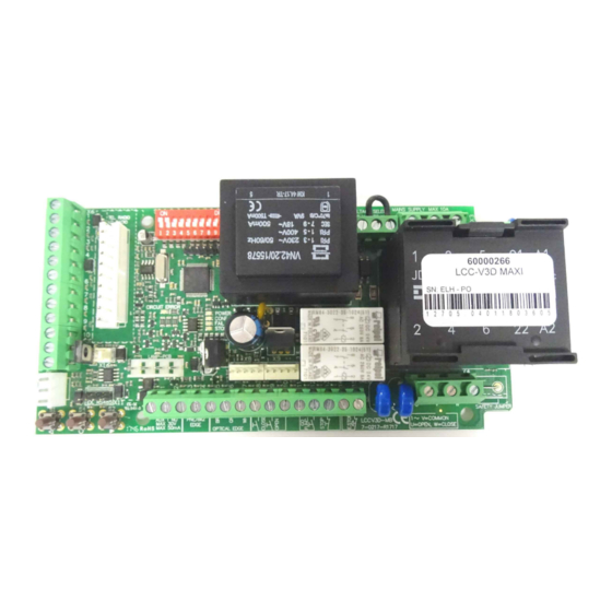
- Page 4 (1.1) V3D Board Layout LCC V3D Mini Basic (Full version) PCB VERSION 7-0217 R1717 Version -SOFTWARE _V02_03 PCB Dimensions 175 x 85 mm (L x W) MECHANICAL LIMIT CONNECTION OPEN ON BOARD CONTROL STOP TELECO BUTTONS RADIO RECEIVER CONNECTION CLOSE DIP Sw TRAFFIC LIGHT FUNCTION...
- Page 5 (1.2) V3D layout in Standard Enclosure (01098) with Emergency Stop Button (00119) and Menbrane Pushbutton (00105) 3 x 20mm Cable Glands...
- Page 6 (1.3) Installation and Operation 1. This Controller should be mounted in a suitable enclosure with a minimum IP 54 rating or suitable rating for the environment and should be: a) Vertically mounted and free from vibration b) Not exposed and free from dust and debris c) Fitted with appropriate cable glands to maintain the IP rating of the enclosure selected d) Fitted with appropriate wall fixings use to secure the unit...
- Page 7 (1.4.3) GO function By connection of a single N/O push button into the 'GO function' terminals the unit will now operate in the following sequential mode each time the button is pressed - OPEN - CLOSE - OPEN Operation starting with door Door at fully CLOSED position Door travels to OPEN limit - No stop possible Press 1 From fully open position door travels in the CLOSE direction...
- Page 8 9 10 POWER CONF/SER FAIL STOP...
- Page 9 (2.1.3) Connection for 415v (3ph) motor (Phase1) (Phase 2) (Phase 3) Typical 3 wire 3ph motor MOTOR EARTH Note: The motor EARTH wire must be connected to the main PE terminal (2.1.4) Connection for 230v (1ph) 3 wire motor (open) Common (close) (com)
- Page 10 (White) 9 10 POWER CONF/SER FAIL STOP...
- Page 13 9 10 POWER CONF/SER FAIL STOP...
- Page 14 9 10 POWER CONF/SER FAIL STOP...
- Page 15 9 10 POWER CONF/SER FAIL STOP...
- Page 16 (2.6) Connection for Traffic Light Card Traffic Light power must be provided by an Independent Notes power supply When using the flashing light (+) or (L) feature- only use LED type lamps (-) or (N) Power supply for lamps MAX 230Vac /24Vdc (+) or (L) Fuse rating 2A GREEN...
- Page 18 (2.8) Service Counter Th e V3D incorporates an in built counter that registers how many operations the door has performed This counter is not pre-settable, it is a counter only and can only be read using the LED indicators at a periodic service interval that is agreed by the installer To read the service counter proceed as follows: Send door to full close position then press OPEN and CLOSE simultaneously then release Observe the number of flashes of the (yellow) STOP and (red) FAIL LED's...
- Page 19 (3.0) LED Indication - Trouble shooting Green - 'POWER' LED The Unit has power Constant Mains power to PCB Yellow - 'CONF/SER' LED Constant Service counter reached Reset service counter Confirming of learning process Flashes once learning process has been completed 1 sec Flash Red - 'FAIL' LED If safety device has failed when CLOSE push button is pressed...
- Page 21 Ellard Ltd Ellard House Floats Road Roundthorne Ind Est Wythenshawe, Manchester M23 9WB Tel: +44 (0) 161 945 4561 Fax: +44 (0) 161 945 4566...
Need help?
Do you have a question about the V3D Maxi and is the answer not in the manual?
Questions and answers