Advertisement
Table of Contents
- 1 Table of Contents
- 2 Mains Supply Connection
- 3 Tube Motor Connection
- 4 Volt Free Connection for 'F' 'W' and 'SD' Series Operator
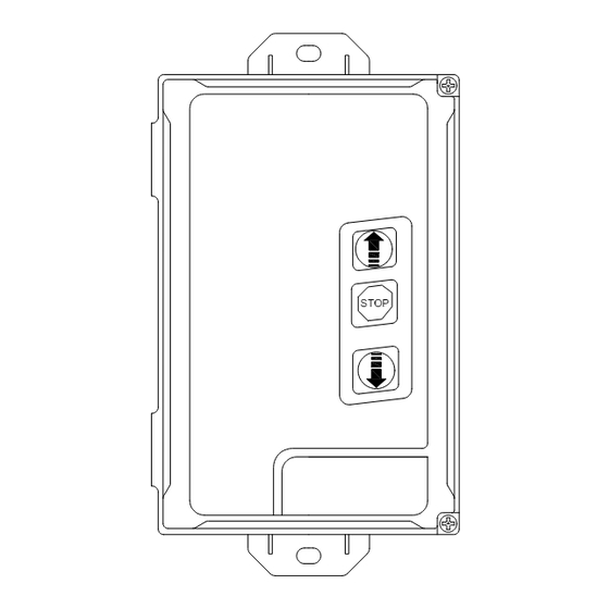
- 5 Emergency Stop Button Connection
- 6 8.2K Resistive Safety Edge Connection
- 7 Pneumatic Safety Edge Connection
- 8 Pre-Warning Light Connection
- 9 Red / Green Traffic Light Connection
- 10 230V Courtesy Light Connection
- 11 Radio Receiver / Transmitter - Deleting
- 12 Closing Delay Timer Settings
- 13 Trouble Shooting
- 14 Technical Data
- Download this manual
Advertisement
Table of Contents

Related Manuals for Ellard DC2


Summary of Contents for Ellard DC2
- Page 1 DC2 Controller (Quick Start Guide) STOP elec\DC2\book\20040\002...
-
Page 2: Table Of Contents
Trouble shooting Technical data Important Information This booklet is a quick start guide for 'ellard' products, it is no way intended as a direct replacement of the manufacturers manual All safety information and regulations are contained within the manufacturers manual should be veiwed before installation. - Page 3 DC2 general connections Closing Delay Timer Setting Connector For Run Timer Plug in Radio Receiver Settings Transmitter Programming Indicator Connection For Function (RED) Plug in 24v dc Settings Courtesy Light Safety Module P r o g I I P r o g I...
-
Page 4: Mains Supply Connection
Mains Power Connection EARTH (Grn/Yel) LIVE (Brown) NEUTRAL (Blue) Use these terminals as a direct connection for 230v (1ph) Mains supply to the DC2 Controller This connection should be fused at 13A (max) 230V Mains Supply 230v Tube Motor Connection... -
Page 5: Volt Free Connection For 'F' 'W' And 'Sd' Series Operator
Volt free Connection for 'F' , 'W' and SD series operators Connection COMMON Remove factory fitted link OPEN DIRECTION DWN = CLOSE DIRECTION Use these terminals as a direct connection to control 'F', 'W' and 'SD' series operators UP DWN Jumper Links 'ODM' and 'CDM' must be removed from the operator PCB Yellow... -
Page 6: Emergency Stop Button Connection
Remote Push Button Control Remote Impulse Button (If required) (If required) DIP1 DIP1 Remove factory fitted link and connect Push Button Station Common Connect a N/O single Push Button Stop Station Open Operating sequence Close OPEN - STOP - CLOSE - STOP Emergency Stop Button (If required) DIP1... -
Page 7: 8.2K Resistive Safety Edge Connection
8.2k Resistive Safety Edge Optical Safety Edge P r o g I I P r o g I P r o g I I P r o g I DIP3 DIP3 DIP1 DIP1 Note: Wire colour may vary Brown Brown Green White White... -
Page 8: Pre-Warning Light Connection
Pre-warning Light 230V Courtesy Light P r o g I I P r o g I P r o g I I P r o g I DIP3 DIP3 DIP Switch 4 (prog I) = ON DIP Switch 5 (prog I) = ON Light is continuously on when the Light flashes for 5 seconds before operator is running, light will switch... -
Page 9: Radio Receiver / Transmitter - Deleting
DC2 controller, scroll through the display to the location to be deleted Press and hold the programming button T1 the DC2 will bleep twice this location is now empty Repeat as necessary Once transmitters have been deleted DIP switch 5... -
Page 10: Closing Delay Timer Settings
P r o g I I P r o g I Run Timer Settings (DIP Switch 'RT') DIP4 DIP3 DIP switch 3 (prog I) = ON 52" 100" 148" 7" 55" 103" 151" 10" 58" 106" 154" 13" 61" 109" 157"... -
Page 11: Trouble Shooting
Trouble shooting - Common Faults Display Fault Check Mains Fuse Blank -No Power PCB Fuse Mains Power Supply Factory Fitted Link Emergency Stop Activated Release E-Stop Button DIP Switch Position Factory Fitted Resistor Safety Edge Activated Wiring or Loose Connections Repalce sensors DIP Switch Position Photocell Activated... - Page 12 Ltd Roundthorn Ind Est Dallimore Road Wythenshawe Manchester M23 9NX Tel: 0161 945 4561 Fax: 0161 945 4566...
Need help?
Do you have a question about the DC2 and is the answer not in the manual?
Questions and answers