Vega VEGAPOINT 31 Operating Instructions Manual
Capacitive level switch, transistor with io-link
Hide thumbs
Also See for VEGAPOINT 31:
- Operating instructions manual (52 pages) ,
- Operating instructions manual (56 pages)

Related Manuals for Vega VEGAPOINT 31


Summary of Contents for Vega VEGAPOINT 31
- Page 1 Operating Instructions Capacitive level switch VEGAPOINT 31 Transistor with IO-Link Document ID: 62325...
-
Page 2: Table Of Contents
Preparations ........................30 Connecting ........................30 Sensor parameter adjustment ..................31 Setup with PC/notebook (Bluetooth) ................... 32 Preparations ........................32 Connecting ........................32 Sensor parameter adjustment ..................33 10 Diagnostics and servicing ....................34 VEGAPOINT 31 • Transistor with IO-Link... - Page 3 13.1 Technical data ........................ 40 13.2 IO-Link ........................... 42 13.3 Dimensions ........................48 13.4 Industrial property rights ....................50 13.5 Hash function acc. to mbed TLS ..................50 13.6 Trademark ........................50 Editing status: 2019-10-23 VEGAPOINT 31 • Transistor with IO-Link...
-
Page 4: About This Document
Symbols used Document ID This symbol on the front page of this instruction refers to the Docu- ment ID. By entering the Document ID on www.vega.com you will reach the document download. Information, note, tip: This symbol indicates helpful additional infor- mation and tips for successful work. -
Page 5: For Your Safety
During work on and with the device, the required personal protective equipment must always be worn. Appropriate use The VEGAPOINT 31 is a sensor for point level detection. You can find detailed information about the area of application in chapter "Product description". Operational reliability is ensured only if the instrument is properly used according to the specifications in the operating instructions manual as well as possible supplementary instructions. -
Page 6: Eu Conformity
USA and Canada. Safety instructions for Ex areas For Ex applications, only devices with corresponding Ex approval may be used. Observe the Ex-specific safety instructions. These are an integral part of the operating instructions and are enclosed with every device with Ex approval. VEGAPOINT 31 • Transistor with IO-Link... -
Page 7: Product Description
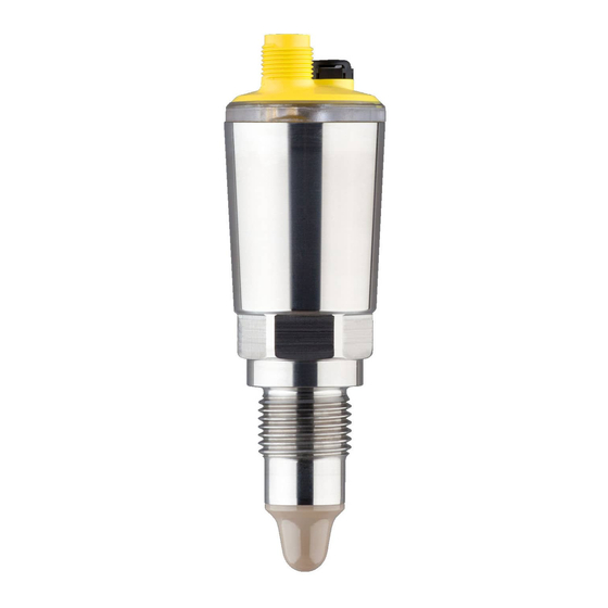
This operating instructions manual applies to the following instrument instructions versions: • Hardware version from 1.0.0 • Software version from 1.0.0 Constituent parts The VEGAPOINT 31 consists of the components: • Housing with integrated electronics • Process fitting • Plug (optional) Fig. 1: VEGAPOINT 31... -
Page 8: Principle Of Operation
Enter serial number manually in the VEGA Tools app (available free of charge in the respective stores) Principle of operation Application area The VEGAPOINT 31 is a capacitive point level sensor for point level detection It is designed for industrial use in all areas of process technology and can be used in light-weight, fine bulk solids. -
Page 9: Adjustment
3 Product description Typical applications are overfill and dry run protection. Due to its sim- ple and robust measuring system, the VEGAPOINT 31 can be used in almost all powdery bulk solids. Function monitoring The electronics module of VEGAPOINT 31 continuously monitors the following criteria via frequency generation: • Failure of the signal generation •... -
Page 10: Packaging, Transport And Storage
Unless otherwise indicated, the packages must be stored only under the following conditions: • Not in the open • Dry and dust free • Not exposed to corrosive media • Protected against solar radiation • Avoiding mechanical shock and vibration VEGAPOINT 31 • Transistor with IO-Link... -
Page 11: Accessories
Various threaded and hygienic sockets are available for devices with socket threaded version. You can find further information in the "Technical data" Protective cover For devices with dust Ex approval, the housing must be protected against external damage. Use the optional protective cover for this purpose. VEGAPOINT 31 • Transistor with IO-Link... -
Page 12: Mounting
Chemical properties of the medium • Abrasion and mechanical influences Switching point In general, VEGAPOINT 31 can be mounted in any position. The instrument must be mounted in such a way that the sensor is at the height of the requested switching point. Fig. 4: Installation examples 1 Upper level detection (max.) as overflow protection... -
Page 13: Mounting Instructions
Place the protective cover around the device housing as shown in the following illustration and fasten the two halves with the screws provided (1 Nm/0.74 lb ft). VEGAPOINT 31 • Transistor with IO-Link... - Page 14 4 Mounting Fig. 5: Mounting of the protective cover Protective cover - 1. half Protective cover - 2. half Fixing screws (2 pieces) VEGAPOINT 31 VEGAPOINT 31 • Transistor with IO-Link...
-
Page 15: Connecting To Power Supply
The instrument is connected with standard four-wire cable. If electro- magnetic interference is expected which is above the test values of EN 61326-1 for industrial areas, screened cable should be used. • M12 x 1 plug VEGAPOINT 31 • Transistor with IO-Link... -
Page 16: Connecting
Fig. 7: Wiring plan M12 x 1 plug - Transistor output, three-wire Voltage supply PNP switching NPN switching Contact, plug connector Function/Polarity Voltage supply/+ Transistor output 2 Voltage supply/- Transistor output 1/IO-Link Switch-on phase After switching on, the device first carries out a self-test in which the function of the electronics is checked. VEGAPOINT 31 • Transistor with IO-Link... - Page 17 5 Connecting to power supply • Internal check of the electronics • LED illuminated on the device lights "red - yellow - green" The current measured value is then output on the signal cable. VEGAPOINT 31 • Transistor with IO-Link...
-
Page 18: Access Protection
If this document is lost, the emergency device code can be retrieved from your personal contact person after legitimation. The storage and transmission of the device codes is always encrypt- ed (SHA 256 algorithm). VEGAPOINT 31 • Transistor with IO-Link... -
Page 19: Storing The Codes In Myvega
"PINs and Codes". This greatly simplifies the use of additional adjust- ment tools, as all Bluetooth access and device codes are automati- cally synchronized when connected to the "myVEGA" account VEGAPOINT 31 • Transistor with IO-Link... -
Page 20: Setup
This can be smartphones/tablets with iOS or Android operating system or PCs with PACTware and Bluetooth USB adapter. The following functional descriptions apply to all adjustment devices (smartphone, tablet, laptop …). VEGAPOINT 31 • Transistor with IO-Link... - Page 21 100 % Signalling NAMUR NE 107 Fault Switching output Yellow Operating status Green Access protection Bluetooth access code See supplementary sheet "PINs and Codes". Protection of the parameterization Deactivated Reset Units Temperature unit °C Only for "User-defined" application VEGAPOINT 31 • Transistor with IO-Link...
-
Page 22: Parameter Adjustment
• Uncovered • Covered • With buildup User-defined If you have selected the application User-defined you can adjust the switching states with the original medium or with the actual covering state. Only DTM adjustment VEGAPOINT 31 • Transistor with IO-Link... - Page 23 Only when the reset point (RP) is reached does the output switch back. If the measured variable moves between switching and reset point, the state of the output does not change. VEGAPOINT 31 • Transistor with IO-Link...
- Page 24 Window High (FH) and Window Low (FL). If the measured variable leaves the window, the output returns to its previous state. If the measured variable moves within the window, the state of the output does not change. VEGAPOINT 31 • Transistor with IO-Link...
- Page 25 Switching delay (DS1) The switching delay (DS) extends the reaction time until the sensor is switched over when the sensor tip is covered. You can enter a delay time from 0 to 60 seconds. VEGAPOINT 31 • Transistor with IO-Link...
- Page 26 • Maintenance required - green flashing Individual signalling If you have selected "Individual signalling", you can select the respec- tive LED colour for the switching states "Failure", "Switching output" and "Operating condition" separately in the following menu items. VEGAPOINT 31 • Transistor with IO-Link...
- Page 27 Sensor status • Status outputs • Parameter modification counter The display "Device status" provides an overview of the current status of the device. If fault messages or other information are available, a corresponding message is displayed here. VEGAPOINT 31 • Transistor with IO-Link...
- Page 28 First select the desired switching output and start the simulation. Then select the desired switching state. • Open • Closed Click on the button "Accept simulation value". The sensor now switches to the desired simulation switching status. VEGAPOINT 31 • Transistor with IO-Link...
- Page 29 Hardware version • Software version • Factory calibration date • Device Revision Sensor characteristics In this menu item you can retrieve the sensor features of the device. • Order texts • Instrument version • Electronics VEGAPOINT 31 • Transistor with IO-Link...
-
Page 30: Setup With Smartphone/Tablet (Bluetooth)
• Operating system: Android 4.3 or newer • Bluetooth 4.0 LE or newer Download the VEGA Tools app from the "Apple App Store", "Goog- le Play Store" or "Baidu Store" to your smartphone or tablet. Connecting Connecting … Start the adjustment app and select the function "Setup". The smart- phone/tablet searches automatically for Bluetooth-capable instru- ments in the area. -
Page 31: Sensor Parameter Adjustment
The sensor adjustment menu is divided into two halves: On the left you'll find the navigation section with the menus "Setup", "Diagnosis" and others. The selected menu item, recognisable by the colour change, is dis- played in the right half. Fig. 11: Example of an app view - Setup VEGAPOINT 31 • Transistor with IO-Link... -
Page 32: Setup With Pc/Notebook (Bluetooth)
"PINs and Codes" in the device packaging. Note: If an incorrect code is entered, the code can only be entered again after a delay time. This time gets longer after each incorrect entry. VEGAPOINT 31 • Transistor with IO-Link... -
Page 33: Sensor Parameter Adjustment
The sensor adjustment menu is divided into two halves: On the left you'll find the navigation section with the menus "Setup", "Display", "Diagnosis" and others. The selected menu item, recognisable by the colour change, is dis- played in the right half. Fig. 13: Example of a DTM view - Setup VEGAPOINT 31 • Transistor with IO-Link... -
Page 34: Diagnostics And Servicing
24 hour service hotline Should these measures not be successful, please call in urgent cases the VEGA service hotline under the phone no. +49 1805 858550. The hotline is also available outside normal working hours, seven days a week around the clock. -
Page 35: Diagnosis, Fault Messages
2 Out of specification - yellow Function check - orange Maintenance - blue Failure: Due to a malfunction in the instrument, a fault message is output. This status message is always active. It cannot be deactivated by the user. VEGAPOINT 31 • Transistor with IO-Link... - Page 36 Finish simulation Simulation active Wait for the automatic end after 60 mins. Out of specification Code Cause Rectification Text message S600 Temperature of the electronics in the Check ambient temperature non-specified range Impermissible electronics Insulate electronics temperature VEGAPOINT 31 • Transistor with IO-Link...
-
Page 37: Software Update
Clean the instrument and pack it damage-proof • Attach the completed form and, if need be, also a safety data sheet outside on the packaging • Ask the agency serving you to get the address for the return ship- ment. You can find the agency on our homepage. VEGAPOINT 31 • Transistor with IO-Link... -
Page 38: Dismount
11.2 Disposal The device is made of recyclable materials. For this reason, it should be disposed of by a specialist recycling company. Observe the ap- plicable national regulations. VEGAPOINT 31 • Transistor with IO-Link... -
Page 39: Certificates And Approvals
That is why we have introduced an environment management system with the goal of continuously improving company environmental pro- tection. The environment management system is certified according to DIN EN ISO 14001. Please help us fulfil this obligation by observing the environmental instructions in this manual: • Chapter "Packaging, transport and storage" • Chapter "Disposal" VEGAPOINT 31 • Transistor with IO-Link... -
Page 40: Supplement
< 0.76 µm (3.00 Measurement accuracy Hysteresis approx. 1 mm (0.04 in) Switching delay approx. 500 ms (on/off) Adjustable: 0.5 … 60 s Ambient conditions Ambient temperature on the housing -40 … +70 °C (-40 … +158 °F) VEGAPOINT 31 • Transistor with IO-Link... - Page 41 < 10 µA Inverse current NPN < 25 µA Switching time < 10 ms Max. cable length to the IO-Link master 20 m (66 ft) Reference conditions and actuating variables Relative humidity No limitations VEGAPOINT 31 • Transistor with IO-Link...
-
Page 42: Io-Link
Each IO-Link device has an IODD (IO Device Description). This is a device description file, in which manufacturer, article number, functionality etc. are contained. You can find the IODD file on our homepage as well as on the IODD finder of the IO-Link community. IO-Link - physical layer IO-Link specification: Revision 1.1 SIO mode: Yes Speed: COM2 38.4 kBaud Min. cycle time 4.0 ms Depending on the local conditions VEGAPOINT 31 • Transistor with IO-Link... - Page 43 Device data can be parameters, identification data and diagnostic information. They are exchanged acyclically and on request of the IO-Link master. Device data can be written to the sensor (write) or read from the device (read). The ISDU (Indexed Service Data Unit) determines, among other things, VEGAPOINT 31 • Transistor with IO-Link...
- Page 44 ISDU (dez) ISDU (hex) Size Data type Access Value range (Byte) Measurement loop name 0x0100 String (TAG) Application 0x0101 unsigned8 0 = User defined 1 = Standard Switching point (SP1) 0x0102 Float Reset point (RP1) 0x0103 Float VEGAPOINT 31 • Transistor with IO-Link...
- Page 45 4 = Green 5 = Blue 6 = Yellow 7 = No Signalling 0x011A 0 … 255 Individual Signal- ling - operating state Green 0x011B 0 … 255 Individual Signal- ling - operating state VEGAPOINT 31 • Transistor with IO-Link...
- Page 46 (PCO) Actual electronics tem- 0x0129 Float perature Min. electronics temper- 0x012B Float ature Max. electronics temper- 0x012C Float ature Actual measuring cell tem- 0x011C Float perature Min. measuring cell tem- 0x011D Float perature VEGAPOINT 31 • Transistor with IO-Link...
- Page 47 ISDU (hex) Access Factory Reset 0x082 Reset Pointer - Resonance Frequency 0x0A1 Reset Pointer - Measuring Cell Temperature 0x0A3 Reset Pointer - Electronic Temperature 0x0A4 Uncovered 0x0A5 Covered 0x0A6 Accepting and activating taught-in settings 0x0AC VEGAPOINT 31 • Transistor with IO-Link...
-
Page 48: Dimensions
(0.71") (0.71") Fig. 15: VEGAPOINT 31, standard version - thread with M12 x 1 plug Thread G½, G¾, G1 (DIN ISO 228/1) with M12 x 1 plug connection Thread ½ NPT, ¾ NPT, 1 NPT with M12 x 1 plug connection... - Page 49 13 Supplement VEGAPOINT 31, protective cover ø 46 mm (1.81") Fig. 17: VEGAPOINT 31, protective cover VEGAPOINT 31 • Transistor with IO-Link...
-
Page 50: Industrial Property Rights
Les lignes de produits VEGA sont globalement protégées par des droits de propriété intellec- tuelle. Pour plus d'informations, on pourra se référer au site www.vega.com. VEGA lineas de productos están protegidas por los derechos en el campo de la propiedad indus- trial. Para mayor información revise la pagina web www.vega.com. - Page 51 Notes VEGAPOINT 31 • Transistor with IO-Link...
- Page 52 Subject to change without prior notice © VEGA Grieshaber KG, Schiltach/Germany 2019 VEGA Grieshaber KG Phone +49 7836 50-0 Am Hohenstein 113...
Need help?
Do you have a question about the VEGAPOINT 31 and is the answer not in the manual?
Questions and answers