
Related Manuals for Vega VEGACAP 67


Summary of Contents for Vega VEGACAP 67
- Page 1 Operating Instructions VEGACAP 67 - contactless electronic switch Document ID: 31314 Capacitive...
-
Page 2: Table Of Contents
Supplement Technical data ......30 VEGACAP 67 • - contactless electronic switch... -
Page 3: Vegacap 67 • - Contactless Electronic Switch
You can find them listed in chapter "Product description". Instructions manuals for accessories and replacement parts Tip: To ensure reliable setup and operation of your VEGACAP 67, we offer accessories and replacement parts. The corresponding documenta- tions are: 30174 - Electronics module VEGACAP series 60... -
Page 4: About This Document
This symbol indicates special instructions for Ex applications. List The dot set in front indicates a list with no implied sequence. à Action This arrow indicates a single action. Sequence Numbers set in front indicate successive steps in a procedure. VEGACAP 67 • - contactless electronic switch... -
Page 5: For Your Safety
During work on and with the device the required personal protective equipment must always be worn. 2.2 Appropriate use The VEGACAP 67 is a sensor for level detection. You can find detailed information on the application range in chapter "Product description". -
Page 6: Safety Label On The Instrument
2.6 CE conformity This device fulfills the legal requirements of the applicable EC guidelines. By attaching the CE mark, VEGA provides a confirmation of successful testing. You can find the CE conformity declaration in the download area of www.vega.com. -
Page 7: Product Description
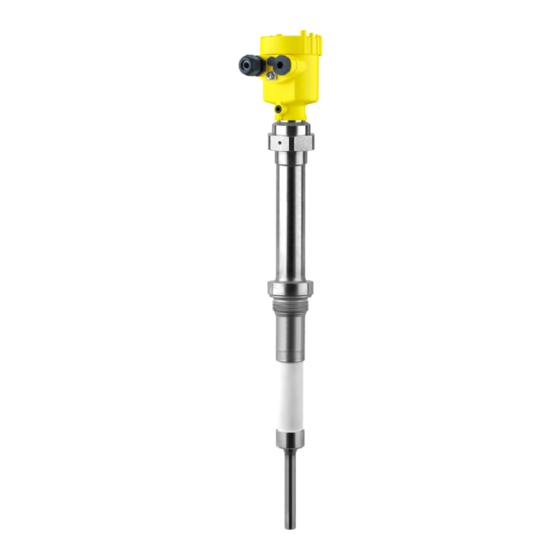
Supplementary instructions manual "Plug connector for level sensors" (optional) Ex-specific "Safety instructions" (with Ex versions) if necessary, further certificates The VEGACAP 67 consist of the following components: Constituents Housing cover Housing with electronics Process fitting with electrode... - Page 8 3 Product description Fig. 1: VEGACAP 67 - with plastic housing Housing cover Housing with electronics Process fitting Supporting tube Ceramic insulator Type label The type label contains the most important data for identification and use of the instrument: Article number...
-
Page 9: Principle Of Operation
3 Product description 3.2 Principle of operation VEGACAP 67 is a point level sensor with capacitive probe for level Application area detection under high process temperatures. VEGACAP 67 is very rugged and maintenance-free and can be used in all areas of industrial process technology. -
Page 10: Operation
The capacitance change is converted by the electronics module into a switching command. VEGACAP 67 is a compact instrument, i.e. it can be operated without Voltage supply external evaluation system. The integrated electronics evaluates the level signal and outputs a switching signal. - Page 11 Not exposed to corrosive media Protected against solar radiation Avoiding mechanical shock and vibration Storage and transport Storage and transport temperature see chapter "Supplement - temperature Technical data - Ambient conditions" Relative humidity 20 … 85 % VEGACAP 67 • - contactless electronic switch...
-
Page 12: Mounting
You can find the specifications in chapter "Technical data" or on the type label. In general, VEGACAP 67 must be mounted vertically. The instrument Switching point must be mounted in such a way that the probe is at the height of the requested switching point. -
Page 13: Mounting Instructions
For this reason, do not use an overly tion long probe for VEGACAP 67, but check if you can mount a short level switch on the side of the vessel in horizontal position. Inflowing medium If the instrument is mounted in the filling stream, unwanted false... - Page 14 The probe must be mounted in a way that takes the arrangement of the filling and emptying apertures into account. To compensate measurement errors caused by the material cone in cylindrical vessels, the sensor must be mounted at a distance of d/6 from the vessel wall. VEGACAP 67 • - contactless electronic switch...
- Page 15 4 Mounting Fig. 5: Filling and emptying centred VEGACAP 67 • - contactless electronic switch...
- Page 16 Make sure that the max. permissible tensile load of the suspension cable is not exceeded. The danger of this happening exists particularly with very heavy solids and large meas. lengths. The max. permissible load is stated in chapter "Technical data". VEGACAP 67 • - contactless electronic switch...
-
Page 17: Connecting To Power Supply
Take note of the general installation regulations. As a rule, connect VEGACAP 67 to vessel ground (PA), or in case of plastic vessels, to the next ground potential. -
Page 18: Wiring Plan, Single Chamber Housing
Fig. 7: Connection steps 5 and 6 5.3 Wiring plan, single chamber housing Housing overview Fig. 8: Material versions, single chamber housing Plastic (not with dust-Ex) Aluminium Stainless steel Filter element for air pressure compensation VEGACAP 67 • - contactless electronic switch... - Page 19 When VEGACAP 67 is used as part of an overfill protection system according to WHG, also note the regulations of the general type approval.
- Page 20 5 Connecting to power supply Fig. 10: Wiring plan Voltage supply VEGACAP 67 • - contactless electronic switch...
-
Page 21: Set Up
Note: As a rule, always set the mode with the mode switch (3) before starting setup VEGACAP 67. The switching output will change if you set the mode switch (3) afterwards. This could possibly trigger other connected instruments or devices. - Page 22 When the control lamp (6) lights green: continue with the next item. Turn the potentiometer (1) very slowly anticlockwise until the control lamp (6) lights red. The measuring system is now ready for operation. VEGACAP 67 • - contactless electronic switch...
-
Page 23: Functional Chart
Switch open Mode min. Dry run protection Switch closed Green Mode min. Dry run protection Switch open Failure of the sup- ply voltage (min./max. mode) Switch open Failure Switch open flashes red VEGACAP 67 • - contactless electronic switch... -
Page 24: Maintenance And Fault Rectification
7 Maintenance and fault rectification 7 Maintenance and fault rectification 7.1 Maintenance When used as directed in normal operation, VEGACAP 67 is completely maintenance free. 7.2 Rectify malfunctions Reaction when malfunc- The operator of the system is responsible for taking suitable measures tions occur to remove interferences. - Page 25 à Mount the instrument at a location in the vessel where e.g. no mounds can form. Signal lamp flashes red Electronics module has detected a failure à Exchange the instrument or send it in for repair VEGACAP 67 • - contactless electronic switch...
-
Page 26: Exchange Of The Electronics Module
Make sure that the housing is not rotated during the electronics exchange. Otherwise the plug may be in a different position later. Insert the electronics module carefully. Make sure that the plug is in the correct position. VEGACAP 67 • - contactless electronic switch... -
Page 27: Shortening Of The Probe
The electronics exchange is now finished. 7.4 Shortening of the probe The rod of the probe can be shortened to any length. Shorten the rod probe to the requested length with a metal saw. VEGACAP 67 • - contactless electronic switch... -
Page 28: Instrument Repair
If a repair is necessary, please proceed as follows: You can download a return form (23 KB) from our Internet homepage www.vega.com under: "Downloads - Forms and certificates - Repair form". By doing this you help us carry out the repair quickly and without having to call back for needed information. -
Page 29: Dismounting
Correct disposal avoids negative effects to persons and environment and ensures recycling of useful raw materials. Materials: see chapter "Technical data" If you have no possibility to dispose of the old instrument professionally, please contact us concerning return and disposal. VEGACAP 67 • - contactless electronic switch... -
Page 30: Supplement
Rod (ø 15 mm/0.591 in) 0.275 … 6 m (0.902 … 19.69 ft) Cable (ø 8 mm/0.315 in) 0.5 … 40 m (1.64 … 131.23 ft) Cable connected electrically conductive with the gravity weight. VEGACAP 67 • - contactless electronic switch... - Page 31 (32 °F) (572 °F) (752 °F) Fig. 32: Process temperature - Process pressure Process temperature Process pressure Temperature range with external housing ≥ 1.5 Dielectric figure Electromechanical data Cable entry/plug (dependent on the version) VEGACAP 67 • - contactless electronic switch...
- Page 32 400 mA (at I > 300 mA the ambient temperature can Max. be max. 60 °C/140 °F) max. 4 A up to 40 ms Electrical protective measures IP 66/IP 67 Protection rating Overvoltage category Protection class VEGACAP 67 • - contactless electronic switch...
-
Page 33: Dimensions
") ") M20x1,5/ M20x1,5/ M20x1,5/ M20x1,5 M20x1,5/ ½ NPT ½ NPT ½ NPT ½ NPT Fig. 33: Housing versions Plastic housing Stainless steel housing, electropolished Stainless steel housing - precision casting Aluminium housing VEGACAP 67 • - contactless electronic switch... - Page 34 ") ") Fig. 34: VEGACAP 67 - threaded version G1½ A (ISO 228 T1) and 1½ NPT, -50 … +300 °C (-58 … +572 °F) Version -50 … +400 °C (-58 … +752 °F) only with external housing. See supplementary instructions manual "External housing - VEGACAP, VEGACAL"...
-
Page 35: Information
Les lignes de produits VEGA sont globalement protégées par des droits de propriété intellectuelle. Pour plus d'informations, on pourra se référer au site http://www.vega. VEGA lineas de productos están protegidas por los derechos en el campo de la propiedad industrial. Para mayor información revise la pagina web http://www.vega.com Линии... -
Page 36: Information
All statements concerning scope of delivery, application, practical use and operating conditions of the sensors and processing systems correspond to the information avail- able at the time of printing. © VEGA Grieshaber KG, Schiltach/Germany 2010 31314-EN-100407 Subject to change without prior notice...
Need help?
Do you have a question about the VEGACAP 67 and is the answer not in the manual?
Questions and answers