Table of Contents
Advertisement
Advertisement
Table of Contents
Troubleshooting

Related Manuals for Victron energy Cerbo GX


Summary of Contents for Victron energy Cerbo GX
- Page 1 ENGLISH Cerbo GX Manual...
-
Page 2: Table Of Contents
Cerbo GX Manual Table of Contents 1. Introduction ..........................4 1.1. What is the Cerbo GX? ..................... 4 1.2. What's in the box? ......................4 2. Installation ..........................5 2.1. Overview of connections ....................5 2.2. Power ......................... 5 2.3. Connecting Victron products ....................6 2.3.1. - Page 3 14.11. Q11: How long should an automatic update take? ..............63 14.12. Q12: I have a VGR with IO Extender, how can I replace this with a Cerbo GX? ........ 63 14.13. Q13: Can I use Remote VEConfigure, as I was doing with the VGR2? .......... 63 14.14.
-
Page 4: Introduction
There is an optional touch screen accessory for the Cerbo GX called the Touch. Monitoring of the system can be done either with the Cerbo GX in front of you - or from anywhere in the world using an internet connection and the Portal. -
Page 5: Installation
On the Cerbo GX, the USB socket closest to the HDMI connector can only be used to power a GX Touch. That USB port can not be used for any data related functions such as VE.Direct to USB cables, USB-sticks, USB-GPS-es, or other common USB usa- ges. -
Page 6: Connecting Victron Products
To connect multiple VE.Bus products, configured as a parallel, split-phase or three phase VE.Bus system, connect either the first or the last VE.Bus product in the chain to either one of the VE.Bus sockets on the back of the Cerbo GX. Use a standard RJ45 UTP cable, see our pricelist. -
Page 7: Battery Monitor Bmv-700 Series; And Mppts With A Ve.direct Port
Notes about older VE.Direct MPPTs • An MPPT 70/15 needs to be from year/week 1308 or later. Earlier 70/15s are not compatible with the Cerbo GX , and unfortu- nately upgrading the MPPT firmware will not help. To find the year/week number of your model, look for the serial number which is printed on a label on its back. -
Page 8: Ve.can Resistive Tank Sender Adapter
It can communicate at both 4800 and 38400 baud rates. Plug the unit into either of the two USB sockets …connec- tion may take a few minutes, but the Cerbo GX will automatically recognize the GPS. The unit's location will automatically be sent to the VRM online portal and its position shown on the map. -
Page 9: Connecting Imt Solar Irradiance, Temperature And Wind Speed Sensors
Cerbo GX Manual • Navico Fluid Level Sensor Fuel-0 PK, partno. 000-11518-001. Note that you need a Navico display to configure the Capacity, Fluid type, and other parameters of the sensor. See voltage warning below. • Oceanic Systems (UK) Ltd (OSUKL) - 3271 Volumetric Tank Sender. In case it doesn’t work, it needs a firmware update. Con- tact OSUKL for that. - Page 10 Cerbo GX Manual Wire connections Si-Sensor Victron RS485 to USB interface Signal Brown Orange RS485 Data A + Orange Yellow RS485 Data B - Power Pos - 12 to 28 VDC Black Power Neg/Gnd - 0 VDC Black (thick) Ground / Cable Shield / PE...
- Page 11 Cerbo GX Manual • All wiring is properly terminated (including unused wires) and properly isolated from weather/water ingress • The sensor housing is not opened or tampered with during installation - as sealing integrity will be compromised (and warranty void) The IMT Si-RS485TC series solar irradiance sensor includes internal Galvanic Isolation (up to 1000V) between power supply and RS485 Modbus circuits, accordingly the non-isolated Victron RS485 to USB interface is suitable for most installations.
- Page 12 Cerbo GX Manual Within the ‘Settings’ sub-menu it is possible to manually enable and disable any optional/additional external sensors that are con- nected to the IMT Si-RS485 Series irradiance sensor.
-
Page 13: Data Visualisation - Vrm
Cerbo GX Manual 2.8.1. Data Visualisation - VRM To review logged historical data on the VRM portal, expand the ‘Meteorological Sensor’ widget list and select the ‘Meteorological Sensor’ widget. Data from all available sensor types will be automatically displayed in the graph. Individual sensors/parameters can also be disa-... - Page 14 Cerbo GX Manual...
-
Page 15: Internet Connectivity
This video explains how to connect LAN, WiFi and a GX GSM: https://www.youtube.com/embed/645QrB7bmvY 3.1. Ethernet LAN port When you connect an ethernet cable between a router and Cerbo GX, the Settings -> Ethernet page of your Cerbo GX will con- firm connection. 3.2. Wi-Fi The Cerbo GX includes built in Wi-Fi. -
Page 16: Gx Gsm
3.4. Mobile (cellular) network using a 3G or 4G router To connect the Cerbo GX to a mobile (cellular) network, such as a 3G or 4G network, use a cellular router. Connect the Cerbo GX to that router with either a LAN cable or the router's Wi-Fi network. -
Page 17: Ip Configuration
3.7. Connecting both Ethernet and Wi-Fi (failover) It is possible to connect the Cerbo GX to both Ethernet and Wi-Fi. In this case, the Cerbo GX will try to determine which interface provides an active internet connection and then use that interface. When both have an active internet connection, the Ethernet connection is used. -
Page 18: More Information About Setting Up An Internet Connection And Vrm
Cerbo GX Manual 3.9. More information about setting up an internet connection and VRM • Setting up a VRM account • VRM Portal alarms and monitoring • VRM Portal - Frequently asked questions... -
Page 19: Accessing The Gx Device
Cerbo GX Manual 4. Accessing the GX device It is possible to access the GX device using either a smartphone, tablet or computer. This access is called Remote Console. In GX devices with a display this Remote Console feature may be disabled by default and need to be enabled. - Page 20 Make sure that the Cerbo GX is powered on, and the Bluetooth LED is blinking. Open the VictronConnect App within 10 meters of the Cerbo GX and wait for nearby devices to be discovered. Once discovered, Click or Tap on the Cerbo GX.
- Page 21 Cerbo GX Manual From the main device screen it is possible to change the networking settings, view the system on VRM, or open the Remote Con- sole. Network settings for the Cerbo GX are set in the Cog menu.
-
Page 22: Accessing Via The Built-In Wifi Access Point
2. Go to the WiFi settings on your phone / tablet / laptop. 3. After searching, the Cerbo GX will show up in the list, as Venus-HQ1940DEFR4-3b6. Where HQ… is the serial number as printed on the side of the box. -
Page 23: Accessing Remote Console Via The Local Lan/Wifi Network
IP Address on VRM On the VRM Portal, you'll find the IP address on the Device List page of the installation. Note that this does require the Cerbo GX to be connected to the internet. - Page 24 Cerbo GX Manual Network (on Microsoft Windows) In a local network, for example at home, you can also find the Cerbo GX in the Windows 'Network' overview: Double-clicking the icon will open up Remote Console on LAN. Open the 'Properties' window to see the IP address.
-
Page 25: Accessing Via Vrm
Step by step instructions: First, connect the Cerbo GX to the internet by plugging it into a working Ethernet network which has a DHCP server, as most networks do, and which is connected to the internet. The Cerbo GX will immediately connect to VRM. - Page 26 Cerbo GX Manual...
-
Page 27: Configuration
Reboot? Reboots the GX device Audible alarm When there is an alarm on the Cerbo GX or a connected product, the Cerbo GX will beep - unless this setting is set to 'Off'. Demo mode Disabled Demonstrates product and installation features to a client or at an exhibition. This simulation mode will allow better understanding without (yet) changing any settings. - Page 28 Cerbo GX Manual Item Default Description SVS - Shared voltage sense No / Yes - The GX device automatically selects the best available voltage measurement and shares it with other connected devices. STS - Shared temperature No / Yes - The GX device will send the measured battery temperature to the Inverter/charger sys- sense tem as well as all connected Solar Chargers.
- Page 29 Cerbo GX Manual Item Default Description Find PV inverters Scan for available PV inverters Detected IP addresses Shows the IP address of PV inverters that have been discovered Add IP address manually If an inverter has a manually assigned IP address, you can add it directly here.
- Page 30 Select the relay function. Possible functions are 'Alarm relay', 'Generator start/stop', 'Tank pump' and 'None' (disabled). Polarity Normally open Select the polarity of the relay on the back of the Cerbo GX. 'Normally open' or 'Normally closed'. (Note that setting it to normally closed increases the Cerbo GX power draw.) Services ModbusTCP This setting enables the ModbusTCP service.
-
Page 31: Battery State Of Charge (Soc)
1. Enable and configure the Battery Monitor in VEConfigure. 2. In the Cerbo GX , in Settings → System setup, verify the selected Battery Monitor. It should be set to the Multi or Quattro. (B) Battery with Multi or Quattro and MPPT Solar Chargers -ALSO- An EasySolar with GX Device built-in No battery monitor is required, as long as all MPPT Solar Chargers are Victron products and are connected to the Cerbo GX . -
Page 32: Notes On Soc
Cerbo GX Manual Note that this feature requires recent firmware versions in both the Multis or Quattros (402 minimum), and the Cerbo GX (v2.06 minimum). (C) Batteries with a built-in battery monitor In cases where the system includes a battery which has a built-in battery monitor and SOC calculation - such as many of the... - Page 33 Cerbo GX Manual In the image above we have chosen the Automatic setting. When automatic is selected the System setup screen will be as shown in the image below. The 'Automatic' function uses the following logic: 1. When available, it will use a dedicated Battery Monitor, such as the BMV or a Lynx Shunt, or a battery with built-in battery monitor.
-
Page 34: Details On Ve.bus Soc
Cerbo GX Manual 3. the system has other DC loads, or other chargers, connected to the same battery, which are not connected to the Cerbo GX. A short explanation: the VE.Bus SOC as determined by the Multi or Quattro will be incorrect in above situation. As it will not take the discharge and charge currents by those other DC Loads, and also unmonitored chargers, into account. -
Page 35: Updating Gx Firmware
Cerbo GX Manual 6. Updating GX Firmware 6.1. Via internet or with microSD-card/USB-stick There are two ways to update the firmware: 1. Update it via the internet, either manually or let it check for new updates every day 2. Update it from a microSD-card or USB-stick 6.2. -
Page 36: Changelog
Cerbo GX Manual Step 4. Initiate the update Navigate to Settings → Firmware → Offline updates. Press Check for updates If the firmware in the microSD-card or USB-stick is newer than the running one, “Update available” item will appear, press it to start the update process. -
Page 37: Ve.bus Inverter/Charger Monitoring
This chapter explains the implications of enabling or disabling user control of the input current-limiter setting, as seen here in the menu: The limit as set by the user in the Cerbo GX will be applied to all inputs where 'Overruled by remote', configured with VictronCon- nect or VEConfigure, is enabled: Using the example of a boat with two AC inputs and a Quattro where: 1. -
Page 38: Phase Rotation Warning
Cerbo GX Manual Minimum input current limit values When PowerAssist is enabled in VEConfigure, there is a minimum input current limit. The actual limit differs for each model. After setting the input current to a value below the limit, it will automatically be increased again to the limit. -
Page 39: Grid Failure Monitoring
Cerbo GX Manual And also it will be listed in the Alarm Log on VRM, and an email will be sent; using the VRM Alarm Monitoring system. 7.3. Grid failure monitoring When this feature is enabled, an alarm is raised when the system hasn't been connected to the AC input configured to be Grid or Shore for more than 5 seconds. - Page 40 Cerbo GX Manual Redetects the type of inverter/charger and its features & configuration. Use this feature when, for example, a VE.Bus BMS used to be part of a system, and is no longer. System reset Restarts the inverter/charger when it has stopped retrying. For example after a (very) heavy overload; or three overloads in a row.
-
Page 41: Dvcc - Distributed Voltage And Current Control
Cerbo GX Manual 8. DVCC - Distributed Voltage and Current Control 8.1. Introduction and features Enabling DVCC changes a GX device from a passive monitor into an active controller. The available features and effects of ena- bling DVCC depend on the type of battery used. The effect also depends on the installed Victron components and their configura- tion. -
Page 42: Dvcc Requirements
DVCC. For Gel, AGM, OPzS and other lead batteries, DVCC can be used without any problem. The same is true for Victron Energy lithi- um batteries with the VE.Bus BMS, the Lynx Ion + Shunt BMS or the Lynx Ion BMS. DVCC is the preferred operating mode for Redflow ZBM2/ZCell batteries using the Redflow CANBus BMS. -
Page 43: Dvcc Features For All Systems
Cerbo GX Manual The MPPTs internal charge algorithm is disabled; instead it's being controlled by a charge voltage setpoint coming from the inver- ter/charger. MPPT indicated charge state: Ext. control. Battery The internal charge algorithm is disabled; and instead, the device is being controlled by the battery. -
Page 44: Shared Temperature Sense (Sts)
• BMV-712 battery monitor • Lynx Shunt VE.Can battery monitors • Temperature inputs on a Cerbo GX (and same for other GX devices that have a temperature input) • Multi/Quattro inverter/charger • Solar Chargers (if fitted with a temperature sensor) 8.4.4. -
Page 45: Dvcc For Systems With The Ess Assistant
Cerbo GX Manual 8.6. DVCC for systems with the ESS Assistant • The ESS Keep batteries charged mode works properly. It does not without DVCC. • A fixed solar offset of 0.4V is used instead of a variable 2V. (values for 48V systems, divide by 4 for 12V). Note that this solar offset is only applied when ESS-mode is set to Optimized in combination with the Feed-in excess solar charger power-setting enabled, or when ESS-mode is set to Keep batteries charged. -
Page 46: Vrm Portal
• SDXC type microSD cards which have greater than 32 GB capacity are often formatted with exFAT, and therefore cannot be used with the Cerbo GX without reformatting and possibly re-partitioning. Manually transferring datalogs to VRM... -
Page 47: Trouble Shooting Data Logging
80 and 443. Note that should never be an issue, unless on very specialized company networks. Note that the Cerbo GX does not support a proxy setup. For more details on the required networking, see here. Step 1: Update the GX Device to the latest available firmware... - Page 48 When using Ethernet and State shows 'Unplugged', verify that the Ethernet network cable is not faulty: try another one. The two lights at the back of the Cerbo GX, where the Ethernet RJ45 cable plugs in, should be lit or blinking. Two dead lights indicate a connection problem.
- Page 49 Cerbo GX Manual If a Connection error is shown, the Cerbo GX is not able to contact the VRM database. The connection error will show an error code that indicates the nature of the connectivity problem. Also, details of the error message are shown, to facilitate on site IT experts to diagnose the problem.
-
Page 50: Analysing Data Offline, Without Vrm
5. After the restart, check the Remote Console on VRM status shows online or a port number. In case it says offline, or port number 0, the Cerbo GX was unable to connect to the Remote Console server. This is normally caused by a (company) fire- wall, blocking the connection. - Page 51 Cerbo GX Manual When using Remote Console on VRM, the browser will connect to either vncrelay.victronenergy.com, or vncrelay2.victronener- gy.com, using websockets on port 443. For more details of used connections by the GX Device, see Q15 of the FAQ.
-
Page 52: Marine Mfd Integration By App
Cerbo GX Manual 10. Marine MFD integration by App 10.1. Introduction & requirements A Glass Bridge is a MFD (Multi-Functional Display) that integrates a boat’s systems and navigation status into a large screen or screens at the helm of the vessel, so doing away with multiple gauges, brackets and wiring complications. -
Page 53: Compatible Mfds And Instructions
Cerbo GX Manual • Battery system. • Victron GX Device (all models are compatible: CCGX, Cerbo GX, Venus GX, and so forth) • Victron Inverter/charger. • Victron Battery monitor. • Ethernet network cable connected between MFD and the GX device •... -
Page 54: Marine Mfd Integration By Nmea2000
Cerbo GX Manual 11. Marine MFD integration by NMEA2000 11.1. NMEA2000 Introduction Our GX Devices feature an NMEA 2000-out function: when enabled, the GX Device acts as a bridge: it makes all Battery moni- tors, Inverter/chargers and other products connected to the GX device available on the NMEA2000 network. -
Page 55: Nmea2000 Related Menu Settings
Cerbo GX Manual Displays not being capable of doing so will regard the data as belonging to the mains (utility). The Inverter Output is then interpreted as utility #0 and Inverter Input as utility #1. These default instance numbers can be changed by a network configuration tool if necessary. -
Page 56: Nmea2000-Out Technical Details
Cerbo GX Manual Setting Default Description Check unique Searches for other devices that use the same unique number. When the search is completed it will respond with either an OK, or numbers the text : There is another device connected with this unique number, please select another one. -
Page 57: Nmea2000 Changing Instances
Cerbo GX Manual How to configure the instances depends on the equipment and software that is used to read them from the CAN-bus. Examples of equipment and software meant here are MFDs such as from Garmin, Raymarine or Navico; as well as more software oriented solutions from for example Actisense and Maretron. -
Page 58: Pgn 60928 Name Unique Identity Numbers
Cerbo GX Manual To change the Device instances, see this document. WARNING: these (Victron-)features depend on the Device Instance: 1. For an ESS system with Solar chargers connected on a VE.Can network, those Solar chargers must remain to be configured to their default Device instance (0) for proper operation. -
Page 59: Digital Inputs
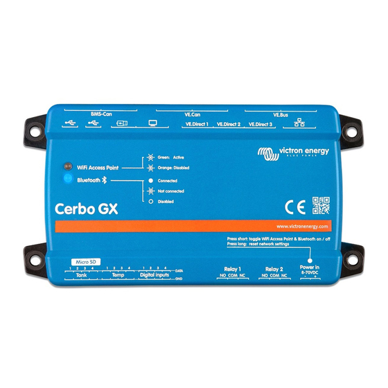
Cerbo GX Manual 12. Digital Inputs The Cerbo GX digital inputs are shown in the overview of connections. [5] 12.1. Configuration Each of the digital inputs can be configured as one of a number of predefined sensors that can also be configured as alarms. -
Page 60: Read-Out Of Digital Inputs Via Modbus-Tcp
Cerbo GX Manual Other parameters related to that function can be configured by entering the device menu and selecting Setup. For sensors and alarms, you can decide whether the input should be treated as an alarm condition, whether the labels should be inverted, and whether the logical levels should be inverted. -
Page 61: Error Codes
Cerbo GX Manual 13. Error Codes Different origins of errors On your GX device, some error codes shown will be from the GX device itself, in that case see below list. As the system control panel, it also shows error codes from the connected devices. -
Page 62: Faq
4. For parallel/three phase systems consisting of more than 5 units: depending on temperature and other circumstances, it might not be possible to switch a system back on after switching it off with the Cerbo GX. As a work around you'll need to unplug the VE.Bus cable from the back of the Cerbo GX. -
Page 63: Q7: There Is A Menu Entry Named "Multi" Instead Of The Ve.bus Product Name
Cerbo GX, the Cerbo GX cannot obtain the detailed product name and shows “Multi” instead. To get the proper name again, go into the Multi menu on the Cerbo GX and set the Switch menu entry to On or in case a Digital Multi Control is present, set the physical switch to On. -
Page 64: Q14: The Blue Power Panel Could Be Powered Through The Ve.net Network, Can I Also Do That With A Cerbo Gx
14.15. Q15: What type of networking is used by the Cerbo GX (TCP and UDP ports)? Basics: • The Cerbo GX needs to get a valid IP address from a DHCP server, including a working DNS server and gateway, or a static IP configuration. • DNS port 53 UDP and TCP •... -
Page 65: Q18: What Is The Data Usage Of The Cerbo Gx
Data usage depends heavily on amount of connected products, and behavior and usage of those products. The measurements below are an indication only, and taken from a system with one Cerbo GX, one Multi, one BMV and one MPPT. Log interval set to 15 minutes. -
Page 66: Q21: I Love Linux, Programming, Victron And The Cerbo Gx. Can I Do More
Please check the remote switch connection on the Multi control PCB. There should be a wire bridge between the left and middle terminal. The Cerbo GX switches a line which enables the power of the Multi control board. After 10 seconds this line is released and the Multi should take over from there. -
Page 67: Gpl Note
Cerbo GX Manual Firmware versions until v2.30 did not report the error. Since v2.30; its visible on the device itself (in the GUI) and on the VRM Portal. 14.25. GPL Note The software included in this product contains copyrighted software that is licensed under the GPL. You may obtain the Corre-... -
Page 68: More Information
Cerbo GX Manual 15. More information • GX - Generator auto start/stop • GX - Using Fischer Panda Generators • GX - GSM cellular modem • VRM Portal - Remote VEConfigure and remote firmware updates • VRM Portal - Documentation and troubleshooting...
Need help?
Do you have a question about the Cerbo GX and is the answer not in the manual?
Questions and answers