Table of Contents
Advertisement
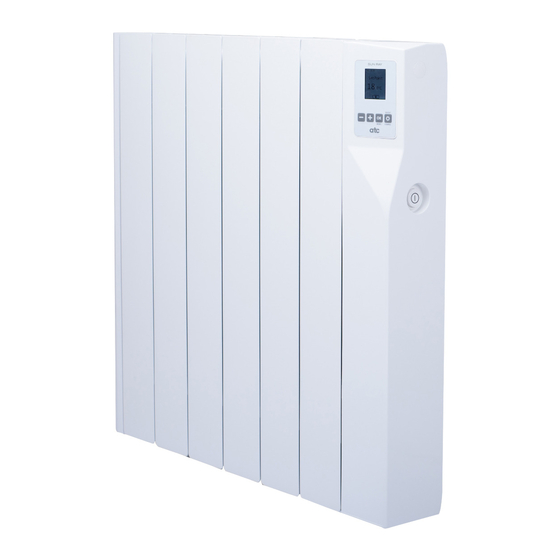
Sun Ray RF
Operating and Installation Instructions
(Read these instructions carefully and retain for future reference)
A qualified electrician must carry out the electrical installation of this radiator. The Electrical
installation must comply with the current UK and Irish regulations. Any claim on the warranty
could be invalid if these requirements have not been met.
Electric Radiator
Models:
Sun Ray RF 350w
Sun Ray RF 500w
Sun Ray RF 750w
Sun Ray RF 1000w
Sun Ray RF 1250w
Sun Ray RF 1500w
Sun Ray RF 1800w
NOTE:
1
Advertisement
Table of Contents

Related Manuals for ATC Sun Ray RF Series


Summary of Contents for ATC Sun Ray RF Series
- Page 1 Sun Ray RF Electric Radiator Operating and Installation Instructions (Read these instructions carefully and retain for future reference) Models: Sun Ray RF 350w Sun Ray RF 500w Sun Ray RF 750w Sun Ray RF 1000w Sun Ray RF 1250w Sun Ray RF 1500w Sun Ray RF 1800w NOTE: A qualified electrician must carry out the electrical installation of this radiator.
-
Page 2: Table Of Contents
CONTENT IMPORTANT INFORMATION ......TECHNICAL DATA....... . . GENERAL INFORMATION . -
Page 3: Important Information
• This heating apparatus holds a specific amount of special oil. Repairs where it is necessary to open the oil tank must only be made by the manufacturer or ATC. ATC should be contacted in case of any oil leakage. -
Page 4: Technical Data
TECHNICAL DATA Number Of Power Size (mm) Net Weight MODEL Fuse Rating Fins Rating (W) HxWxD (Kg.) Sun Ray RF 350 580 x 340 x 100 5 Amp. Sun Ray RF 500 580 x 420 x 100 5 Amp. Sun Ray RF 750 580 x 580 x 100 5 Amp. -
Page 5: Installation Instructions
INSTALLATION INSTRUCTIONS ELECTRICAL CONNECTION A qualified electrician must carry out the electrical installation of this radiator. The electrical installation must comply with the current UK and Irish regulations. Any claim on the warranty could be invalid if these requirements have not been met. The radiator requires a 230/240V 50/60Hz power supply. -
Page 6: Mounting The Radiator
MOUNTING THE RADIATOR Place the radiator on the floor, as shown in Figure 1. For radiators with 4, 6, 8 or 10 elements position the supports supplied with the radiator as shown in Figure 1. For radiators with 12 elements the supports should be positioned between the second and third elements from each end. -
Page 7: Control Options
Once the heater is hanging as shown in figure 3b, attach locking bracket shown in figure 4 to the bottom right hand side of the heater using screw 1. Mark the location of screw 2 on the wall and then remove the bracket. Drill the hole for the fixing and insert the supplied wall plug, re-attach the locking bracket to the heater and then fix the heater to the wall with screw 2, then push on the left side of the locking plates on the top brackets until a click is heard. -
Page 8: Operating Instructions
Switching ON (Master): OPERATING INSTRUCTIONS Once the radiator has been mounted on the wall The control is based on four buttons and a TFT display. and correctly connected to the main electricity power supply, press the main On-Off switch on the right hand side of the radiator. -
Page 9: Manual Programming
MANUAL PROGRAMMING SET PROGRAM TEMPERATURES To assist with programming the TFT screen is Adjusting the temperature set points in the backlit and will stay illuminated for approximately following way will only affect the temperatures that 10 seconds after the last button is pressed. (to are used for program modes. -
Page 10: Entering A Program
Select the TIME menu with the +/- keys and To enter a program into the PROGRAM press OK. radiator first select the day of the Tuesday COPY The current set time is shown on the display, to week in the upper left corner of mode change the Hours or Minutes move the underline the week and press OK, change... -
Page 11: Boost
To Adjust the brightness of the To make sure your program is running Press the DISPLAY SETTINGS screen, select Brightness level OK/MODE button until AUTO is shown at the Brightness Level and press OK, the ON levels are bottom of the screen. between 1=25%, 2=50%, 3=75% Level Tue. -
Page 12: Programming With App
PROGRAMMING WITH APP When the keypad is locked the radiator will still receive communications from the Sun Ray RF To programme your Sun Ray RF with a Sun Gateway. Ray RF Gateway you must pair the radiator to the Gateway. First you must activate the pairing/ discovery mode in the Gateway, press Link button for 2 seconds. - Page 13 The Open window setting will EASY Mode is a simple mode Open Window EASY mode turn the heating of the radiator off of operation where by only the if the unit detects a rapid drop in + and – buttons on the radiator temperature over a short period operate to increase or decrease of time.
-
Page 14: Password
PASSWORD RUNBACK MODE The Password Function of the Sunray RF The Sunray RF Heater comes with a runback Radiator serves a number of functions; Keylock, mode for use when the heater will be installed in Advanced menu access and also Runback access areas where restricted user control is required. - Page 15 MAX TEMPERATURE Runback The Default time for Runback The Max Temperature mode Runback Settings to operate is 30 minutes, this can allows the installer to set a Max Time Runback be increased in ½ hour sections temperature higher than the RunBack Temp Setback up to 8 hours (480 mins) by using...
-
Page 16: Error Codes
Max Temp. Set point an Error code on the screen. Runback Set point In the case of an error code please contact Technical@ATC.ie for support Setback Limit Heating Start Temperature Time When all 3 settings are activated then the user has a choice between Setback as a minimum and the Max temp setting as a maximum. -
Page 17: Troubleshooting
TROUBLESHOOTING If the power of the Lithium battery drops, the screen shows the low battery icon in startup screen for 5 sec. and returns to LOW BATTERY normal mode. In every active screen a small Wed. 11:00 icon will remind the user that the battery is flat. -
Page 18: Default Values
DEFAULT VALUES Default mode: OFF Type of control: PID Temperature offset: 0ºC Open window detection: disabled Autoadaptive: disabled Programming in one hour intervals, all hours in antifrost mode Setpoint temperatures: Anti-freeze 7ºC Eco 18ºC Comfort 21ºC Manual temperature: 21ºC Boost mode temperature: 21ºC Boost mode time: 1h Low Surface Temperature: disabled Password status: activated... -
Page 19: Ecodesign Table
With adaptive start control With distance control option ATC Electrical and Mechanical Head Office & Showrooms ATC House, Broomhill Drive, Tallaght, D24 EF99, Ireland. IRL Tel: +353 (0)1 4625111 UK Tel: +44 (0)203 5649164 Fax: +353 (1) 452 0887 Email: sales@atc.ie... -
Page 20: Maintenance And Care
Radiators clean may result in dust becoming burnt and depositing on the wall above the heater in the form of dark streaks or patches. This type of marking is expressly due to failure to keep the heater and surrounding area clean. ATC...
Need help?
Do you have a question about the Sun Ray RF Series and is the answer not in the manual?
Questions and answers