Table of Contents
Advertisement
Advertisement
Table of Contents

Related Manuals for Topcon CL-200


Summary of Contents for Topcon CL-200
- Page 1 INSTRUCTION MANUAL COMPUTERIZED LENSMETER CL-200...
-
Page 2: Introduction
• High accuracy measurements with ease of operation • Easy to use color LCD This Instruction Manual covers an overview of the TOPCON Computerized Lensmeter CL- 200, basic operations, troubleshooting, maintenance and cleaning. To ensure the efficient, safe use, read through “Safety Indications” and “Safety Precau- tions”... - Page 3 WORKING ENVIRONMENT Indoor use Altitude up to 2,000m Pollution degree II Temperature range: 5-40°C Maximum relative humidity 80% for temperatures up to 31°C decreasing linearly to 50% rela- tive humidity at 40°C STORAGE METHOD (without package) 1. ENVIRONMENTAL CONDITIONS Indoor use Altitude up to 2,000m Pollution degree II Temperature range: 5~40°C Maximum relative humidity 80% for temperatures up to 31°C decreasing linearly 50% relative humidity at 40°C...
-
Page 4: Displays For Safe Use
DISPLAYS FOR SAFE USE In order to encourage the safe use of this product, warnings labels are placed on the product and written in the instruction manual. We suggest that everyone understands the meaning of the following displays and icons before reading the “Safety Cautions”... -
Page 5: Safety Precautions
SAFETY PRECAUTIONS WARNING Icons Prevention item Page To avoid fire/electric shocks, connect the power plug to a 3P AC outlet (with ground) and secure grounding. To prevent electrical shock, turn off the power switch and discon- nect power cable before replacing fuses. Replace fuses with the same rating and type. -
Page 6: Usage And Maintenance
• TOPCON shall not take any responsibility for damage derived from the inability to use this equipment, such as a loss of business profit and suspension of business. -
Page 7: Warning Indications And Positions
WARNING INDICATIONS AND POSITIONS To insure safety, warning labels are provided. Use the equipment correctly by following the warning instructions. If any of the following labels are missing, please contact us at the address stated on the back cover. WARNING •... -
Page 8: Table Of Contents
CONTENT INTRODUCTION ......................1 DISPLAYS FOR SAFE USE ..................3 SAFETY PRECAUTIONS ...................4 USAGE AND MAINTENANCE..................5 USER MAINTENANCE....................5 ESCAPE CLAUSE ......................5 WARNING INDICATIONS AND POSITIONS .............6 COMPONENTS COMPONENT NAMES....................8 ACCESSORIES ......................9 MONITOR MONITOR SCREEN ....................10 MENU SCREEN .......................12 MENU LIST.......................13 PREPARATION INSTALLATION ......................15 SETTING THE PAPER .....................15 USING THE INSTRUMENT MEASURING ......................17... -
Page 9: Components
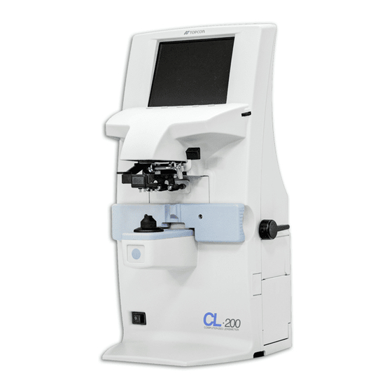
COMPONENTS COMPONENT NAMES BRIGHT control dial Axis marker lever Lens retainer Lens table Lens support RS-232C MEMORY button Power switch (1) Mode buttons Pressed to change the mode, and when pressed; MENU PROG EXIT Returns to the initial state. Pressed on to connect the spectral transmittance meter (optional). -
Page 10: Accessories
ACCESSORIES The following are standard accessories. Make sure that all these items are included (quantity). Power cable (1) Lens protection pad (1) Fuse (2) Silicon cloth (1) Contact lens support (1) Dust cover (1) Printer paper (2) Instruction manual (1) (with printer specification) Printer paper shaft (1) Supply ink (1) -
Page 11: Monitor Monitor Screen
And it varies depending on the symbol used in the spherical equivalent power. Be noted that the target motion is different from that of Topcon telescopic lensmeters. For axis marking procedures, refer the instruction in Page 27. - Page 12 ENLARGEMENT: When is selected, the SCA display is horizontally MENU/DISPLAY/HORIZONTAL LARGE enlarged to make it easier to see. When is selected, the SCA display is vertically MENU/DISPLAY/VERTICAL LARGE enlarged to make it easier to see. The graphic moves to the opposite side. SCREEN PRINT DISPLAY: (WHEN ENLARAGED ) For framed lenses, of which both R and L are memorized, pressing the PRINT button enlarges the SCA of both eyes.
-
Page 13: Menu Screen
MENU SCREEN To display the "MENU" screen, press the "MODE" button then the "MENU" button. Icons will appear at the bottom of the screen. Refer to the buttons at the bottom of the screen to scroll through the Menu. Selects a menu. Selects the contents of each menu. -
Page 14: Menu List
MENU LIST EXIT Returns to the initial screen without changing settings. LENS NORMAL Measures a normal lens. NORMAL (PAD) Measures a normal lens wearing the lens protection pad. SOFT CONTACT Measures a soft contact lens. HARD CONTACT Measures a hard contact lens. DISPLAY HORIZONTAL LARGE Horizontally enlarges the SCA display. - Page 15 CYLINDER Mixed display Plus-fixed display Minus-fixed display AUTO OFF Power save ON Power save OFF RS-232C NEW FORMAT External output (NEW FORMAT) OLD FORMAT External output (OLD FORMAT) STD1 External output (STD FORMAT) TM DATA IN Pressed on to connect the spectral transmittance meter (optional).
-
Page 16: Preparation
PREPARATION INSTALLATION To avoid fire/electric shocks, connect the power plug to a 3P WARNING AC outlet (with ground) and secure grounding. To avoid injury by falling, do not install the instrument on a CAUTION slope or in an unstable place. Remove the tape from the lens support. - Page 17 Close the cover. Align paper Cover with this line. Button Shaft • Printer feed function : Press print button while pressing clear button. • Do not install the instrument in a place which is exposed to direct sunlight, high temperature, humidity or dust. •...
-
Page 18: Using The Instrument
USING THE INSTRUMENT MEASURING CHECKING BEFORE MEASURING Check to see that there is no lens on the lens support. Turn on the power switch, and display will appear on the screen in a few seconds. INITIAL ERROR will appear when there is a lens left on the lens support or dust left on the cover glass;... - Page 19 When transposing is required S: -1.50 S: -1.00 Press TRANS button, and the astigmatism symbols will C: +0.50 C: -0.50 change. A: 90 A: 180 Press the button again, and the original data will reappear. When storing Press the MEMORY button will turn to When R/L designation is required Press the R/L button.
- Page 20 MEASURING A PROGRESSIVE LENS • Measuring a progressive lens MENU/PROGRESSIVE/AUTO Measures a single focal lens or a progressive lens, which otherwise is difficult. Under this mode, a graphic operation procedure is displayed at the bottom left. The figure blinks and Select with MENU button, and MENU/PROGRESSIVE/AUTO...
- Page 21 MEASURING A PROGRESSIVE LENS FOR DISTANCE VISION NEAR MEMORY/OFF (EXCLUDING HORIZONTAL PRISIM PRESCRIPTION LENSES) During distance vision measurement, a graphic display, as shown below, is shown on the screen. Move the lens slowly from the progressive zone at the lens center to lens top, and bring the “+”...
- Page 22 MEASURING A PROGRESSIVE LENS FOR NEAR VISION NEAR MEMORY/OFF While watching the screen, draw out the lens table forward: the bar-meter extends and the “+” appears. To bring this “+” to the bar-meter center, swing the lens right-left and extend the bar-meter.
- Page 23 ASPHERICAL RANGE PROGRESSIVE RECOGNITION MODE If a progressive lens is position so that the lens is outside of the progressive zone, the icon button will change to CLEAR a blinking icon. By pressing the button, the screen will automatically switch to the distance vision measurement screen.
- Page 24 MEASURING AN UNPROCESSED PROGRESSIVE LENS As each unprocessed lens has a mark on the measuring point. Do measurement on the mark position. For measurement, follow the procedure of “Measuring a progressive lens”, “measuring a progressive lens for distance vision” and “Measuring a progressive lens for near vision”.
- Page 25 MEASURING A CONTACT LENS • Measuring a hard contact lens Replace the lens support with the contact lens support. Select from the menu, and HARD.C will be displayed MENU/LENS/HARD CONTACT on the screen. Put the contact lens on contact lens support with special tweezer. Tweezer Tweezer USING THE INSTRUMENT...
- Page 26 • Measuring a soft contact lens without astigmatism A soft contact lens cannot be accurately measured because of its structure. Although you can measure a soft contact lens power in following way, consider the results an average and not the exact value. Use the contact lens support for measuring as measuring a hard contact lens.
-
Page 27: Axis Marking
° The axial angle is rounded to 5 . The unit's place blinks. It is convenient for inputting the result by doing measurement with the trial lens left in the temporary frame. To reset, press below: ° The 5 rounding is reset. AXIS MARKING (CARTRIDGE SPECIFICATION/STEEL NEEDLE SPECIFICATION) Using the cartridge, one light touch to the lens can put a clear ink mark. - Page 28 Check here Axis angle mark (every 5°) Marking a cylindrical axis Match the center mark with the target image, approximating the axis angle mark to 180 degrees. Adjust A of the axis angle to 180 degrees. Adjust to 180°. Axis angle mark (every 5°) MARKING A LENS WITH PRISM POWER •...
-
Page 29: Printing Additional Textbox (With Printer Specification)
Take care that the polar coordinates are not the same as the value on the angular scale in the target image. • When the unit is mm. Select MENU/PRISM/mm marks show the optical center reaches the center of measurement by moving the lens in the arrow directions by the distance as displayed. -
Page 30: Setting A Sequence No
Printout Printing additional textbox SETTING A SEQUENCE NO. Setting is carried out when writing a sequence No. on printing paper and transferring the serial No., using RS-232C. Select and press , and the screen as shown below will MENU/SEQ.NO./SET appear. are used to change the cursor figure. -
Page 31: Abbe Compensation Function
ABBE COMPENSATION FUNCTION WHEN THE ABBE NUMBER OF LENS IS KNOWN:(AT SEVERAL DESTINATION : d-LINE SETTING) In the menu screen ABBE, select any of the following according to the Abbe number of target lens: Normal (50-60) (40-50) (30-40) LENS PROTECTION PAD The attached lens protection pad allows a soft contact with the measuring lens. -
Page 32: Measuring Pd (Pd Fitting)(With Pd Specification)
MEASURING PD (PD FITTING)(WITH PD SPECIFICATION) Select MENU/PD/ON Put the spectacle frame onto the nose rest. Nose rest Lens support Align the lens until marking is OK. OK if the spectacle frame is horizontal along the lens table line. If the spectacle frame has a camber, align it horizontally. Errors will appear when the spectacle frame is not horizontally aligned. - Page 33 Since the optical center of the glasses mounted for the infinite far is searched, the measured PD value When the pupil is on the marking of CL-200 is called the PD/fitting value. position in the case of a concave lens, a prism is added outside.
-
Page 34: Maintenance
MAINTENANCE AUTO SHUT-OFF The monitor screen will shut off automatically if not in use for about 10 minutes. Press any button to resume. Select if it is not desirable. MENU/AUTO OFF/NO Press the button for 3 sec and longer, and the monitor screen goes OFF. FUSE To prevent electrical shock, turn off the power switch and dis- connect power cable before replacing fuses. - Page 35 To set the cartridge, insert the spring and keep the cartridge top well above the marking ink holder, and then fasten the screw. Screw Marking ink holder Spring Steel needle (optional accessory) Marking ink cartridge SUPPLY OF INK FOR THE OPTIONAL STEEL NEEDLE Replenish ink when poor marking happens.
-
Page 36: Before Requesting Service
BEFORE REQUESTING SERVICE CAUTION MESSAGES CLEAN THE COVER GLASS Carry out cleaning of the cover glass. Refer to the instruction at page 34. DIOPTER OVER Check to see that the lens is in the measurable scope. PRISM OVER' Check to see that the lens is free from any flaw, dust or oil. ERROR Clean both glasses and turn power on again. -
Page 37: Specifications
SPECIFICATIONS SPECIFICATIONS Measurable scope S: 0~+-25D, C: 0~+-10D, ADD: 0~+10D (0.01/0.12/0.25) P: 0~10 (0.01/0.12/0.25), A: 1~180° (1°) ∆ Cylinder mode MIX/-/+ Prism mode No display / X-Y (Rectangular coordinates) / P-B (polar coordinates) / mm Contact lens Contact lenses are measurable. Progressive focal lens Single focal/progressive lens recognition, distance vision detection, ADD power bar-meter display... -
Page 38: Electromagnetic Compatibility
Guidance and manufacturer's declaration - electromagnetic emissions The CL-200 is intended for use in the electromagnetic environment specified below. The customer or the user of the CL-200 should assure that it is used in such an environment. Emissions test Compliance... - Page 39 Guidance and manufacturer's declaration - electromagnetic immunity The CL-200 is intended for use in the electromagnetic environment specified below. The customer or the user of the CL-200 should assure that it is used in such an environment. Immunity test IEC 60601...
- Page 40 Guidance and manufacturer's declaration - electromagnetic immunity The CL-200 is intended for use in the electromagnetic environment specified below. The customer or the user of the CL-200 should assure that it is used in such an environment. Immunity test IEC 60601...
- Page 41 Recommended separation distance between portable and mobile RF communications equipment and the CL-200 The CL-200 is intended for use in an electromagnetic environment in which radiated RF distur- bances are controlled. The customer or the user of the CL-200 can help prevent electromag-...
-
Page 42: System Classification
• Degree of protection against harmful ingress of water: IPx0 CL-200 has no protection against ingress of water. (The degree of protection against harmful ingress of water defined in IEC 60529 is IPx0) •... -
Page 43: Shape Of Plug
SHAPE OF PLUG Country Voltage/frequency Shape of plug Mexico 110V/50Hz Type C&E Argentina 220V/60Hz Type A Peru 220V/60Hz Type A Venezuela 110V/50Hz Type C&E Bolivia & Paraguay 220V/60Hz Type A (Most common) Type H (infrequently) Chile 220V/60Hz Type A Colombia 110V/50Hz Type C Brazil... -
Page 44: Using The Instrument As A System
232C interface, and also measuring data of the instruments can be transferred to comput- erized visiontester. Driver software for receiving of the PC side is under development. For transfer of data using USB, please ask your TOPCON dealer. USING THE INSTRUMENT AS A SYSTEM... - Page 45 When calling please give us the following information about your unit: • Machine type: CL-200 • Manufacturing No. (Shown on the rating plate on the back of the instrument) • Period of Usage (Please give us the date of purchase).
- Page 46 COMPUTERIZED LENSMETER CL-200 42039 91991 Printed in Japan 2006.04-500LW1...
Need help?
Do you have a question about the CL-200 and is the answer not in the manual?
Questions and answers
How do I get by the initial error message on the top CL 200. Cleaning the lens as instructed did not work.
To resolve the "INITIAL ERROR" message on the Topcon CL-200 after cleaning the lens, remove the lens from the lens support and turn the power on again. If the error persists, request repair service.
This answer is automatically generated