Table of Contents
Advertisement
Quick Links
Advertisement
Table of Contents

Related Manuals for Hytorc Avanti p7


Summary of Contents for Hytorc Avanti p7
- Page 1 Avanti hydraulic socket wrench Technical manual...
- Page 2 Details and values given in this manual are average values and have been compiled with care. De- tails and values are not binding. HYTORC disclaims any liability for damage or detriments suffered as a result of reliance...
-
Page 3: Table Of Contents
Content About the document ....................7 Purpose of the document ........................7 How to work with the document ......................7 Languages .............................. 7 Illustrations ............................. 7 Safety symbols in the document ......................7 Related documents ..........................8 Revision history ............................8 Contact information .......................... - Page 4 5.10 Multi-tool interconnect reaction arm ....................30 5.11 Reaction ring ............................30 5.12 Reaction strip (recessed bolt heads) ....................31 5.13 HYTORC Washer™ double-drive socket ....................31 5.14 HYTORC LoadDISC™ double-drive socket ..................32 5.15 HYTORC Nut™ drive ..........................32 5.16 Offset-link ............................33 Securing the sockets and reaction arms ...............
- Page 5 10. Technical data ....................... 51 10.1 Avanti p7.............................. 51 10.2 Avanti 1 ..............................51 10.3 Avanti 3 ..............................52 10.4 Avanti 5 ..............................52 10.5 Avanti 8 ..............................52 10.6 Avanti 10 ............................. 53 10.7 Avanti 20 ............................. 53 10.8 Avanti 35 ............................. 53 10.9 Avanti 50 .............................
-
Page 7: About The Document
About the document About the document Purpose of the document The document shows the information to do these steps: • Install the equipment • Operate the equipment • Maintain the equipment The document contains the original instructions for the Avanti hydraulic socket wrench, to which is referred with the term ‘tool’. -
Page 8: Related Documents
Avanti hydraulic socket wrench User manual Personnel who operates the equipment Revision history Date Revision number Comment 18-07-2016 First version Contact information HYTORC Nederland BV HYTORC Benelux BVBA Platinawerf 8 Ysselaarlaan 65B 6641 TL Beuningen 2630 Aartselaar Nederland België Telefoon: +31 (0)24 3660660 Telefoon: +32 (0)38 705220 Website: www.hytorc.nl... -
Page 9: Safety
• Only use the tools for the purposes for which they have been designed. Do not force small tools or accessories to do the job of a larger tool. HYTORC can develop customized accessories to ensure safe and simple operation. -
Page 10: Additional Safety Instructions
Metal-to-metal contact can cause sparks. Take appropriate additional measures. • Wear hearing protection. The sound emission of HYTORC pump units is less than 80 dB. • Make sure that the maximum operating pressure of the pump unit is not higher than the maximum permitted pressure of 700 bar (10,000 psi). -
Page 11: Sockets
• Make sure that the socket is secured to the tool. • Do not use common extension pieces or step-up/step-down adapters. HYTORC can develop customized accessories to ensure safe and simple operation. Contact your local HYTORC representative for more information. Safety symbols on the tool The tool has no warning labels. -
Page 12: Qualified Personnel
Liability HYTORC cannot be held responsible for injury or damage that results from unintended use of the equipment. The equipment is designed and intended only for the purpose described in the relevant documents. Uses not described in the relevant documents are considered unintended uses and can result in injury or damage. -
Page 13: Description
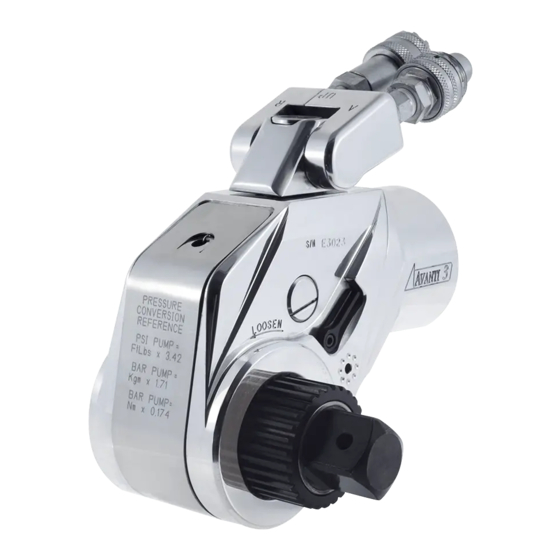
Intended use The Avanti hydraulic socket wrench is a tool used for both your torque and tension applications. Different reaction arms and sockets can be used with the tool. HYTORC hydraulic tools have an accuracy of ± 3%. Overview Electric pump unit 2. -
Page 14: Electric Pump Unit
Description Electric pump unit The pressure range of the pump unit is 50 bar - 700 bar. Hose connection (male coupling) (supply hose) (A) Pressure control valve / Wingnut Hose connection (female coupling) (re- turn hose) (B) Pressure relief valve Oil filling point Remote control Oil drain point... -
Page 15: Pneumatic Pump Unit
Description Pneumatic pump unit The pressure range of the pump unit is 50 bar - 700 bar. Hose connection (male coupling) (supply hose) (A) 2. Hose connection (female coupling) (re- turn hose) (B) 3. Oil filling point 4. Oil drain point 5. -
Page 16: Hydraulic Socket Wrench
Description Hydraulic socket wrench Hose connection (male coupling) (supply hose) (A) 2. Hose connection (female coupling) (re- turn hose) (R) 3. Square drive for socket connection 4. Disengagement lever for reaction pawl 5. Drive retainer 6. Spline for connection of reaction arm Mounting point for safety handle... -
Page 17: Accessories
Description Accessories 3.6.1 Safety handle Procedure For more convenience and safety, install the safety handle to the tool or the reaction arm. 3.6.2 BoltSafe load tester The BoltSafe load tester has a reading system and one or more sensors. The sensors monitor the bolt load in bolted joints. The sensors are shaped and used as a regular washer. - Page 18 Description...
-
Page 19: Installation
Installation Installation Hydraulic hoses The working pressure of the hydraulic hoses is up to 700 bar. The safety factor of the hydraulic hoses is factor 4. 4.1.1 Hydraulic hose connections Use a twin hose to connect the pump unit to the tool. A twin hose consists of two hoses. The supply hose has two ends with female couplings. - Page 20 Loosen the locking ring of the female coupling from the male coupling and pull the couplings apart. Toothed screw-type safety couplings (HYTORC 716) The coupling is identical to the screw-type safety couplings (type Pioneer), but both coupling are toothed. The male coupling has a toothed locking ring which is axially displaceable.
-
Page 21: Connecting The Hydraulic Hoses
Installation 4.1.2 Connecting the hydraulic hoses Warning: • Make sure that the system is depressurized. • Make sure that the hydraulic hoses are securely connected to both the pump unit and the tool. Make sure that there is no clearance between the male couplings and the female couplings. If the hydraulic hoses become loose, no hydraulic oil will flow through the hoses and the tool will not operate. -
Page 22: Power Supply (Electric Pump Units)
Installation Power supply (electric pump units) There are different types of electric pump units to operate the tool: 230V pump unit 2. 400V pump unit Warning: • Do not use an extension cable longer than necessary. • Make sure that the length of the extension cable does not exceed 50 metres. •... -
Page 23: Air Supply (Pneumatic Pump Units)
Explosion protection (pneumatic pump units) HYTORC can make the system (pump, hose and tool) explosion proof. The tools will be equipped with anodized swivels. Metal springs will be fitted onto the couplings of the swivel, the twin hose and the pump unit. The rubber feet of the pump unit will be replaced by metal studs. - Page 24 Installation...
-
Page 25: Reaction Arms
Reaction arms Reaction arms The reaction arms can be used together with hydraulic tools, pneumatic tools and electric tools. There are different types of reaction arms to operate the tool. Standard reaction arm (360°) The length of the reaction arm is fixed. One standard heavy-duty socket must be used together with the reaction arm. -
Page 26: Straight Tpf Reaction Arm
Reaction arms Straight TPF reaction arm The length of the reaction arm is adjustable. Two standard heavy-duty sockets must be used together with the reaction arm. Procedure Place the sockets over the nuts as far as possible. 2. Place the reaction arm as shown. 3. -
Page 27: Curved Wtct Reaction Arm With Reaction Pin Cup
Reaction arms Curved WTCT reaction arm with reaction pin cup The length of the reaction arm is adjustable. One standard heavy-duty hex socket must be used together with the reaction arm.. Procedure Place the male hex socket in the bolt head as far as possible. -
Page 28: Reaction Arm For Recessed Installation
Reaction arms Reaction arm for recessed installation 5.7.1 Fixed length The length of the reaction arm is fixed. One standard heavy-duty socket must be used together with the reaction arm. Procedure Place the socket over the nut as far as possible. 2. -
Page 29: Straight Dual-Tool Interconnect Reaction Arm
Reaction arms Straight dual-tool interconnect reaction arm The length of the reaction arm is adjustable. Two standard heavy-duty sockets must be used together with the reaction arm. Procedure For the lowest reaction force, choose a reaction point as far away as possible. 2. -
Page 30: 5.10 Multi-Tool Interconnect Reaction Arm
Reaction arms 5.10 Multi-tool interconnect reaction arm Multiple standard heavy-duty sockets must be used together with the reaction arm Procedure Place the sockets over the nuts as far as possible. 2. Place the reaction arm as shown. 3. Place the tools as shown 5.11 Reaction ring Multiple standard heavy-duty sockets must be used together with the reaction arm. -
Page 31: Reaction Strip (Recessed Bolt Heads)
2. Place the reaction arm as shown. 3. Place the tool as shown. 5.13 HYTORC Washer™ double-drive socket Procedure Place the HYTORC Washer™ under the regular nut. 2. Place the double-drive socket with the tool over the nut and reaction washer completely. -
Page 32: Hytorc Loaddisc™ Double-Drive Socket
3. Lock the double-drive socket with the tool onto the reaction washer using the locking lever. 5.15 HYTORC Nut™ drive The HYTORC Nut™ drive allows for 100% torsion-free axial bolt loading and converts the torque wrench into a mechanical tensioner. Procedure Replace the regular nut with the HYTORC Nut™. -
Page 33: Offset-Link
Reaction arms 5.16 Offset-link Procedure Place the offset-link over the nut. 2. Place the reaction arm as shown. 3. Place the tool as shown. - Page 34 Reaction arms...
-
Page 35: Securing The Sockets And Reaction Arms
Securing the sockets and reaction arms Securing the sockets and reaction arms Sockets and reaction arms must be secured to prevent injuries and damage to the equipment. There are different types of heavy-duty sockets to use with the tool: 6-point sockets / 12-point sockets (regular / high) 2. -
Page 36: Securing The Reaction Arm Onto The Spline Shaft
Securing the sockets and reaction arms Securing the reaction arm onto the spline shaft Procedure Slide the reaction arm (A) over the drive shaft (B) as shown. Make sure that the hex bolt (C) aligns with the hole (D). 2. Tighten the hex bolt (C) using a hex key. -
Page 37: Operation
200 bar (2,900 psi), 400 bar (5,800 psi) and 700 bar (10,000 psi) respectively. • all moving parts of the tool are clean and sufficiently lubricated with a high-quality NLGI #2 molybdenum disulfide grease. For subsea applications, HYTORC recommends Womi lube. • the square drive and the drive retainer are securely fitted. -
Page 38: Pneumatic Pump Unitt
Operation 7.2.2 Pneumatic pump unitt Procedure Set the on/off switch (A) to the on position to switch on the pump unit. 2. Press and hold the start button (B) to increase the pressure in the pump unit and operate the tool. 3. -
Page 39: Torque
Each HYTORC torque wrench has its own pressure/torque chart. The pressure/torque chart is separately supplied with your HYTORC torque wrench. Refer to the pressure/ torque chart to find the required torque (Nm / ft.lb.) and read the required pressure (bar / psi). -
Page 40: Setting The Torque
Operation 7.4.2 Setting the torque Warning: • Always set the pressure from low pressure to high pressure. Loosen the wingnut (A) on the pressure control valve (B) of the pump unit. 2. Turn the pressure control valve (B) counterclockwise to set the pressure as low as possible. -
Page 41: Direction Of Rotation
Operation Direction of rotation 7.5.1 Determining the direction of rotation Procedure To tighten a bolted connection, place the tool onto the bolt as shown. Refer to the marking “TIGHTEN” on the tool. 2. To loosen a bolted connection, place the tool onto the bolt as shown. -
Page 42: Tightening And Loosening A Bolted Flange Connection
Operation Tightening and loosening a bolted flange connection Warning: • When you use a hex socket, do not use more than the specified torque. • Place the tool with the socket on the nut or the bolt. Make sure that the socket is placed over the nut or the bolt as far as possible. -
Page 43: Loosening A Bolted Flange Connectionn
• Always set the pressure as low as possible to loosen the nut or the bolt. • If you must constantly use a high pressure to loosen the nut or the bolt, use a heavier HYTORC tool. Contact your local HYTORC representative for more information. - Page 44 Operation...
-
Page 45: Maintenance & Storage
• Clean dirty hose couplings. Replace defective hose couplings. • Replace the hydraulic oil when it has a white, milky look. Maintenance by HYTORC • Have the tool fully disassembled, cleaned, inspected and lubricated at least once a year. • When the tool is dirty because of sand or another abrasive, have the tool fully disassembled, cleaned, inspected and lubricated immediately. - Page 46 Maintenance & Storage...
-
Page 47: Troubleshooting
See Hydraulic hose connections on page 18. The male coupling and the female Use a HYTORC twin hose. coupling have been interchanged. The tool moves slower than usual. There is a leakage in the system. Adjust the pump pressure to 700 bar (10,000 psi) and switch off the pump unit while holding the start button. -
Page 48: Pump Units
Problem Possible cause Solution The pump pressure is not repeatedly The pressure control valve is dirty or Contact your local HYTORC accurate with a fixed setting. defective. representative. The pump unit operates and provides The hose couplings on the tool Securely tighten the female coupling pressure, but the tool does not move. -
Page 49: Electric Pump Units
See Power supply (electric pump units) on page 21. The motor operates, but the tool does The remote control cable is Contact your local HYTORC not make a complete stroke. damaged. representative. The valve block is defective. - Page 50 Troubleshooting...
-
Page 51: 10. Technical Data
Technical data 10. Technical data 10.1 Avanti p7 Drive 3/4” Radius (R) 25,0 mm 0,99” Length (L) 105,2 mm 4,14” Height (H) 106,9 mm 4,21” Width (W) 45,3 mm 1,79” Weight 1,4 kg 3,1 lbs. Maximum bolt load a) 271 kN 61.000 lbs. -
Page 52: Avanti 3
Technical data 10.3 Avanti 3 Drive 1” Radius (R) 38,1 mm 1,50” Length (L) 165,9 mm 6,53” Height (H) 160,2 mm 6,31” Width (W) 73,7 mm 2,90” Weight 4,3 kg 9,5 lbs. Maximum bolt load a) 787 kN 177.000 lbs. Minimum torque 604 Nm 445 ft.lbs. -
Page 53: Avanti 50
Technical data 10.6 Avanti 10 Drive 1 1/2” Radius (R) 60,3 mm 2,38” Length (L) 252,0 mm 9,92” Height (H) 236,0 mm 9,29” Width (W) 110,5 mm 4,35” Weight 13,3 kg 29,2 lbs. Maximum bolt load a) 1.601 kN 360.000 lbs. Minimum torque 2.388 Nm 1.761 ft.lbs. - Page 54 Technical data 10.9 Avanti 50 Drive 2 1/2” Radius (R) 100,3 mm 3,95” Length (L) 414,0 mm 16,30” Height (H) 356,4 mm 14,03” Width (W) 178,8 mm 7,04” Weight 57,1 kg 127,7 lbs. Maximum bolt load a) 4.359 kN 980.000 lbs. Minimum torque 9.764 Nm 7.202 ft.lbs.
-
Page 55: 10.12 Swivel Rotation
Note: The tool is not suitable for use in explosive environments. Your HYTORC deal- er is able to modify your HYTORC equipment (except for electric tools) to comply with the directives EPS 13 ATEX 2 561 X and EX II... -
Page 56: Maximum Torque Values
Technical data 10.14 Maximum torque values (hex drives and male hex sockets Maximum torque (Nm) Hex size (mm) Normal Break 1.020 1.612 1.768 2.500 2.775 2.950 3.600 4.000 4.800 7.480 8.296 9.928 10.880 16.320 17.952 20.400 22.440 30.600 33.592 43.520 47.736 Maximum torque (Nm) Hex size (mm) - Page 57 Technical data Note: If the area of the hex drive is smaller than the square drive, HYTORC will disclaim any liability for broken hex drives or hex sockets. These male hex sockets are excluded from warranty claims: • 1/2” x 17 mm (11/16”) and smaller •...
- Page 58 Technical data...
-
Page 59: Conformiteitsverklaring
Declaration of Conformity 11. Declaration of Conformity Declaration of Conformity (according to Annex II.1.A of the Machinery Directive) HYTORC BV Platinawerf 8, 6641 TL Beuningen Nederland declare under our own responsibility: We are the manufacturer of the Avanti hydraulic socket wrench with optional accessories.
Need help?
Do you have a question about the Avanti p7 and is the answer not in the manual?
Questions and answers