Table of Contents
Advertisement
Quick Links
Advertisement
Table of Contents

Related Manuals for Hytorc Stealth 2


Summary of Contents for Hytorc Stealth 2
- Page 1 Stealth hydraulic limited-clearance wrench Technical manual...
- Page 2 Details and values given in this manual are average values and have been compiled with care. Details and values are not binding. HYTORC disclaims any liability for damage or detriments suffered as a result of reliance on the information given...
-
Page 3: Table Of Contents
Contents Contents About the document.................6 Purpose of the document......................6 How to work with the document....................6 Languages........................... 6 Illustrations...........................6 Safety symbols in the document....................6 Related documents........................7 Revision history..........................7 Contact information........................7 Safety.......................8 General safety instructions......................8 2.1.1 Personnel.......................... 8 2.1.2 Work area..........................8 2.1.3 Equipment......................... - Page 4 6.7.1 Tightening a bolted flange connection................31 6.7.2 Loosening a bolted flange connection................31 Automatic shut-off system......................32 Thermal protection........................32 Maintenance..................33 Preventive maintenance......................33 Maintenance by HYTORC......................33 Storage....................34 Storing the cables........................34 Troubleshooting..................35 Tools............................35 Pump units..........................36 9.2.1 General...........................
- Page 5 Contents Declaration of Conformity..............43 Parts list....................44...
-
Page 6: About The Document
About the document About the document Purpose of the document The document shows the information to do these steps: • Install the equipment • Operate the equipment • Maintain the equipment The document contains the original instructions for the Stealth hydraulic limited-clearance wrench, to which is referred with the term ‘tool’. -
Page 7: Related Documents
Stealth hydraulic limited-clearance wrench User manual Revision history Date Revision number Comment 04-08-2016 First version Contact information HYTORC Nederland BV HYTORC Benelux BVBA Platinawerf 8 Ysselaarlaan 65B 6641 TL Beuningen 2630 Aartselaar The Netherlands Belgium Phone: +31 (0)24 3660660 Phone: +32 (0)38 705220 Website: www.hytorc.nl... -
Page 8: Safety
Only use the tools for the purposes for which they have been designed. Do not force small tools or accessories to do the job of a larger tool. HYTORC can develop customized accessories to ensure safe and simple operation. Contact your local HYTORC representative for more information. -
Page 9: Additional Safety Instructions
Metal-to-metal contact can cause sparks. Take appropriate additional measures. • Wear hearing protection. The sound emission of HYTORC pump units is less than 80 • Make sure that the maximum operating pressure of the pump unit is not higher than the maximum permitted pressure of 700 bar (10,000 psi). -
Page 10: Reaction Arms
Replace damaged hydraulic hoses immediately. Replace the hydraulic hoses at least every three years. 2.2.4 Reaction arms • Only use HYTORC reaction arms. • Do not modify the reaction arms in any way. • Place the reaction arm against a solid reaction point that can handle the load. -
Page 11: Safety Symbols On The Tool
Liability HYTORC cannot be held responsible for injury or damage that results from unintended use of the equipment. The equipment is designed and intended only for the purpose described in the relevant documents. Uses not described in the relevant documents are considered unintended uses and can result in injury or damage. -
Page 12: Description
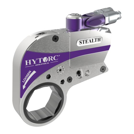
The Stealth hydraulic limited-clearance wrench is a tool used for both your torque and tension applications. Different reaction arms and sockets can be used with the tool. HYTORC hydraulic tools have an accuracy of ± 3%. Overview Electric pump unit... -
Page 13: Electric Pump Unit
Description Electric pump unit The pressure range of the pump unit is 50 bar - 700 bar. Hose connection (male coupling) (supply Pressure relief valve hose) (A) Hose connection (female coupling) (re- Remote control turn hose) (B) Oil filling point 10 Start button Oil drain point 11 Stop button... -
Page 14: Pneumatic Pump Unit
Description Indication Description Green, continuous The pump unit is ready for use. 400V pump unit Indication Description Green, continuous The pump unit is ready for use. Red, flashing (2x) The direction of rotation is incorrect. Reverse the polarity of the phase inverter plug. Red, continuous Error. -
Page 15: Hydraulic Limited-Clearance Wrench
Disengagement button for reaction pawl hose) (A) Hose connection (female coupling) (re- Mounting point for safety handle turn hose) (R) Ratchet link (interchangeable) Mounting holes for holding plate Link release button Hex drive or Hytorc nut drive Link pin 37 - 001 -... -
Page 16: Accessories
Description Accessories 3.6.1 Safety handle Procedure For more convenience and safety, install the safety handle to the tool or the reaction arm. 3.6.2 BoltSafe load tester The BoltSafe load tester has a reading system and one or more sensors. The sensors monitor the bolt load in bolted joints. -
Page 17: Insert
Description Procedure 3.6.4 Insert Procedure Place the adapter in the tool. Place the adapter over the nut as far as possible. 37 - 001 -... -
Page 18: Stacking Nuthead
Description 3.6.5 Stacking nuthead Procedure Place the adapter in the tool. Use the circlip ring to fasten the adapter. Place the adapter over the nut as far as possible. 3.6.6 Male hex drive Procedure Place the adapter in the tool. Use the circlip ring to fasten the adapter. -
Page 19: Installation
Installation Installation Hydraulic hoses The working pressure of the hydraulic hoses is up to 700 bar. The safety factor of the hydraulic hoses is factor 4. 4.1.1 Hydraulic hose connections Use a twin hose to connect the pump unit to the tool. A twin hose consists of two hoses. The supply hose has two ends with female couplings. -
Page 20: Connecting The Hydraulic Hoses
Loosen the locking ring of the female coupling from the male coupling and pull the couplings apart. Toothed screw-type safety couplings (HYTORC 716) The coupling is identical to the screw-type safe- ty couplings (type Pioneer), but both coupling are toothed. -
Page 21: Disconnecting The Hydraulic Hoses
Installation • Make sure that the hydraulic hoses are securely connected to both the pump unit and the tool. Make sure that there is no clearance between the male couplings and the female couplings. If the hydraulic hoses become loose, no hydraulic oil will flow through the hoses and the tool will not operate. -
Page 22: Power Supply (Electric Pump Units)
Installation Power supply (electric pump units) There are different types of electric pump units to operate the tool: 230V pump unit 400V pump unit Warning: • If you use an extension cable: • Do not use an extension cable longer than necessary. •... -
Page 23: Air Supply (Pneumatic Pump Units)
Explosion protection (pneumatic pump units) HYTORC can make the system (pump, hose and tool) explosion proof. The tools will be equipped with anodized swivels. Metal springs will be fitted onto the couplings of the swivel, the twin hose and the pump unit. The rubber feet of the pump unit will be replaced by metal studs. -
Page 24: Reaction Arms
Reaction arms Reaction arms The reaction arms can be used together with hydraulic tools, pneumatic tools and electric tools. There are different types of reaction arms to operate the tool. Reaction pad Procedure Place the reaction arm as shown. Place the tool over the nut as far as possible. -
Page 25: Interconnect Reaction Arm
Holding plate The holding plate allows to use double-drive. Multiple variants are available for use with the HYTORC Washer or HYTORC LoadDISC Procedure Place the HYTORC Washer HYTORC LoadDISC under the regular nut. Place the tool with the holding plate over the nut and reaction washer completely. -
Page 26: Operation
(5,800 psi) and 700 bar (10,000 psi) respectively. • all moving parts of the tool are clean and sufficiently lubricated with a high-quality NLGI #2 molybdenum disulfide grease. For subsea applications, HYTORC recommends Womi lube. • the square drive and the drive retainer are securely fitted. -
Page 27: Pneumatic Pump Unit
Operation 6.2.2 Pneumatic pump unit Procedure Set the on/off switch (A) to the on position to switch on the pump unit. Press and hold the start button (B) to increase the pressure in the pump unit and operate the tool. Set the on/off switch (A) to the off position to switch off the pump unit. -
Page 28: Torque
Operation Torque 6.4.1 Pressure/torque chart The maximum operating pressure for all HYTORC pump units is 690 bar (10,000 psi). Warning: • Make sure that the maximum operating pressure of the pump unit is not higher than the maximum permitted pressure of 690 bar (10,000 psi). -
Page 29: Replacing The Ratchet Link
Operation Press and hold the start button (C) on the remote control until the square drive no longer turns. The piston in the tool is in the fully extended position. Note: If the piston does not move, turn the pressure control valve (B) 360°... -
Page 30: Determining The Direction Of Rotation
Operation Determining the direction of rotation Procedure To tighten a bolted connection, place the tool onto the bolt as shown. Refer to the marking "TIGHTEN" on the tool. To loosen a bolted connection, place the tool onto the bolt as shown. -
Page 31: Tightening A Bolted Flange Connection
Always set the pressure as low as possible to loosen the nut or the bolt. • If you must constantly use a high pressure to loosen the nut or the bolt, use a heavier HYTORC tool. Contact your local HYTORC representative for more information. 37 - 001 -... -
Page 32: Automatic Shut-Off System
Operation Procedure Turn the pressure control valve (A) clockwise to set the maximum pressure (700 bar, 10,000 psi). If you use hex sockets, there are restrictions to make sure that the sockets do not break. Place the tool onto the nut or the bolt correctly. -
Page 33: Maintenance
• Clean dirty hose couplings. Replace defective hose couplings. • Replace the hydraulic oil when it has a white, milky look. Maintenance by HYTORC • Have the tool fully disassembled, cleaned, inspected and lubricated at least once a year. •... -
Page 34: Storage
Storage Storage Storing the cables Procedure Wind the remote control cable around the frame. Place the remote control in the remote control clamp. Electric pump unit: Wind the power supply cable around the frame. 37 - 001 -... -
Page 35: Troubleshooting
Troubleshooting Troubleshooting Try to find a solution for the problem using the tables. If you cannot find a solution for the problem, contact your local HYTORC representative. Tools Problem Possible cause Solution The tool does not move. The hose couplings on the tool... -
Page 36: Pump Units
General Problem Possible cause Solution The pump pressure is not re- The pressure control valve is Contact your local HYTORC peatedly accurate with a fixed dirty or defective. representative. setting. The pump unit operates and The hose couplings on the tool... -
Page 37: Pneumatic Pump Units
Power supply (electric The motor is overheated. The voltage is too low. pump units) on page 22. Con- tact your local HYTORC repre- sentative. 9.2.3 Pneumatic pump units Problem Possible cause Solution The pump does not build pres- The air supply is too low. -
Page 38: Technical Data
Technical data Technical data 10.1 Stealth 2 Length (L) 140.5 mm 5.53" Height (H) 106.9 mm 4.21" Width (W) 31.8 mm 1.25" Hex link, min 19 mm 3/4" Hex link, max 35 mm 1 3/8" Radius (R), min 26.1 mm 1.03"... -
Page 39: Stealth 8
Technical data 10.3 Stealth 8 Length (L) 203.2 mm 8.00" Height (H) 162.6 mm 6.40 " Width (W) 53.3 mm 2.10 " Hex link, min 44 mm 1-3/4" Hex link, max 64 mm 2-1/2" Radius (R), min 44.88 mm 1.77" Radius (R), max 73.4 mm 2.89"... -
Page 40: Swivel Rotation
Lighting normal ambient lighting Note: The tool is not suitable for use in explosive environments. Your HYTORC deal- er is able to modify your HYTORC equipment (except for electric tools) to comply with the directives EPS 13 ATEX 2 561 X and EX II 2 G EX c IIB T4. - Page 41 Technical data Maximum torque (Nm) Size (mm) Normal Break 1,020 1,612 1,768 2,500 2,775 2,950 3,600 4,000 4,800 7,480 8,296 9,928 10,880 16,320 17,952 20,400 22,440 30,600 33,592 43,520 47,736 Maximum torque (Nm) Size (inch) Normal Break 1,020 1,612 1,768 2,557 2,808 3,822...
- Page 42 Technical data Note: If the area of the hex drive is smaller than the ratch- et link drive, HYTORC will dis- claim any liability for broken stacking nutheads and hex drives. These male hex sock- ets are excluded from warran- ty claims: •...
-
Page 43: Declaration Of Conformity
Declaration of Conformity Declaration of Conformity Declaration of Conformity (according to Annex II.1.A of the Machinery Directive) HYTORC BV Platinawerf 8, 6641 TL Beuningen The Netherlands declare under our own responsibility: We are the manufacturer of the Stealth hydraulic limited-clearance wrench with optional accessories. -
Page 44: Parts List
Parts list Parts list Cylinder parts list Stealth-2 Stealth-4 Stealth-8 Stealth-14 Stealth-22 Stealth-36 Item QTY Description Housing assembly ST-02-01 ST-04-01 ST-08-01 ST-14-01 ST-22-01 ST-36-01 End cap with seal ST-02-02 ST-04-02 ST-08-02 ST-14-02 ST-22-02 ST-36-02 (top/bottom) Bottom piston rod ST-02-03 ST-04-03 ST-08-03 ST-14-03 ST-22-03... - Page 45 Parts list Stealth-2 Stealth-4 Stealth-8 Stealth-14 Stealth-22 Stealth-36 Item Qty Description Release pin kit ST-02-10 ST-04-10 ST-08-10 ST-14-10 ST-22-10 ST-36-10 Release pin ST-02-10 ST-04-10 ST-08-10 ST-14-10 ST-22-10 ST-36-10 Release dowl ST-02-10 ST-04-10 ST-08-10 ST-14-10 ST-22-10 ST-36-10 Release spring ST-02-10 ST-04-10 ST-08-10 ST-14-10 ST-22-10...
- Page 46 Parts list Link parts list Note: Replace the # in the part numbers with the link blank size. Stealth-2 Stealth-4 Stealth-8 Stealth-14 Stealth-22 Stealth-36 Item Qty Description Drive pawl pin ST-02-20 ST-04-20 ST-08-20 ST-14-20 ST-22-20 ST-36-20 Drive pawl assembly ST-02-21 ST-04-21 ST-08-21 ST-14-21...
- Page 47 Parts list Stealth-2 Stealth-4 Stealth-8 Stealth-14 Stealth-22 Stealth-36 Qty Description Side plate sleeve ST-02-29 ST-04-29 ST-08-29 ST-14-29 ST-22-29 ST-36-29 Slide, upper ST-02-30 ST-04-30 ST-08-30 ST-14-30 ST-22-30 ST-36-30 Slide, bottom ST-02-31 ST-04-31 ST-08-31 ST-14-31 ST-22-31 ST-36-31 Slide hook pin ST-02-32 ST-04-32 ST-08-32 ST-14-32 ST-22-32 ST-36-32 Roll pin, drive pawl ST-02-33 ST-04-33 ST-08-33 ST-14-33 ST-22-33 ST-36-33 spring...
Need help?
Do you have a question about the Stealth 2 and is the answer not in the manual?
Questions and answers