Table of Contents
Advertisement
Advertisement
Table of Contents

Related Manuals for Culligan Smart Controller HE DF 12


Summary of Contents for Culligan Smart Controller HE DF 12
- Page 1 Cat. No. 01024514 Rev. E 06/15/17 DCO # 017278 Installation, Operation, and Service Instructions with Parts Lists CULLIGAN ® High Efficiency 1.5 Water Filter Featuring the Culligan Smart Controller™ ® Models from 2012 ©2017 Culligan International Com pa ny...
- Page 2 Products manufactured and marketed by Culligan International Company (Culligan) and its affiliates are protected by patents issued or pending in the United States and other countries. Culligan reserves the right to change the specifications referred to in this literature at any time without prior notice. Culligan, Aqua-Sensor, Tripl-Hull, and SoftMinder are trademarks of Culligan International Company or its affiliates.
-
Page 3: Table Of Contents
Installation, Operation, and Service Instructions with Parts Lists CULLIGAN ® High Efficiency 1.5 Water Filter Featuring the Culligan Smart Controller™ ® Models from 2012 Contents Introduction ................ HE 1.5 Filter Parts List............. Basic Principles ..............Appendix A Data Port Output ........ - Page 4 Services Water Testing Made Easy. Culligan’s Analytical Laboratory provides its customers with quality water analysis using EPA approved methods. Our Analytical Laboratory is certified by the State of Illinois EPA, to be compliant with the National Environmental Laboratory Accreditation Conference (NELAC) standards. In addition to Illinois chemical certification, our Analytical Laboratory is certified to perform coliform and E.
-
Page 5: Introduction
The Culligan High Efficiency 1.5” Water Filters have been tested and certified by WQA and IAPMO against NSF/ANSI Standard 372, CSA B483.1, and NSF/ANSI Standard 61 for Materials Safety Re- quirements only. - Page 6 This publication is based on information available when approved for printing. Continuing design refinement could cause changes that may not be included in this publication. NOTE Do not remove or destroy the serial number. It must be referenced on request for warranty repair or replacement. Cat. No. 01024514 Culligan® High Efficiency 1.5 Water Filter...
-
Page 7: Basic Principles
Greensand Filter* Culligan’s standard Greensand Filters operate as a continuous feed system similiar to a depth filter and not as a batch style system. Greensand can remove manganese and both oxidized and soluble iron using a chlorine-injection feed system ahead of the filter. -
Page 8: Performance Specifications
In order to function properly, some operational parameters must be followed. They include: An operating water pressure between 20 and 125 psi (138-862 kPa). If water pressure is greater than 80 psi, Culligan recommends following the IAPMO Uniform Plumbing code section 806.2 by installing a Pressure Regulating Valve before the system. - Page 9 Culligan HE 1.5 Carbon Filter & Progressive Flow Carbon Filter HE CF 12 HE CF 14 HE CF 16 HE CF 21 Tank Size, in. [mm] 12x52 [305x1321] 14x47 [356x1194] 16x53 [406x1346] 21x62 [533x1575] Pipe Size, in. [mm] 1.5 [38.1] Temperature 33–120°F...
-
Page 10: Preparation
• Drain line, 1/2” (P/N 00303082, gray, semi-flexible; or P/N 00331946, black, semi-rigid; or equivalent) • Thread sealing tape • Pressure reducing valve (if pressure exceeds 125 psi [860 kPa]) • Pipe and fittings suited to the type of installation Cat. No. 01024514 Culligan® High Efficiency 1.5 Water Filter... - Page 11 Do not install the unit where it might freeze, or next to a water heater or furnace or in direct sunlight. Outdoor installation is not recommended and voids the warranty. Use the Culligan Outdoor HE filter for outdoor installations. The Culligan Out- door HE filter has been certified by Underwriter’s Laboratories for outdoor installation.
- Page 12 Recondition—A process where the media is revitalized to filter again. Media—The actual material that filters water. Underbedding—A gravel mixture that keeps the filter media from entering the distributors. Manifold Freeboard (C) Media Gravel Underbedding Distributor Figure 1. Media tank. Cat. No. 01024514 Culligan® High Efficiency 1.5 Water Filter...
-
Page 13: Controller Features
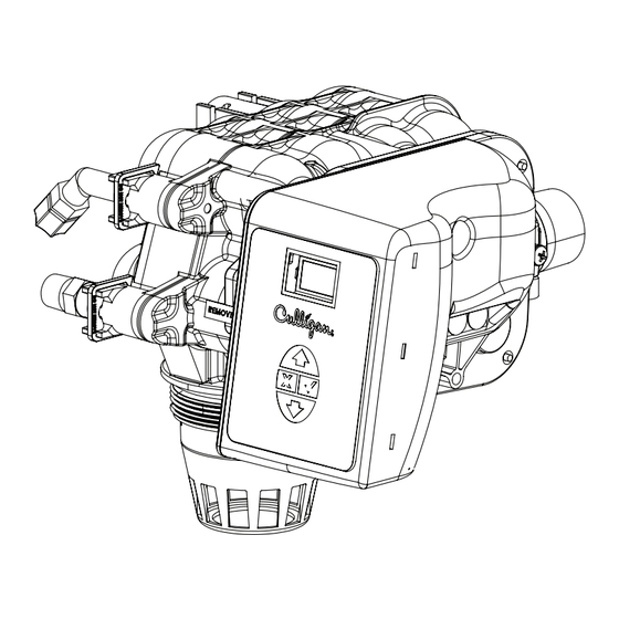
Culligan Smart Controller ™ The Culligan Smart Controller is designed to operate a wide range of existing and new High Efficiency softener and filtration valves. The Smart Controller is designed to be both reliable and easy to use. The Smart Controller features a bright and easy to read display. -
Page 14: Installation
Mark flush with tank opening Media Tank Remove distributor and cut square on mark Distributor Deburr distributor pipe Media Tank Rest flat on the bottom Figure 3. Install Distribution System Cat. No. 01024514 Culligan® High Efficiency 1.5 Water Filter... - Page 15 Loading the Media NOTE Do NOT attempt to load the media without having the tank in its final position. Moving the tank once the media has been loaded will be difficult at best. Cover the top of the distributor pipe with tape that will prevent media from entering the distributor. Use a funnel in the opening to add 6”...
- Page 16 Lower the control valve slowly onto the tank so that the distributor tube fits into the center of the control valve and then screw the control onto the tank. Figure 6. Mounting the control valve. Cat. No. 01024514 Culligan® High Efficiency 1.5 Water Filter...
- Page 17 Suggested Piping Installations The piping layouts below depict a traditional three-valve bypass. Culligan also offers an optional bypass valve that con- nects directly to the inlet and outlet of the water filter. NOTE Interconnecting pipe and fittings, bypass valves, and isolation valves are not supplied.
- Page 18 Figure 9. HE 1.5 filter cover fastener clip. Figure 10. Removing the HE 1.5 filter cover. Elbow Plug Clips Spacer Flow Control Drain Connector Figure 11. Replacing drain line flow control. Cat. No. 01024514 Culligan® High Efficiency 1.5 Water Filter...
- Page 19 Attaching the Cover Once the drain and brine line is connected re-attach the cover. Refer to the below instructions and Figure 12 through Figure 14. Insert the two pins on the top of the cover into the two holes on top of the frame; the cover should be slightly angled.
- Page 20 Straight-Through Adapter Each filter is shipped with a Culligan® straight-through adapter to connect the filter to the plumbing system. CAUTION! Close the inlet supply line and relieve the system pressure before cutting into the plumbing! Flooding could result if not done!
- Page 21 Optional Bypass Valve Installation Refer to Figure 16 and the instructions below to connect the meter, bypass valve, and interconnecting pipe. All HE units are equipped with a Soft-Minder meter. The meter is installed on the outlet side of the control ®...
- Page 22 CAUTION! Grip all connections to the circuit board by the connecting terminals for assembly and disassembly. Failure to do so could result in damage to the wire leads or connecting terminals. Cat. No. 01024514 Culligan® High Efficiency 1.5 Water Filter...
- Page 23 CAUTION! Do not touch any surfaces of the circuit board. Electrical static discharges might cause damage to the board. Handle the circuit board by holding only the edges of the circuit board. Mishandling of the circuit board will void the warranty. NOTE Observe all state and local electrical codes.
- Page 24 Tighten the nut on the interior side of the port opening on the controller enclosure. See Figure 24. Attach the female connector to the Smart Controller circuit board at the appropriate location. Bushing Nut Inside Controller Housing Figure 24. Connector bushing and nut position. Cat. No. 01024514 Culligan® High Efficiency 1.5 Water Filter...
- Page 25 NOTE The wire connectors must be connected to the circuit board properly. The wires must exit the plug-in connector opposite of the raised white base of the circuit board connector. Failure to properly connect any of the connectors will result in a malfunction of the circuit board operation. Connect the other end of the power cord, with the spade terminals, to the two 24 Volt terminals on the trans- former.
- Page 26 Refer to the GBE Programming for Commercial Softeners and Filters, except HF xN Manual (P/N 01027295) for programming information. This manual can be obtained from your local dealer, on C-Port (www.cport.culligan.com) under the Technical Service Tab or on the Service Tech App. Cat. No. 01024514 Culligan® High Efficiency 1.5 Water Filter...
-
Page 27: Smart Controller Circuit Board Layout
Smart Controller Circuit Board Layout Smart Controller Circuit Board Layout–Front OLED Display Battery CR2032 (Postitive Side Up) Pull protective tab before activating power to activate the battery Keypad connector Figure 27. Smart Controller circuit board layout, front view. Smart Controller Circuit Board Layout–Back Optional AUX 5 Relay Board Connection Data Port PLC Output... -
Page 28: Electrical Schematic
Electrical Schematic Cat. No. 01024514 Culligan® High Efficiency 1.5 Water Filter... -
Page 29: Installing Accessories
Internally blocked progressive flow is easier to install and maintain and has a lower total hardware cost compared to externally blocked progressive flow. Culligan recommends that all HE 1.5 progressive flow systems be set up as internally blocked systems. The only time when it is advantageous to use HE1.5 externally blocked progressive flow is: If the progressive flow system must use Upflow regeneration, then you must use externally blocked progressive flow. - Page 30 Attach Bracket to Valve To Siphon Break Attach the Blocking Solenoid Valve to the Bracket 1/8”NPT x 1/4” Tube Elbow* Drain Fitting Figure 30. Suggested piping and tubing for multi-tank systems. *Not supplied Cat. No. 01024514 Culligan® High Efficiency 1.5 Water Filter...
- Page 31 Sequence of Operation When a filter is in standby or a regeneration cycle, the GBE controller sends a signal to the Aux 4 terminal of the primary auxiliary board (see Figure 32), activating the solenoid valve. When the solenoid valve is electrically activated, ports #1 and #2 of the solenoid (Figure 31) become common.
- Page 32 Make sure the springs inside the control valve are centered inside the Progressive Flow U-Tube Adapa- ter. Insert the Progressive Flow U-Tube Adapter and mounting clips into the control valve. Figure 33. Progressive Flow U-Tube adapter. Cat. No. 01024514 Culligan® High Efficiency 1.5 Water Filter...
- Page 33 IMPORTANT—Setting the Jumpers for Progressive Flow For progressive flow to operate properly, the first and last units must have the jumpers set to pins 1 and 2 on terminal J22 (see Figure 34 at right). Jumper location for All middle units should have the jumpers on pins 2 and 3. The diagrams first and last units below (Figure 35 and Figure 36) show duplex connections.
- Page 34 Failure to do so can result in, at a minimum, damaging the GBE circuit boards. Culligan STRONGLY RECOMMENDS that every GBE circuit board be provided with its own individual power transformer as shown in Figure 37.
- Page 35 CORRECT FOUR INDIVIDUAL TRANSFORMERS NO NEED TO MATCH POLARITY BASE BOARD BASE BOARD BASE BOARD MODEM MODEM MODEM BOARD BOARD BOARD RF BOARD RF BOARD RF BOARD RJ11 RJ11 RJ11 PHONE PHONE PHONE AUXILARY BOARD AUXILARY BOARD AUXILARY BOARD ISOLATION ISOLATION ISOLATION RELAY...
- Page 36 DUPLEX ALTERNATING WITH EXTERNAL SOURCE Refer to GBE Programming for Commercial Softeners and Filters (except for HFxN) Manual (P/N 01027295) for program- ming information. This manual can be obtained from your local dealer, C-Port (www.cport.culligan.com) under the Techni- cal Service Tab or on the Service Tech App.
- Page 37 Figure 43. Auxiliary board activation timing. Refer to GBE Programming for Commercial Softeners and Filters (except for HFxN) Manual (P/N 01027295) for program- ming information. This manual can be obtained from your local dealer, C-Port (www.cport.culligan.com) under the Techni- EXAMPLE cal Service Tab or on the Service Tech App.
- Page 38 GBE board. Refer to GBE Programming for Commercial Softeners and Filters (except for HFxN) Manual (P/N 01027295) for program- ming information. This manual can be obtained from your local dealer, C-Port (www.cport.culligan.com) under the Techni- cal Service Tab or on the Service Tech App.
- Page 39 Program the remote and main monitor units using the instructions found in the GBE Programming for Commercial Softeners and Filters (except for HFxN) Manual (P/N 01027295). This manual can be obtained from your local dealer, C-Port (www.cport.culligan.com) under the Technical Service Tab or the Service Tech App.
- Page 40 (part number 01020747) into the socket on the back of the board. Make sure that all of the pins in all four connec- tors are aligned and make sure the modem is fully seated into all of the sockets. Figure 47. Back of GBE board. Cat. No. 01024514 Culligan® High Efficiency 1.5 Water Filter...
- Page 41 Back of remote board. Refer to the GBE Programming for Commercial Softeners and Filters, except HF xN Manual (P/N 01027295) for pro- gramming information. This manual can be obtained from your local dealer, on C-Port (www.cport.culligan.com) under the Technical Service Tab or on the Service Tech App.
- Page 42 Chemical Feed System For examples of components and chemical systems, please reference the Culligan Chemical Feed System Guid for the HE Controller (P/N 01024913), the Feeder and Mixer section of the Mechandise Catalog on C-Port (www.cport.culligan. com) or contact Culligan Application Engineering (call 1-877-216-6914 or email C&ISolutions@culligan.com).
- Page 43 Example Calculations for Diaphragm Pumps. This section contains a more detailed description of the Controller programming that will allow the use of other pumps, flow meters, and valves. Alternate chemical dosing pumps may be used with the system. Type 1 Chemical Dosing Pump (Diaphragm Pump) The Diaphragm pump performs as follows: • The pump delivers a specified volume of chemical each time the pump receives a dry contact closure.
- Page 44 • Option 2 - No dry contacts from External Source (bypass at a pre-programmed time each day) NOTE This feature is only available on HE single units (not available on HE 1.5” multi-tank units like Progres- sive Flow and Unbalanced Progressive Flow) Cat. No. 01024514 Culligan® High Efficiency 1.5 Water Filter...
- Page 45 (the HE unit goes back into service). Required Components • GBE Auxiliary Board (P/N 01020748) • Relay - Customer supplied (Culligan relay (P/N 01022238) can be used if the system has 24 VAC). WARNING! Disconnect all electrical power to the unit before servicing. CAUTION! Do not touch any surfaces of the circuit board.
- Page 46 Follow the programming procedure in the GBE Programming for Commercial Softeners and Filters, except HF xN Manual (P/N 01027295) to bypass the HE at a preset time. Figure 51. HE Automatic Bypass, Option 2 Cat. No. 01024514 Culligan® High Efficiency 1.5 Water Filter...
- Page 47 Separate Source Bypass Valve (Normally Closed) Filter Water Untreated Water Outlet Inlet BASE BOARD MODEM Manual Manual Inlet Valve BOARD Outlet Valve Inlet Valve (Normally Open) Vacuum Breaker RF BOARD RJ11 PHONE AUXILARY BOARD Regeneration Valve (Normally Closed) 24 V Valves Feed Drain...
-
Page 48: Final Startup
15. Initiate an immediate regeneration, or set to regenerate at the preset time. NOTE Unplugging the Culligan HE Series water filter will not affect any of the control settings. Once pro- grammed and powered on for at least 15 minutes, the settings will be stored indefinitely. - Page 49 Use only mild soap and warm water to clean the exterior of the unit. Never use harsh abrasive cleaners or com- pounds which contain acid or bleach. Culligan recommends Simple Green or an equivalent cleaner. Protect the conditioner and drain line from freezing temperatures.
-
Page 50: Preventative Maintenance
Suggested Preventative Maintenance Inspection Schedule The Culligan HE 1.5 commercial water filter has been designed to provide a good, consistent service life. Routinely inspecting the system may help avoid potentially costly breakdowns related to circumstances outside of the control of the dealer and/or user. -
Page 51: Maintenance
Refer to the GBE Programming for Commercial Softeners and Filters, except HF xN Manual (P/N 01027295) for diagnostic procedures using the Smart (GBE) Controller. This manual can be obtained from your local dealer, on C-Port (www.cport.culligan.com) under the Technical Service Tab or on the Service Tech App. - Page 52 Remove flow meter and 24 V connections. Remove the circuit board from the enclosure. Remove all connected wires from the board. To install a new circuit board, follow steps 1–5 in reverse order. Cat. No. 01024514 Culligan® High Efficiency 1.5 Water Filter...
- Page 53 Reprogram the circuit board. CAUTION! Do not touch any surfaces of the circuit board. Electrical static discharges may cause damage to the board. Handle the AccuSoft™ circuit board by holding only the edges of the circuit board. Keep replacement boards in their special anti-static bags until ready for use.
- Page 54 180 degrees and re-snap it; it should now be straight. Replace the gearbox by reversing the order of removing the gearbox. Figure 59. Pistons. Cat. No. 01024514 Culligan® High Efficiency 1.5 Water Filter...
-
Page 55: Troubleshooting
Troubleshooting Drain Line Flow Control—Service Located on the drain connection of the valve, the purpose of the drain line flow control is to regulate the up flow backwash required to expand and agitate the resin in the softener. The softener will allow maximum expansion of the resin, while preventing any loss to the drain. - Page 56 P1–Inlet Piston P2/P3–Outlet Piston P4–Backwash Piston P5–Rinse Piston P6–Bypass Piston Brine–Brine Piston P2/P3 PR–Refill Piston BRINE PISTON Figure 60. HE 1.5 valve piston locations. Regeneration Cycle Sequence Service Backwash Fast Rinse Refill Cat. No. 01024514 Culligan® High Efficiency 1.5 Water Filter...
- Page 57 Service Flow Raw water is allowed in the inlet to the top of the tank. The water is run through the resin up the manifold to the outlet. The water to the outlet should be soft if the system is operating properly. Tank Inlet Drain...
- Page 58 Water Brine Piston Brine Tank Tank Outlet Figure 62. Backwash flow. Backwash Piston Position P1–Inlet Closed P2/3–Outlet Open P4–Backwash Open P5–Rinse Closed P6–Bypass Piston Open Brine Piston Closed PR–Refill Piston Closed Cat. No. 01024514 Culligan® High Efficiency 1.5 Water Filter...
- Page 59 Fast Rinse Flow Backwash is followed by a fast flow of water down through the resin tank. The fast flow packs the resin bed and gets it ready for return to service. Tank Inlet Drain Water Brine Piston Brine Tank Tank Outlet Figure 63.
- Page 60 Water Brine Piston Brine Tank Tank Outlet Figure 64. Bypass flow. Bypass Piston Position P1–Inlet Closed P2/3–Outlet Closed P4–Backwash Closed P5–Rinse Closed P6–Bypass Piston Open Brine Piston Closed PR–Refill Piston Closed Cat. No. 01024514 Culligan® High Efficiency 1.5 Water Filter...
-
Page 61: He 1.5 Filter Parts List
HE 1.5 Filter Parts List HE 1.5 Filter Control Valve Assembly Cat. No. 01024514 HE 1.5 Filter Parts List... - Page 62 Enclosure w/ Decal and Keyboard (not — available for sale), Kit P0318383 SCREW, 10ea/Kit P1023122 Retainer,Screw, 10ea/Kit P1025274 Strain Relief Fitting, 10ea P1025277 Liquid Tight Hole Plug, 10ea/Kit 01025282 Harness,Meter,28" length 01017134 Power Cable,Gold Cat. No. 01024514 Culligan® High Efficiency 1.5 Water Filter...
- Page 63 Tank Assembly Figure 65. Tank assembly. Item No. Part No. Description Qty. A2365016 Tank, FRP, 12"x52" 01019578 Tank, FRP, 14"x47" 01019577 Tank, FRP, 16"x53" 01022256 Tank, FRP, 21"x62" 01011985 Manifold Kit, 12", 14", and 16" 01019618 Manifold Kit, 21" Cat. No. 01024514 HE 1.5 Filter Parts List...
- Page 64 01001345 (1) 01020797 (2) 01001296 (0.5) 00163811 (1) 01001345 (1) 01020797 (4) 01001296 (0.5) 00162110 (2) 00163811 (1) 01001345 (2) 01020797 (6) 01001296 (0.5) *Greensand filters are not WQA or IAMPO certified. Cat. No. 01024514 Culligan® High Efficiency 1.5 Water Filter...
- Page 65 Remote Display and Accessories Item Part Description 01020553 Remote Display Assembly, Softener/Fil- ter - 915 MHz, North American English Version D1025235 Remote Display Assembly, Softener/Fil- ter - 869 MHz, European English Version D1020608 Remote Display Assembly, Softener/Fil- ter - 869 MHz, European French Version D1025110 Remote Display Assembly, Softener/Fil- ter - 869 MHz, European Italian Version...
-
Page 66: Appendix A Data Port Output
If there were a ‘Replace Media Filter’, ‘Aquasensor Salt Err’ and ‘Motor Position Sensor Error’ present then bits 4, 6 and 8 would be set to 1 and all other bits would be 0, respectively. Cat. No. 01024514 Culligan® High Efficiency 1.5 Water Filter... - Page 67 Single softener section above. Electrical Connections The Culligan Data Cable Connector is terminated with a D-sub9 style female termination. The customer must provide the following pin connections:...
- Page 68 In order to connect the Smart Controller to a com- ® puter you will need a USB-to-GBE cable, Culligan P/N 01021507. You will also need to download a installation file from the myCulligan Web site on the GBE downloads page. The file is called “Setup_Culligan_GBE.EXE”. Once you copy the file to your PC, you can double-click on the file to install the USB drivers and the Data Port Output Viewer to your local hard drive.
-
Page 69: Index
Index Pin Connections Piping Accessories 25, Fast Rinse 3, Piston 50, Accessory Connections Filtering Process Power Supplies, 24VAC Alternating 13, Floor Surface Preparation Analyze the System Flow Control 14, Pressure Application Flow Diagrams Principles, Basic Application Problems Flow Restrictors Problems, Application Auxiliary Board Progressive Flow 25, 28, 29, Auxiliary Input... - Page 70 Notes Cat. No. 01024514 Culligan® High Efficiency 1.5 Water Filter...
- Page 71 This page contains materials and DCO in for ma tion. IT DOES NOT PRINT AS PART OF THE DOC U MENT! Materials & Description: High Efficiency 1.5 Filter Installation & Operation PN 01024514 Size: 8.5” x 11” Color: Black Ink, 2-sided Stock: Front (2-sided) &...
Need help?
Do you have a question about the Smart Controller HE DF 12 and is the answer not in the manual?
Questions and answers