
Related Manuals for Parker IPA Series


Summary of Contents for Parker IPA Series
- Page 1 IPA Intelligent Parker Amplifier Hardware Installation Guide Effective: December, 2014 Document Number: 88-032500-01A...
-
Page 3: User Information
Since Parker Hannifin constantly strives to improve all of its products, we reserve the right to change this guide, and software and hardware mentioned therein, at any time without notice. - Page 4 IMPORTANT USER INFORMATION Product Type: IPA Drive Controllers, including IPA04-HC and IPA15-HC The above product complies with the requirements of directives: EMC Directive 2004/108/EC Low Voltage Directive 2006/95/EC CE Marking Directive 93/68/EEC This product has been shown to meet the requirements of both UL61800-5-1UL508C as a Recognized Component, and the European Union CE requirements for Marking (93/68/EEC), Safety (IEC 61010-1 ed3.0 per 2006/95/EC Low Voltage Directive) and Electromagnetic Compatibility (IEC 61800-3 ed2.0 per 204/108/EC) when installed, operated and maintained as described in the product User Guide.
-
Page 5: Symbols
IMPORTANT USER INFORMATION Warning: Risk of damage and/or personal injury. The IPA described in this guide contains no user-serviceable parts. Attempting to open the case of any unit, or to replace any internal component, may result in damage to the unit and/or personal injury. This may also void the warranty. -
Page 6: Important Safety Information
The information in this user guide, including any apparatus, methods, techniques, and concepts described herein, are the proprietary property of Parker Hannifin or its licensors, and may not be copied disclosed, or used for any purpose not expressly authorized by the owner thereof. -
Page 7: Table Of Contents
TABLE OF CONTENTS Contents User Information ........................... 3 Contact Information for Technical Assistance ....................3 Symbols ..................................5 Description ................................5 Important Safety Information ....................6 Contents ............................7 CHAPTER 1 Introduction ......................14 IPA Controllers—Overview ....................15 IPA Product Description ............................15 IPA Part Numbers .............................. - Page 8 TABLE OF CONTENTS Cabinet Cooling Calculations ..........................20 Dimensions ..........................21 Drive Dimensions ..............................21 Weight ............................22 Mounting Guidelines ........................ 22 Cable Routing ................................22 Panel Routing ................................23 CHAPTER 3 Electrical Installation .................... 24 Installation Safety Requirements .................... 25 Precautions ................................
- Page 9 TABLE OF CONTENTS Inputs—General Purpose ............................. 40 Outputs—General Purpose ..........................40 X7 – Auxiliary (Control Power, Torque Enable, Analog Input) .......... 40 Output (Motor) Power ......................42 Output Power Ratings ............................42 Output (Motor) Power Connections ........................ 42 Power Supply ..........................43 Input Power................................
- Page 10 TABLE OF CONTENTS Regeneration Connection ............................. 52 Internal Regeneration Capability ......................... 53 CHAPTER 4 Communications ....................54 Overview ........................... 55 Ethernet Specifications ......................55 Ethernet Cable Specification ..........................55 Ethernet Connector ............................... 55 Ethernet Connector Pinout ........................... 56 RJ-45 LED Ethernet Status Indicators ......................56 Assigning IP Addresses ......................
- Page 11 TABLE OF CONTENTS Error Codes ................................69 Hall Sensors ................................72 Troubleshooting Checklist ..........................72 Possible Problems ............................. 72 Procedures ................................. 73 CHAPTER 6 Torque Enable Safety Circuitry ................78 Torque Enable Functional Description .................. 79 User Connections ........................80 Torque Enable Technical Specification ..................
- Page 12 TABLE OF CONTENTS Resetting the fault ............................. 88 Current Foldback ..............................88 Cables ............................89 EMC Ready Cables ..............................89 Non-EMC Cables ..............................89 CHAPTER 8 Regulatory Compliance UL and CE ..............90 System Installation Overview ....................91 General Safety Considerations ..........................91 General EMC Considerations ..........................
- Page 13 Software Configuration: Position Error & Soft Limits ............112 Software Configuration: End of Travel (EOT) Limits & Home ......... 113 APPENDIX C IPA with Parker Mechanics ................114 IPA with Parker Mechanics ....................115 Parker Gearhead Gear Ratios ........................... 118 Limit/Home Sensor Wiring ....................
-
Page 14: Chapter 1 Introduction
INTRODUCTION CHAPTER 1 Introduction 14 IPA Hardware Installation Guide... -
Page 15: Ipa Controllers-Overview
INTRODUCTION IPA Controllers—Overview The IPA is a single-axis drive/controller based on the IPA drive platform. Setup and programming is accomplished using the AcroBASIC language within the ACR-View programming environment. IPA Product Description The IPA is a single-axis digital servo drive with controller capability. The drive closes position, velocity, and torque loops, receiving its position setpoints from an internal servo controller. -
Page 16: Input Power Level
INTRODUCTION Input Power Level Model Number Description Motor Input Power IPA04-HC, IPA-15HC 120/240 VAC single-phase mains motor input power Control Input Power IPA04-HC, IPA-15HC 120/240 VAC single-phase mains motor input power Output Power Level Servo Motor Drives In the following table, the maximum current is given at 120/240 VAC input, which equates to a motor bus voltage of 170/340 VDC. -
Page 17: Checking Your Shipment
INTRODUCTION Checking Your Shipment Confirm that you have received all items in the table below. These items ship with the following drives: IPA. If you are missing an item, call the factory. For contact information, see Contact Information for Technical Assistance at the beginning of this guide. -
Page 18: Chapter 2 Mechanical Installation
MECHANICAL INSTALLATION CHAPTER 2 Mechanical Installation 18 IPA Hardware Installation Guide... -
Page 19: Environment & Drive Cooling
MECHANICAL INSTALLATION Environment & Drive Cooling The IPA drive operates in an ambient temperature range of 0°C (32°F) to 50°C (120°F) ambient air temperature. The drive can tolerate atmospheric pollution degree 2. Only dry, non-conductive pollution is acceptable. Therefore, it is recommended that the drive be mounted in a suitable enclosure. For drive cooling, you must install the drive so that the heat sink fins are vertical. -
Page 20: Cabinet Cooling
Power Dissipation for IPA (400 Watt Model) Shaft Power Voltage 200W 350W 120 VAC 240 VAC IPA15-HC Model The following values have been measured using the Parker MPM1421CSJXXXN motor. Power Dissipation for IPA Cabinet Cooling Calculations Shaft Power Voltage 700W 1300W 120 VAC 130W... -
Page 21: Dimensions
MECHANICAL INSTALLATION Dimensions There is one basic housing size, although the length of the heat sink fins varies with each model. This section contains the dimensions of all models. Drive Dimensions Figure 1. - IPA Drive Dimensions IPA Hardware Installation Guide 21... -
Page 22: Weight
MECHANICAL INSTALLATION Weight The following table lists the weight of each drive/controller model. Drive/Controller Weights Weight Drive/Controller pounds (kg) IPA04-HC 3.2 (1.5) IPA15-HC 3.7 (1.7) Mounting Guidelines The IPA is a vented product. To prevent material spilling into the drive, mount it under an overhang or in a suitable enclosure. -
Page 23: Panel Routing
MECHANICAL INSTALLATION Panel Routing The minimum clearance between IPA is 0.62 inches (15.75mm). The minimum clearance above and below a drive is 1 inch (25.4 mm). The following figure demonstrates these clearance requirements. Figure 2. - Panel Layout Dimensions for All IPA Models IPA Hardware Installation Guide 23... -
Page 24: Chapter 3 Electrical Installation
ELECTRICAL INSTALLATION CHAPTER 3 Electrical Installation 24 IPA Hardware Installation Guide... -
Page 25: Installation Safety Requirements
ELECTRICAL INSTALLATION Installation Safety Requirements IPAs meet the requirements of both the European LVD (Low Voltage Directive) and EMC (Electromagnetic Compliance) directives when installed according to the instructions given within “Chapter 8 Regulatory Compliance UL and CE.” As a rule, it is recommended that you install the drive/controller in an enclosure to protect it from atmospheric contaminants and to prevent operator access while power is applied. -
Page 26: System Installation Overview
ELECTRICAL INSTALLATION System Installation Overview This section details the components and configuration necessary for electrical installation of all models of the IPA. Installation of a motion control system requires an IPA, a compatible motor (listed on page 17), and access to a computer. -
Page 27: Connectors
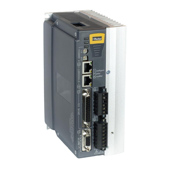
ELECTRICAL INSTALLATION Connectors All IPA models have the same set of connectors. Connector specifications are in this section and also “Chapter 7 Additional Specifications.” The following figure shows the name and location of the connectors. Auxiliary - X7 Torque Enable ... -
Page 28: X1 - Output Power Connector
ELECTRICAL INSTALLATION X1 – Output Power Connector The drive’s Motor screw terminal connector provides output power to the motor. For connection information, see “Output (Motor) Power” on page 42. The drive’s Motor connector provides terminals U, V, W and for connecting output power to the motor. It also serves to connect an external motor brake to the drive’s internal solid-state relay on the two BK terminals. -
Page 29: X2 - Input Power / Mains Connector
ELECTRICAL INSTALLATION X2 – Input Power / Mains Connector The Input Power / Mains connector contains terminals for external regeneration, control power, and motor power. Do not connect power to this connector before reading the section “Power Supply” on page 43. The Input Power / Mains connector provides terminals L1, L2, and for connecting motor mains power. -
Page 30: Factory Installed Jumpers
ELECTRICAL INSTALLATION Factory Installed Jumpers The IPA comes with external jumpers installed in the Input Power / Mains connector from C1 to L1, and C2 to L2. Figure 7 shows the location of the factory installed jumpers. Figure 7. - Factory-Installed Jumpers on Input Power/Mains Connector X6 –... -
Page 31: Motor Feedback Connector Pinout
Gold Flash—Amp Part Number 748333-7 Mating connectors are not provided with the drive. Parker cables are available with mating connectors attached. IMPORTANT: Encoder inputs use a DS26LV32 differential line receiver. Parker Hannifin recommends 26LS31 (or compatible) differential line driven encoders. -
Page 32: Internal Connections
ELECTRICAL INSTALLATION Internal Connections The following figure shows a schematic diagram of the internal connections for the Motor Feedback connector. Figure 9. - Internal Circuit Diagram for the Motor Feedback Connector Encoder Inputs Encoder input requirements are listed in the table below. Encoder Inputs Description Typical... -
Page 33: Motor Power & Feedback Cables
ELECTRICAL INSTALLATION Motor Power & Feedback Cables Parker cables are available with mating connectors attached for most Parker motors. Mating Cables for IPA to Parker Rotary Motors Motor Motor Cable Feedback Cable Feedback Cable Connector (incremental encoder) (EnDat absolute encoder) - Page 34 ELECTRICAL INSTALLATION Linear Servo Motor Power and Feedback Cables Motor Model Description Power Cable P/N TxxxxxxxxNxxLAx IForce & Ripped positioners with 006-1740-mm TxxxxxxxxNxxMAx connector box option, high flex TxxxxxxxxNxxZAx TxxxxxxxxNxxZAx 404LXRxxx Linear servo positioner with 006-1741-mm connector box, high flex 406LXRxxx Linear servo positioner with 006-1740-mm...
-
Page 35: X5 - Drive I/O Connector
ELECTRICAL INSTALLATION X5 – Drive I/O Connector The 25-pin Drive I/O connector has seven inputs and four outputs, which are described below. All drive input and output signals are optically isolated. Four general purpose inputs with both Anodes (+) and Cathodes (–) available ... -
Page 36: Drive I/O Cable
Note: VM25 Expansion Module available for easy access to IPA inputs and outputs. See “Appendix A.” For wiring of Parker Mechanics limit and home sensors, see “Appendix C.” Drive I/O Cable For preparing your own cable, use differential pair wiring with a minimum of three turns-per-inch (3 TPI). -
Page 37: Drive I/O Connector Pinout
ELECTRICAL INSTALLATION Drive I/O Connector Specification—Mating Connector Description Specification Connector Type 25-Pin D-Subminiature (male connector) Manufacturer AMP or equivalent 1658648-1 connector shield AMP Part Number Cable Kit enclosure 748474-1 includes: two jack screws (does not include contacts or ferrules) ... -
Page 38: Internal Connections
ELECTRICAL INSTALLATION Internal Connections The following figure shows a schematic diagram of the internal connections for the Drive I/O connector. Figure 12. - Internal Circuit Diagram for the Drive I/O Connector 38 IPA Hardware Installation Guide... -
Page 39: Inputs-High-Speed/Auxiliary Encoder
ELECTRICAL INSTALLATION Inputs—High-Speed/Auxiliary Encoder The high-speed inputs are optically isolated inputs. Current is limited internally for input voltage control of 5 to 24 volt logic. The Anode (+) and Cathode (−) optocoupler inputs are on separate connector pins to allow significant flexibility in wiring to different styles of interface. -
Page 40: Inputs-General Purpose
ELECTRICAL INSTALLATION Inputs—General Purpose These slow inputs are optically isolated. Current is limited internally for input voltage control of 5 to 24 volt logic. The Anode (+) and Cathode (−) optocoupler inputs are on separate connector pins to allow significant flexibility in wiring to different styles of interface. - Page 41 ELECTRICAL INSTALLATION Auxiliary Connector Specification Description Specification Connector Type 2x6 Pin 3.5mm male socket Manufacturer Phoenix (or equivalent) Phoenix Part Number 1787056 Auxiliary Connector Specification—Mating Connector Description Specification Connector Type 2x6 Pin 3.5mm female plug Manufacturer Phoenix or equivalent Phoenix Part Number 1790522 (black) or 1708577 (green) Signal Description...
-
Page 42: Output (Motor) Power
Figure 13. - Output Power Connection Current Parker motor cables are marked with white numbers (1, 2, or 3) to indicate the phase. Connect Motor Phase 1 to U, 2 to V, and 3 to W, and Motor Safety Earth to the Protective Earth ground connector. -
Page 43: Power Supply
ELECTRICAL INSTALLATION Power Supply IMPORTANT: Power to the IPA can be supplied in multiple ways. Completely read this section and comply with all safety measures before proceeding with connecting the unit to power. Input Power The mains Motor Power supply and the optional Control Power supply for the drive/controller must meet the requirements listed in the following table. -
Page 44: Control Power Fuse Information
ELECTRICAL INSTALLATION Control Power Fuse Information Each Control Power input line must be protected by the following fuse: Control Power Fuse Specification Description Specification Fuse Rating 1 Amp Class CC (Bussmann KTK-R-1 or Fuse Type equivalent UL listed fuse) Input Voltage Range 120/240 VAC, 50/60 Hz Input Current 0.2 Amps RMS... -
Page 45: Earth Ground
ELECTRICAL INSTALLATION Earth Ground Under normal operation, no current should flow through the Protective Earth connection. IMPORTANT: Make the Protective Earth ground connection directly by means of a low-impedance path less than or equal to 0.1 ohm (with no fuses or other devices). -
Page 46: Separate Sources Connections
ELECTRICAL INSTALLATION Separate Sources Connections Figure 15 shows how to connect separate external Motor and Control Power sources to the terminal connector installed in the drive. IMPORTANT: You must remove the factory installed jumper wires to use separate power sources. For more information on the jumpers, see “Factory Installed Jumpers”... -
Page 47: Multiple Drive/Controller Installations
Figure 16. Under normal operation, no current should flow through the Protective Earth ground. Safety Earth Connection For multiple drive installations, Parker Hannifin recommends a single point or “star” safety earth configuration. The following figure represents a typical star safety earth connection. -
Page 48: Brake Relay Connector (On Output Power Connector)
ELECTRICAL INSTALLATION Brake Relay Connector (on Output Power Connector) Description Connections Models IPA04, IPA15 Connector Type Removable screw terminal Terminals Pitch 0.200 in (5.08 mm) 12-26 AWG Wire range 14-27 SWG (0.12-3.30 mm2) Wire strip length 0.310 in (8 mm) Torque 7.0 in–lbs nom. -
Page 49: Brake Relay Connection
ELECTRICAL INSTALLATION Brake Relay Connection On all models, the two BK terminals are optically isolated from the drive/controller’s internal logic. Figure 17. - Typical Brake Relay Connection on the Output Power Connector Warning: You must connect the drive’s protective conductor terminal, marked with the earth symbol , to a reliable system Protective Earth. -
Page 50: Brake Relay To Motors With Full Wave Rectifiers
Brake Relay to Motors with Full Wave Rectifiers Newer Parker brake motors contain full wave rectifiers, so connection polarity is not an issue during installation. Older motors (BE, SM, NeoMetric, and J series motors, serial numbers less than 010904xxxxx) do not have rectifiers. -
Page 51: Brake Relay To Motors Without Full Wave Rectifiers
When using Parker MaxPlus motors, Parker motors with serial numbers less than 010904xxxxx, or non-Parker motors, you must install a fly-back diode. Consult the specifications or the manufacturer of your motor. Connect one red/blue brake wire (Parker Motor cable or equivalent) to one BK terminal (located on the Motor connector. -
Page 52: Regeneration Protection
ELECTRICAL INSTALLATION Regeneration Protection IPA04 and IPA15 do not have internal regeneration resistors for power dissipation; however, an external regeneration resistor can be used for this purpose. Regeneration Connection To use an external regeneration resistor, connect your external resistor to the R+ and R- terminals located on the Control Power connector. -
Page 53: Internal Regeneration Capability
ELECTRICAL INSTALLATION Internal Regeneration Capability The drive/controller may experience an over-voltage fault if the regeneration exceeds the absorbent capacity of the drive/controller’s internal bus capacitors, as shown in the following table. The available absorption varies, based on mains voltage and the drive/controller’s internal capacitance. The various drives can absorb the following amounts of regenerated energy in its internal capacitors. -
Page 54: Chapter 4 Communications
TROUBLESHOOTING CHAPTER 4 Communications 54 IPA Hardware Installation Guide... -
Page 55: Overview
TROUBLESHOOTING Overview The IPA communicates in a standard Ethernet network, thereby providing a direct link for sending commands through the ACR-View online help system installed on a PC. This chapter describes how to establish the standard Ethernet connection. All models of the drive/controller have a dual-stack, standard RJ-45 connector, which provides two communications ports. -
Page 56: Ethernet Connector Pinout
TROUBLESHOOTING Ethernet Connector Pinout The following table contains the Ethernet connector pinout. RJ-45 Connector Pinout Signal Wire Color Description White with orange Differential Receive positive side Orange Differential Receive negative side White with green Differential Transmit positive side Blue Not used White with blue Not used Green... -
Page 57: Setting The Ip Address And Subnet Mask-Pc
TROUBLESHOOTING Before adding the IPA to the network, complete its IP address by setting the last octet (digits) of the IP address on the rotary decimal switches. The last octet can be any number from 01 through 99 (00 is not valid). One rotary switch is marked S1 and the other S10. - Page 58 TROUBLESHOOTING Figure 22. - Control Panel Screen Click Network and Sharing Center. Figure 23. - Network and Internet Screen Click Local Area Connection. 58 IPA Hardware Installation Guide...
- Page 59 TROUBLESHOOTING Figure 24. - Network and Sharing Center Screen Click Properties. Figure 25. - Local Area Connection Status Screen Select Internet Protocol Version 4 (TCP/IPv4) and click Properties. IPA Hardware Installation Guide 59...
-
Page 60: Connecting To A Pc
TROUBLESHOOTING Figure 26. - Local Area Connection Properties Screen Click the radio button next to Use the following IP address and type in an IP address with the same first three octets as the default IPA IP address (192.168.100). Set the last octet to a number different from the number you set with the Address Switches on the faceplate of the IPA. - Page 61 TROUBLESHOOTING In ACR-View, under IPA and Communications, click Ethernet. Then enter the IP address in the box to the right. In the dialog box, click Connect. In the Terminal Emulator, type VER. If the Ethernet is set up correctly, the terminal emulator reports the firmware version information for the IPA.
-
Page 62: Led Status Indicators
TROUBLESHOOTING LED Status Indicators Ethernet Network Status The drive has one bi-color LED on the left of the front panel that indicates Ethernet status. It displays green or yellow colors. The following figure shows the location of the LED on the unit. Drive/Controller Status Ethernet Network... -
Page 63: Chapter 5 Troubleshooting
TROUBLESHOOTING CHAPTER 5 Troubleshooting IPA Hardware Installation Guide 63... -
Page 64: General Troubleshooting Guidelines
TROUBLESHOOTING General Troubleshooting Guidelines The IPA design features easy connectivity, auto-detect functions, and reliability. In addition, LEDs on the front panel of the unit provide quick identification of AC power, drive, and Ethernet status. If, after following the installation guidelines in Chapter 2, 3, and 4, your drive/controller does not function properly, use the guidelines and procedures in this chapter to troubleshoot. -
Page 65: Communications
TROUBLESHOOTING Communications All drive/controller communications are based on Ethernet. The IPA may be connected directly to any appropriately configured Ethernet port. The drive IP address will be 192.168.100.xx, where xx is defined by the address selection switches on the unit’s front panel. RJ-45 Ethernet Status LEDs The first step in troubleshooting communications is to observe the state of the RJ-45 Ethernet Status LEDs. -
Page 66: Ethernet Network Status Led
TROUBLESHOOTING If neither RJ-45 Ethernet Status LED is illuminated, the physical Ethernet connection is faulty. Verify that you are using the correct type of cable. See “Ethernet Cable Specification” on page 55. Verify that the cable pinout matches the drive’s connector pin out. See “Ethernet Connector” on page 55. Try swapping cables with Ethernet cables you know to be good. -
Page 67: Acr-View
View on the computer system connected to your drive/controller. Open the Configuration Wizard. Set the drive motor combination used. If you are not using a standard Parker motor, then check the box next to “I want to edit the mechanical/electrical parameters for my motor (Advanced).”... -
Page 68: Motor Control
TROUBLESHOOTING Motor Control The first step in troubleshooting motor-control issues is to examine the Drive/Controller Status LEDs (Figure 32). Use the following table to determine the indicated condition. Use the additional information in this section to take corrective action. On power-up, the LED pattern will flash through the various boot stages before settling into one of the patterns listed below. -
Page 69: Fault Correction
TROUBLESHOOTING Warning: When the top LED is Orange, the IPA is modifying the contents of flash. If power is cycled on the unit at this time, flash may be corrupted and the unit may need to be reprogrammed. Fault Correction To access further information on the drive status and fault conditions, use ACR-View on the computer system connected to your Ethernet network. - Page 70 TROUBLESHOOTING Error Resolution This parameter is set to zero (0). To correct the error, you must set a E8 Continuous Current = 0 non-zero value. Refer to your motor specifications for the correct value. (C1 Continuous Current) This parameter is set to zero (0). To correct the error, you must set a E9 Peak Current = 0 non-zero value.
- Page 71 TROUBLESHOOTING Error Resolution E32 Power Regeneration Fault Check the Regeneration resistor for a short. E34 Drive Temperature Fault Wait for the drive/controller to cool down. The motor thermal model has determined the motor is too hot. Wait for E35 Motor Thermal Model Fault the motor to cool, and then re-enable the drive/controller.
-
Page 72: Hall Sensors
TROUBLESHOOTING Hall Sensors The troubleshooting procedures in this section assume that a terminal emulator connection is established with the IPA. The procedures assist you in resolving a Hall fault (ERROR bit E37-Bad Hall State). Several problems can cause a Hall fault; the following checklist will help identify these problems. Troubleshooting Checklist Does THALL report either 0 or 7? If yes, see Problem 1 or Problem 2, below. -
Page 73: Procedures
TROUBLESHOOTING Problem 4 Either the motor wires or the Hall wires are connected incorrectly. Use Procedure 1—Motor Wires to fix this problem by changing the motor wires. Use Procedure 2—Hall Wires to fix this problem by changing the Hall wires. Problem 5 The Hall wires or the encoder wires may have loose connections, causing intermittent faults. - Page 74 TROUBLESHOOTING Safety High-performance motion control equipment is capable of Warning: producing rapid movement and very high forces. Unexpected motion may occur especially during the development of controller programs. KEEP WELL CLEAR of any machinery driven by stepper or servo motors. Never touch any part of the equipment while it is in operation.
- Page 75 TROUBLESHOOTING Warning: This procedure could damage the motor. Slowly increase the voltage until the motor moves. Do not exceed the rated current. Safety High-performance motion control equipment is capable of Warning: producing rapid movement and very high forces. Unexpected motion may occur especially during the development of controller programs.
- Page 76 TROUBLESHOOTING Figure 34. - Motor Terminal Voltages (back EMF) and Hall Sensor Signals 76 IPA Hardware Installation Guide...
-
Page 78: Chapter 6 Torque Enable Safety Circuitry
TORQUE ENABLE SAFETY CIRCUITRY CHAPTER 6 Torque Enable Safety Circuitry 78 IPA Hardware Installation Guide... -
Page 79: Torque Enable Functional Description
TORQUE ENABLE SAFETY CIRCUITRY Warning: THIS EQUIPMENT IF USED INCORRECTLY IS POTENTIALLY DANGEROUS. THEREFORE UNDER NO CIRCUMSTANCES SHOULD IT BE USED BEFORE THESE INSTRUCTIONS HAVE BEEN READ AND UNDERSTOOD BY THE END USER WHO SHOULD BE APPROPRIATELY QUALIFIED TO OPERATE THE EQUIPMENT. It is the user’s responsibility to: Risk assess the machine. -
Page 80: User Connections
TORQUE ENABLE SAFETY CIRCUITRY User Connections The Torque Enable terminals are on the Auxiliary connector mounted on the top of the IPA. Terminal designations are: Signal Description TRQ_EN1 Torque enable input 1 TRQ_EN2 Torque enable input 1 TRQ_EN_24V* Bypass power for TE (limited to 30mA) /TRQ_EN1 Negative input torque enable input 1 /TRQ_EN2... -
Page 81: Ideal Operation
TORQUE ENABLE SAFETY CIRCUITRY Truth Table State TRQ_EN1 TRQ_EN2 Drive Function Drive cannot start or supply power to the motor. Torque Disabled Torque Enable fault is reported. Drive cannot start or supply power to the motor. Torque Enable fault is reported. If condition exists for more than 3.0 seconds, the Torque Enable fault will Abnormal one lock and a Torque Enable Unhealthy state will be... -
Page 82: Typical Operation
TORQUE ENABLE SAFETY CIRCUITRY Typical Operation In typical operation, there can be a small time difference between changes of state on TRQ_EN1 and TRQ_EN2, due to different delays in the operation of two sets of relay contacts. TRQ_EN1 TRQ_EN2 <1.6s <1.6s States: Both inputs are low. - Page 83 TORQUE ENABLE SAFETY CIRCUITRY States: Both inputs are low. Hardware prevents the drive from starting. This is the torque disabled state of the drive. One input is high and the other input is low. Torque is disabled and prevents the drive from starting.
-
Page 84: Chapter 7 Additional Specifications
ADDITIONAL SPECIFICATIONS CHAPTER 7 Additional Specifications 84 IPA Hardware Installation Guide... -
Page 85: Amplifier
ADDITIONAL SPECIFICATIONS Amplifier Description Specification Control Power: all models 120/240 VAC (90-265 VAC) Single Phase Mains Control Power Single Phase AC Input, 120/240 VAC (90-265 VAC) 16 or 32 kHz switching Motor Power: all models frequency (motor dependent), pulse-width modulated (PWM) with 3-phase motor output Current Loop Update Rate 31.25 μs... -
Page 86: Resetting The Fault
ADDITIONAL SPECIFICATIONS Resetting the fault To clear the latched fault, choose one of the following methods: Cycle power to the drive/controller. –or– Open ACR-View and issue the DRIVE RES AXIS0 command to the IPA. Drive/Controller Over-Temperature Protection The IPA over-temperature circuit monitors the drive/controller’s internal temperature. If the sensors exceed the threshold temperature, the unit issues an over-temperature fault. -
Page 87: Under-Voltage Protection
Drive status word is updated via Ethernet to the PC (See the table “LED Under-Voltage Fault”) *Custom firmware may be used to lower this, such as for the MX80L. Contact your Parker ATC for customs. LED Under-Voltage Fault LED Middle... -
Page 88: Threshold Voltage
ADDITIONAL SPECIFICATIONS Threshold Voltage Description Specification All Models 410 VDC Power to motor is turned off Results of Fault Drive status word is updated via Ethernet to the PC (See the table “LED Over-Voltage Fault”) LED Over-Voltage Fault LED Left LED Right Yellow &... -
Page 89: Cables
Cables EMC Ready Cables Many Parker cables are EMC installation ready. If installed according to instructions provided under “A Highly- Immune, Low-Emission Installation – Meeting the Requirements of the Electromagnetic Compatibility (EMC) Directive” on page 93, these cables are designed to aid the user in gaining European Compliance, and are thus an integral part of a CE system solution. -
Page 90: Chapter 8 Regulatory Compliance Ul And Ce
REGULATORY COMPLIANCE UL AND CE CHAPTER 8 Regulatory Compliance UL and CE 90 IPA Hardware Installation Guide... -
Page 91: System Installation Overview
It should be stressed that although these recommendations are based on the expertise acquired during the design and development of the IPA products, and on tests carried out on similar products, it is impossible for Parker to guarantee compliance of any particular installation. Compliance will be strongly influenced by the physical and electrical details of the installation and the performance of other system components. -
Page 92: Installing The Ipa Drive
REGULATORY COMPLIANCE UL AND CE Installing the IPA Drive Only qualified, skilled electrical technicians familiar with local safety requirements should install this product. For service, the drive must be returned to an authorized service center. There are no user serviceable parts inside the chassis. -
Page 93: A Highly-Immune, Low-Emission Installation - Meeting The Requirements Of The Electromagnetic Compatibility (Emc) Directive
REGULATORY COMPLIANCE UL AND CE A Highly-Immune, Low-Emission Installation – Meeting the Requirements of the Electromagnetic Compatibility (EMC) Directive The following information was compiled to aid the machine builder or systems integrator in gaining EMC compliance. For effective control of Conducted and Radiated Emissions, along with maximizing the IPA Drive’s inherent noise immunity, the following recommendations should be followed. - Page 94 REGULATORY COMPLIANCE UL AND CE Figure 36. - 360° Bonding Techniques All braid termination connections must remain secure. For small diameter cables, it may be necessary to fold back the braid to increase the effective diameter of the cable so that R-Clamps are secure. Within the cabinet itself, all the motor cables should lie in the same trunking as far as possible.
-
Page 95: Control Power
Manufacturer FN670-3/06 Schaffner 6EP1 (160937-5) Corcom 10EP1 (160937-7) Corcom FN2070-10/06 Schaffner 1. Available from Parker: 10 Amp filter—part number 47-016140-01 Mains Motor Power Mains Motor Power Filter Selection Filter Continuous Current (Amps) IPA04-HC IPA15-HC 6EP1 (160937-5) 5 at 240 VAC... - Page 96 Cables may require the use of ferrite core suppressors. Some installations may require that you take additional EMC measures. To further increase product immunity and reduce product emissions, you may add clip- on ferrite absorbers to all cables. Parker recommends ferrites with at least 200 ohm impedance at 100 MHz, such as the following:...
-
Page 97: Panel Installation, Ipa04-Hc To Ipa15-Hc
REGULATORY COMPLIANCE UL AND CE Panel Installation, IPA04-HC to IPA15-HC Figure 37. - Typical LVD/EMC Installation, IPA04-HC to IPA15-HC Warning: This product has been developed for industrial environments. Due to exposed high voltage terminals, this product must not be accessible to users while under normal operation. IPA Hardware Installation Guide 97... -
Page 98: Panel Mounting
REGULATORY COMPLIANCE UL AND CE Panel Mounting The mounting clearance requirements are the same for all IPA drive models and are shown here: Figure 38. - Panel Layout Dimensions for the IPA Drive 98 IPA Hardware Installation Guide... -
Page 99: Regulatory Agencies
REGULATORY COMPLIANCE UL AND CE Regulatory Agencies The IPA family of products is designed to meet the requirements of global regulatory agencies. IPA products have shown compliance with the regulatory agencies in the following list. The list also shows additional steps users must take to ensure compliance. Agency Additional Steps User Must Take Mains fuses... - Page 100 REGULATORY COMPLIANCE UL AND CE 100 IPA Hardware Installation Guide...
-
Page 102: Appendix A Vm25 Expansion Module
APPENDIX A APPENDIX A VM25 Expansion Module 102 IPA Hardware Installation Guide... -
Page 103: Overview
APPENDIX A Overview The VM25 Expansion Module provides screwcage clamp terminal connections for input/output on the 25-pin Drive I/O connector. The VM25-MC-02 comes with a 2-foot cable that provides easy connection between the VM25 and the drive’s 25-pin connector. The VM25 has clips for DIN-rail mounting. The VM25 is ordered separately from the IPA (part number is “VM25-MC-02”). -
Page 104: Appendix B Ipa With Iforce Or Ripped Linear Servos
APPENDIX B APPENDIX B IPA with IForce or Ripped Linear Servos 104 IPA Hardware Installation Guide... -
Page 105: Iforce/Ripped To Ipa-Controller Wiring
The Ripped positioners (TR07, TR10, TR16) use HED connector modules that include both magnetic limits/home and hall-sensors feedback, and encoder readhead and scale. In 2008 Parker began changing wire color codes, both old and new are shown for reference. T1, T2, T3 Positioners/110, 210, 310 Coils with Options WD0/WD1/WD2/WD7... - Page 106 APPENDIX B Encoder, Hall and Thermal Sensor Connections Encoder Cable IPA Feedback Connector Note Function Signal Description Magnetic Optical Brown Brown +5 VDC +5 VDC Encoder power Ground White White DGND Encoder power return Yellow Yellow ENC A+ Encoder A Channel in Green Green ENC A–...
-
Page 107: Limit And Home Sensor Connections
APPENDIX B Limit and Home Sensor Connections IPA Thermal Model Protection and Power Installation The IPA uses a thermal model of the motor to estimate the coil temperature rise and is much faster than a thermal switch. If the internal thermal model is to be relied on to protect the motor, do not power off or reset the IPA during use. -
Page 108: Software Configuration: Select Coil Part Number
APPENDIX B Software Configuration: Select Coil Part Number The IForce and Ripped positioner part numbers contain the coil part numbers. Below shows an example of the IForce T2 positioner part number and the information pertinent for IPA configuration. 108 IPA Hardware Installation Guide... -
Page 109: Software Configuration: Set Feedback Resolution
APPENDIX B Simple pull-down selections in the ACR-View’s Configuration Wizard configure the amplifier based upon the motor part number. Ripped Example: Software Configuration: Set Feedback Resolution The Encoder’s Feedback Resolution sets the number of counts over an electrical cycle for the IPA to commutate. This is in the advanced motor parameters screen in ACR-View. - Page 110 APPENDIX B The R7-1 with 5um magnetic would be set to 8000 counts/electrical pitch. Note that the halls are inverted for both IForce and Ripped series coils for IPA configuration. Standard resolutions are listed below: Motor Series 0.5um 0.1um 110 / 210 / 310 12192 60960 121920...
-
Page 111: Software Configuration: Thermal Sensor Type
APPENDIX B Software Configuration: Thermal Sensor Type The thermal sensor type’s default setting of “Switch” and “Normally Closed Switch” are correct. IPA Hardware Installation Guide 111... -
Page 112: Software Configuration: Position Error & Soft Limits
APPENDIX B Software Configuration: Position Error & Soft Limits The (controller) Fault screen allows hardware limit switches to be enabled and the deceleration rate when a limit is detected. Software limits can also be enabled. The Maximum Position Error can also be set. For basic setup, set the maximum position errors to 10mm or 0.5 inch. -
Page 113: Software Configuration: End Of Travel (Eot) Limits & Home
APPENDIX B Software Configuration: End of Travel (EOT) Limits & Home Select the on-board input for positive limit. The Negative Limit will be the next input and the home the following. Note that for IForce and Ripped positioners, the home sensors are normally closed; change this screen’s default from Normally Open (NO) to Normally Closed (NC). -
Page 114: Appendix C Ipa With Parker Mechanics
APPENDIX C APPENDIX C IPA with Parker Mechanics 114 IPA Hardware Installation Guide... -
Page 115: Ipa With Parker Mechanics
IPA with Parker Mechanics Parker Mechanics are offered with a wide array of choices for limits and home sensors. Any of these combinations can be used with the IPA. The IPA can use either NPN (sinking) or PNP (sourcing) style sensors ranging from 5-24 VDC input levels. - Page 116 The IPA allows users to program moves in predefined units of measure. Simply enter the relevant parameters in ACR-View and the correct scaling factor will be calculated. Parker mechanics are offered in a wide range of ballscrew leads, transport belt sizes and gearhead ratios. The order codes and the actual leads are listed to the right for reference when using ACR-View.
- Page 117 APPENDIX C The above positioners and actuators do not include the optional gearbox reduction. IPA Hardware Installation Guide 117...
-
Page 118: Parker Gearhead Gear Ratios
APPENDIX C Parker Gearhead Gear Ratios Not all ratios are offered as standard in all models. Example: OSPE 32B with PV60TA-010 is 60mm/rev of the transport belt and the gearhead is a 10: ratio. Within the software, as the transport belt is in travel per rev and not pulley diameter use Transmission Type: Leadscrew to input 60mm and Gearbox input of 10, denominator of 1. - Page 119 APPENDIX C For inches, set the gearbox ratio to the ratio times 254 and set the denominator to 10. IPA Hardware Installation Guide 119...
-
Page 120: Limit/Home Sensor Wiring
APPENDIX C Limit/Home Sensor Wiring IForce and Ripped Positioners with Connector Box Option 400LXR Series Positioners Note: The IForce and Ripped positioned home sensor is Normally Closed (NC). 120 IPA Hardware Installation Guide... - Page 121 APPENDIX C Applies to the following Parker Stages: 402/403/404XE ...L12H11 404/406XR…L12H11 404/406/412LXR….H3 L2 IPA Hardware Installation Guide 121...
- Page 122 APPENDIX C Applies to the following Parker Stages: 404XE…H3L2 404XE…H7L6 401/402/404/406/412XR…H3L2 401/402/404/406/412XR…H7L6 122 IPA Hardware Installation Guide...
- Page 123 APPENDIX C Applies to the following Parker Stages: 404XE…H5L4 404XE…H9L8 401/402/404/406/412XR…H5L4 401/402/404/406/412XR…H9L8 IPA Hardware Installation Guide 123...
- Page 124 APPENDIX C Applies to the following Parker Stages: 402/403XE…H3L2 HD085/125/185…LH2 124 IPA Hardware Installation Guide...
- Page 125 APPENDIX C Applies to the following Parker Stages/Actuators: ET32/50/80/100/125 (Sensors (NPN) ordered separately) ETH, OSPE, LCR, LP28, HD (P8S Global Sensors (NPN) ordered separately) See page 127 for P8S Global sensors and page 128 for P8S Mini-Global sensors. IPA Hardware Installation Guide 125...
- Page 126 APPENDIX C ET32/50/80/100/125 PNP Sensors ordered separately ETH, OSPE, LCR, HD P8S Global Sensors (PNP) ordered separately See page 127 for P8S Global sensors and page 128 for P8S Mini-Global sensors. 126 IPA Hardware Installation Guide...
-
Page 127: P8S Global Drop-In Solid State Sensors
APPENDIX C P8S Global Drop-In Solid State Sensors PART# NPN/PNP N.O. / N.C. CABLE P8S-GNSHX* N.O. 0.2M with M8 003-3743-01 P8S-GNCHX N.O. 0.2M with M8 P8S-GPSHX* N.O. 0.2M with M8 003-3743-02 P8S-GPCHX N.O. 0.2M with M8 P8S-GMSHX* N.C. 0.2M with M8 003-3743-03 P8S-GMCHX N.C. -
Page 128: P8S Mini-Global Drop-In Solid State Sensors
APPENDIX C P8S Mini-Global Drop-In Solid State Sensors PART# NPN/PNP N.O. / N.C. CABLE P8S-MQFLX N.C. 3.0M FLY LEADS 003-4475-01 P8S-MQFLY N.C. 3.0M FLY LEADS P8S-MQSHX N.C. 0.3M with M8 003-4475-02 P8S-MQCHY N.C. 0.3M with M8 P8S-MMFLX N.C. 3.0M FLY LEADS 003-4475-03 P8S-MMFLY N.C.
Need help?
Do you have a question about the IPA Series and is the answer not in the manual?
Questions and answers