Sign In
Upload
Manuals
Brands
Parker Manuals
Controller
IPA04-HC
Parker IPA04-HC Manuals
Manuals and User Guides for Parker IPA04-HC. We have
1
Parker IPA04-HC manual available for free PDF download: Hardware Installation Manual
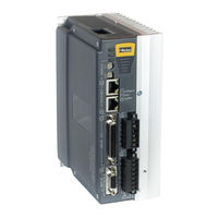
Parker IPA04-HC Hardware Installation Manual (128 pages)
Intelligent Amplifier
Brand:
Parker
| Category:
Controller
| Size: 4.62 MB
Table of Contents
User Information
3
Contact Information for Technical Assistance
3
Symbols
5
Description
5
Important Safety Information
6
Table of Contents
7
Contents
7
CHAPTER 1 Introduction
14
IPA Controllers-Overview
15
IPA Product Description
15
IPA Part Numbers
15
Input Power Level
16
Output Power Level
16
Servo Motor Drives
16
Components
16
Options
16
Checking Your Shipment
17
Illustrations in this Installation Guide
17
Assumptions of Technical Experience
17
Technical Support
17
CHAPTER 2 Mechanical Installation
18
Environment & Drive Cooling
19
Cabinet Cooling
20
IPA04-HC Model
20
IPA15-HC Model
20
Cabinet Cooling Calculations
20
Dimensions
21
Drive Dimensions
21
Weight
22
Mounting Guidelines
22
Cable Routing
22
Panel Routing
23
CHAPTER 3 Electrical Installation
24
Installation Safety Requirements
25
Precautions
25
System Installation Overview
26
Connectors
27
X1 - Output Power Connector
28
X2 - Input Power / Mains Connector
29
Factory Installed Jumpers
30
X6 - Motor Feedback Connector
30
Motor Feedback Connector Pinout
31
Internal Connections
32
Encoder Inputs
32
Motor Power & Feedback Cables
33
X5 - Drive I/O Connector
35
Sample Wiring
35
Drive I/O Cable
36
Drive I/O Connector Pinout
37
Internal Connections
38
Inputs-High-Speed/Auxiliary Encoder
39
Inputs-General Purpose
40
Outputs-General Purpose
40
X7 - Auxiliary (Control Power, Torque Enable, Analog Input)
40
Output (Motor) Power
42
Output Power Ratings
42
Output (Motor) Power Connections
42
Power Supply
43
Input Power
43
Fuse Requirements
43
Motor Power Fuse Information
43
Control Power Fuse Information
44
Drive Inrush Current
44
Power Supply Connections
44
Earth Ground
45
Single-Source (Motor Input Power) Connections
45
Separate Sources Connections
46
Multiple Drive/Controller Installations
47
Safety Earth Connection
47
Brake Relay (Optional)
47
Brake Relay Connector (on Output Power Connector)
48
Brake Relay Operation
48
Brake Relay Specifications
48
Brake Relay Connection
49
Brake Relay to Motors with Full Wave Rectifiers
50
Brake Relay to Motors Without Full Wave Rectifiers
51
Regeneration Protection
52
Regeneration Connection
52
Internal Regeneration Capability
53
CHAPTER 4 Communications
54
Overview
55
Ethernet Specifications
55
Ethernet Cable Specification
55
Ethernet Connector
55
Ethernet Connector Pinout
56
RJ-45 LED Ethernet Status Indicators
56
Assigning IP Addresses
56
Setting the IP Address- IPA
56
Setting the IP Address and Subnet Mask-PC
57
Connecting to a PC
60
Verifying the IP Address
60
LED Status Indicators
62
Ethernet Network Status
62
Drive/Controller Status
62
CHAPTER 5 Troubleshooting
63
General Troubleshooting Guidelines
64
Power
64
Communications
65
RJ-45 Ethernet Status Leds
65
Ethernet Network Status LED
66
ACR-View
67
Motor Control
68
Fault Correction
69
Error Codes
69
Hall Sensors
72
Troubleshooting Checklist
72
Possible Problems
72
Procedures
73
CHAPTER 6 Torque Enable Safety Circuitry
78
Torque Enable Functional Description
79
User Connections
80
Torque Enable Technical Specification
80
Ideal Operation
81
Typical Operation
82
Fault Operation
82
CHAPTER 7 Additional Specifications
84
Amplifier
85
Performance
85
Protective Circuits
85
Short Circuit Protection
85
Resetting the Fault
86
Drive/Controller Over-Temperature Protection
86
Threshold Temperature
86
Under-Voltage Protection
87
Threshold Voltage
87
Resetting the Fault
87
Over-Voltage Protection
87
Threshold Voltage
88
Resetting the Fault
88
Current Foldback
88
Cables
89
EMC Ready Cables
89
Non-EMC Cables
89
CHAPTER 8 Regulatory Compliance UL and CE
90
System Installation Overview
91
General Safety Considerations
91
General EMC Considerations
91
Installing the IPA Drive
92
Precautions
92
A Safe Installation - Meeting the Requirements of the Low Voltage Directive (LVD)
92
A Highly-Immune, Low-Emission Installation - Meeting the Requirements of the Electromagnetic Compatibility (EMC) Directive
93
Control Power
95
Mains Motor Power
95
Panel Installation, IPA04-HC to IPA15-HC
97
Panel Mounting
98
Regulatory Agencies
99
Standards of Compliance
99
APPENDIX A VM25 Expansion Module
102
Overview
103
APPENDIX B IPA with Iforce or Ripped Linear Servos
104
Iforce/Ripped to IPA-Controller Wiring
105
Limit and Home Sensor Connections
107
IPA Thermal Model Protection and Power Installation
107
Software Configuration: Select Coil Part Number
108
Software Configuration: Set Feedback Resolution
109
Software Configuration: Thermal Sensor Type
111
Software Configuration: Position Error & Soft Limits
112
Software Configuration: End of Travel (EOT) Limits & Home
113
APPENDIX C IPA with Parker Mechanics
114
IPA with Parker Mechanics
115
Parker Gearhead Gear Ratios
118
Limit/Home Sensor Wiring
120
Iforce and Ripped Positioners with Connector Box Option
120
P8S Global Drop-In Solid State Sensors
127
P8S Mini-Global Drop-In Solid State Sensors
128
Advertisement
Advertisement
Related Products
Parker IPA Series
Parker IPA-15HC
parker iqan-mc3
Parker IQAN-XA2
Parker IQAN-MC31
Parker IQAN-MC2
Parker IQAN-LST
Parker IQAN-XS2
Parker IQAN-XT2
Parker ICE090A4003501P50FF000000
Parker Categories
Controller
Control Unit
Industrial Equipment
Dryer
DC Drives
More Parker Manuals
Login
Sign In
OR
Sign in with Facebook
Sign in with Google
Upload manual
Upload from disk
Upload from URL