Table of Contents
Advertisement
Advertisement
Table of Contents

Related Manuals for Parker IQAN-MC31


Summary of Contents for Parker IQAN-MC31
- Page 1 IQAN-MC31 Instruction book Publ no HY33-8411-IB/UK Edition 2016-07-05...
-
Page 2: Table Of Contents
Appendix A ........... 32 IQAN-MC31 Technical Overview ....... . . 32 Appendix B . -
Page 3: Introduction
Contact the manufacturer if there is anything you are not sure about or if you have any questions regarding the product and its handling or maintenance. The term "manufacturer" refers to Parker Hannifin Corporation. Instruction book, IQAN... -
Page 4: Overview Of Relevant Documentation
Overview of relevant documentation Introduction Overview of relevant documentation The following publications are relevant for users of this product. The main documentation contains information that is not found elsewhere. The additional documentation contains product information in a compact format, for details on the information found in those documents, consult this manual. -
Page 5: Precautions
Read This Precautions Precautions Work on the hydraulics control electronics may only be carried out by trained personnel who are well-acquainted with the control system, the machine and its safety regulations. ARNING Make sure that you have sufficient knowledge before designing, modifiying or servicing the control system. - Page 6 Read This Precautions Start-up, maintenance, and diagnostics For all personnel carrying out installation, commissioning, maintenance or troubleshooting. ARNING Work on the hydraulics control electronics may only be carried out by trained personnel who are well-acquainted with the control system, the machine and its safety regulations.
-
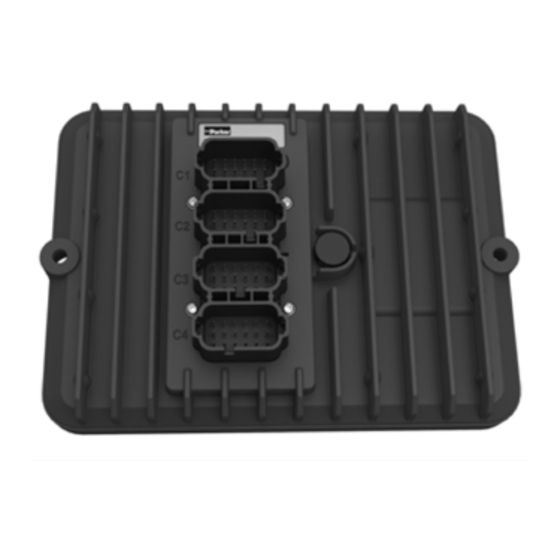
Page 7: Product Description
The IQAN-MC31 module. IQAN-MC31 origins The IQAN-MC31 is based on the IQAN-MC3 hardware but it has the safety functions removed in the operating software. This is done to enable bigger applications and a faster cycle time. - Page 8 (16) Voltage inputs VIN-A thru VIN-P Digital Inputs The IQAN-MC31 module also has sixteen (16) on/off inputs DIN-A thru DIN-P for switches. The inputs are multi-purpose and for flexibility may be configured in other ways. The input pins DIN-A thru DIN-H can be configured as frequency inputs for measuring frequency.
- Page 9 The communication interfaces are used for uploading/downloading applications or diagnostics and typically are connected to a computer. The IQAN-MC31 has 4 CAN buses. Either of the CAN buses may be used for communication and diagnostics. A CAN communication card is required to be installed in your PC to use this feature.
-
Page 10: Markings/Approvals
Markings/Approvals Product description Markings/Approvals Instruction book, IQAN-MC31... -
Page 11: Safety
Internal diagnostics Safety Safety Internal diagnostics The module performs a number of self-checks that improve safety. Checks include monitoring of voltage supplies, checksums on memory and a watchdog that monitors software execution. The module is using a real time operating system which supervises software execution. -
Page 12: Mounting
• For maximum cooling, mount the module on a vertical surface. • Locate the module so that the LEDs are visible. Recommended placing. OTICE The IQAN-MC31 module must not be placed in any marine related or similar continuously damp, salt-spray environment without external protection. Instruction book, IQAN... -
Page 13: Installation
CAN high voltage bus line, will be HIGH in dominant state. +BAT Power supply 12/24 Vdc +BAT Power supply 12/24 Vdc DOUT-I DOUT power driver, high side DOUT-N DOUT power driver, low side DOUT-J DOUT power driver, high side DOUT-O DOUT power driver, low side Instruction book, IQAN-MC31... - Page 14 Voltage signal input VIN-H Voltage signal input VIN-I Voltage signal input VIN-J Voltage signal input VIN-K Voltage signal input VIN-L Voltage signal input VIN-M Voltage signal input VIN-N Voltage signal input VIN-O Voltage signal input VIN-P Voltage signal input Instruction book, IQAN-MC31...
- Page 15 DIN / FIN / DFIN / PCN /DPCN signal input DIN-I Digital signal input DIN-J Digital signal input DIN-K Digital signal input DIN-L Digital signal input DIN-M Digital signal input DIN-N Digital signal input DIN-O Digital signal input DIN-P Digital signal input Instruction book, IQAN-MC31...
- Page 16 COUT power driver, low side DOUT-F DOUT power driver, high side DOUT-K DOUT power driver, low side DOUT-G DOUT power driver, high side DOUT-L DOUT power driver, low side DOUT-H DOUT power driver, high side DOUT-M DOUT power driver, low side Instruction book, IQAN-MC31...
-
Page 17: Supply Voltage
Supply voltage Supply voltage Before any installation of the IQAN system can take place, make sure the ignition lock is turned off and the battery is disconnected. Emergency stop Make sure an Emergency Stop disconnecting the power supply, is easily accessible at any time. -
Page 18: Addressing/Terminating
The maximum number of MC31 addresses is 8, denoted as addresses 0, 1, 2, 3, 4, 5, 6, 7 respectively. In order to assign any IQAN-MC31 an address , an ID-Tag will have to be connected to the positions ADDR-H and ADDR-L. -
Page 19: Diagnostic Interfaces
A high-speed CAN interface is needed to use this feature. Contact Parker for information about supported CAN interfaces. A termination resistor is usually required at the CAN interface on the PC. Parker part number 5030082 or 5030182, or an equivalent 120 ohm resistor may be used. A flying lead cable may be connected to the IQAN master to provide a connector interface. -
Page 20: Reference Voltage, Vref
Reference voltage, VREF Reference voltage, VREF The IQAN module is internally equipped with a voltage regulator to generate the reference voltage VREF. The standard reference voltage will feed different kinds of sensors and potentiometers. IQAN module +VREF -VREF VREF positions. OTICE It is strongly recommended to use the module’s -VREF and +VREF to all sensors and potentiometers that are connected to the module inputs. -
Page 21: Voltage Inputs
Voltage inputs Voltage inputs Connecting sensors to the voltage inputs The sensor signal range must be 0-5 Vdc. To detect signal errors such as short circuits or interruptions the active signal range be within 0.5-4.5 Vdc. Error detection range Active signal range Error detection range Active signal range. - Page 22 Voltage inputs Connecting a 2-wire temperature sensor to voltage in When you connect a PTC (positive temperature coefficient) temperature sensor you may need to use a pull up resistor on the input signal. Please check the technical data for your specific temperature sensor. EXAMPLE Connect the negative terminal of the temperature sensor to -VREF, and the signal to VIN-X.
- Page 23 Voltage inputs Connecting switches to the voltage inputs using +BAT It is recommended to connect system voltage +BAT to the input through a switch in order to reserve 5Vdc VREF for sensors and potentiometers. EXAMPLE Connect the positive and negative terminals of the switch to supply or the unit’s +BAT, and DIN-X, respectively.
-
Page 24: Digital Inputs
Digital inputs Digital inputs DIN that share pins with VIN These digital inputs share pins with the module voltage inputs and have high impedance characteristics. The preceding switch examples apply to these inputs. DIN that share pins with CRET These digital inputs share pins with the return pins of the proportional output channels, e.g. - Page 25 Digital inputs 2 The switch supply could be connected through a high impedance resistor. EXAMPLE Connect the supply of the switch to +BAT through a high impedance resistor, and the signal to DIN-X , respectively. +BAT IQAN module Resistor DIN-X, (shares RET pin) Switch Connecting a switch to DIN-X and supply through a resistor.
-
Page 26: Frequency Inputs
Frequency inputs Frequency inputs Connecting sensors to the frequency inputs Frequency inputs can operate in 2 modes. Speed which is frequency and position which is a pulse count. For the frequency ranges and trigger levels, see Appendix A. Simple frequency sensor The positive terminal of the frequency sensor is connected to the +VREF and the negative terminal to the -VREF respectively. -
Page 27: Proportional Outputs
Proportional outputs Proportional outputs The current /PWM outputs control proportional valves and devices. For the current range and loads, see Appendix A. Frequency To obtain the best performance from proportional valves the controller produces a PWM current mode (closed loop) output signal or a PWM voltage (open loop) output signal. -
Page 28: Digital Outputs
Digital outputs Digital outputs The digital outputs control relays and on/off valves. For the maximum load per output see Appendix A. Connecting loads to digital outputs Connecting of loads to the digital outputs such as on/off valves is done by using the DOUT positions and the negative battery terminal as ground. -
Page 29: Low-Side Digital Outputs
Low-side digital outputs Low-side digital outputs The low-side digital outputs may control relays and on/off valves. For the maximum load per output see Appendix A. Connecting loads to low-side digital outputs Connecting of loads to the low-side digital outputs such as on/off valves is done by using the DOUT(LS) positions and one or more DOUT channels as supply. -
Page 30: Diagnostic Digital Outputs
Diagnostic digital outputs Diagnostic digital outputs The IQAN-MC31 has two types of digital outputs. When used in pairs, high-side + low-side, diagnostics may be performed. DOUT A-E are the designations for the paired DOUT channels. DOUT-A = DOUT-F (HS) + DOUT-K (LS) and so on. For current ratings on the DOUT’s, see Appendix A. -
Page 31: Start-Up
Start-up procedures Start-up Start-up Start-up procedures This chapter contains instructions for action to be taken in connection with the initial start. ARNING Risk of injury! If the control system is not fitted properly, the machine could move uncontrollably. The machine’s engine shall not be started before the control system is completely fitted and its signals are verified. -
Page 32: System Diagnostics
System Diagnostics System Diagnostics The yellow blinking LED on the top of the module indicates normal status. If there is an error detected, the IQAN module will indicate error status through the red blinking LED. This gives an immediate diagnosis as to the nature of the error that has occurred. Yellow/ red, status LED The location of the LED indicators on the IQAN module. -
Page 33: Safe Mode
Safe mode Safe mode If the ADDR_L voltage > 3.00V (ADDR_L pin shorted to ADDR_H) is detected when the module starts (during power up) the application will not be loaded. This is a special start-up mode that is used for master modules and puts the unit in a safe state without starting any application. -
Page 34: Iqan-Mc31 Technical Overview
IQAN-MC31 Technical Overview Appendix A Appendix A IQAN-MC31 Technical Overview Absolute Maximum Ratings Ambient temperature, -40 to +85 °C Storage temperature -40 to +100 °C Voltage supply on +BAT 6 to 36 Vdc Voltage on any pin with respect to -BAT... - Page 35 IQAN-MC31 Technical Overview Appendix A System = -40 to +85 °C (unless otherwise specified) Weight 1.1 kg Ambient temperature, T -40 to +85 °C Voltage supply on +BAT, V 9 to 32 Vdc Current supply =14V typ. 250 mA typ. 170 mA...
- Page 36 IQAN-MC31 Technical Overview Appendix A Signal input, FIN/DFIN Number of FIN/DFIN 8/4 (configuration may reduce number) Frequency range 1 to 20,000 kHz, 50% duty cycle DFIN 1 to 20,000 kHz, 50% duty cycle Minimum pulse width 10 µs for 5 V signal...
- Page 37 IQAN-MC31 Technical Overview Appendix A Power driver, COUT Number of COUT 4 dual outputs COUT range 100 mA high 2000 mA COUT resolution 1 mA Power driver voltage drop 750 mA load typ. 0.45 V @ saturation 1500 mA load typ.
- Page 38 IQAN-MC31 Technical Overview Appendix A Power driver, DOUT Number of DOUT high-side low-side Maximum load DOUT-A to C (high-side) 3.0 A DOUT-D to E (high-side) 2.0 A DOUT-F to H (low-side) 3.0 A DOUT-I to J (low-side) 2.0 A Power driver voltage drop DOUT-A to C (high-side) typ.
-
Page 39: Error Codes, Messages And Actions
No application available Waiting for restart Error Error Primary Flash (red) Secondary Flash (yellow) code Error category Error description Output Input VREF Power supply Temperature Clock CAN, no contact IDtag error System mismatch CAN error (bus off) Internal error/OSE Instruction book, IQAN-MC31... -
Page 40: Dimensioning Of The Iqan-Mc31 Module
Dimensioning of the IQAN-MC31 module Appendix C Appendix C Dimensioning of the IQAN-MC31 module IQAN-MC3 Ø 6.5 Unit = mm Instruction book, IQAN-MC3... - Page 41 For the latest information visit our website www.iqan.com Information in this instructionbook is subject to change without notice Publ no HY33-8411-IB/UK Edition 2016-07-05 Parker Hannifin Parker Hannifin Electronic Controls Division Electronic Controls Division SE-435 35 Mölnlycke 1651 N. Main Street...
Need help?
Do you have a question about the IQAN-MC31 and is the answer not in the manual?
Questions and answers