
Related Manuals for Taylor C709


Summary of Contents for Taylor C709
- Page 1 OPERATOR’S MANUAL Model C709 and C717 Heat Treatment Soft Serve Freezers Original Operating Instructions 2/4/05 (Original Publication) 062080-M (Updated 11/8/2019)
- Page 2 Note: Only instructions originating from the factory or its authorized translation representative(s) are considered to be the original set of instructions. © February 2005, Taylor Company 062080-M Any unauthorized reproduction, disclosure, or distribution of copies by any person of any portion of this work may be...
-
Page 3: Table Of Contents
Model C709............4-1 Model C709 Single-Spout Door and Beater Assembly ......4-2 Model C717. - Page 4 Model C709 Freezer Door Assembly ........
-
Page 5: Section 1: To The Installer
® of Taylor machines. • Only Taylor service personnel should perform WARNING! This machine must NOT be installation, maintenance, and repairs on Taylor installed in an area where a water jet or hose can be machines. -
Page 6: Air-Cooled Machines
Air-Cooled Machines Electrical Connections Do not obstruct air intake and discharge openings: • C709—A minimum of 6 in. (152 mm) airspace is required on both sides and 0 in. (0 mm) on the rear. IMPORTANT! In the United States, this •... -
Page 7: Beater Rotation
If the supply cord is damaged, it must be replaced by a and skin protected. If refrigerant burns should occur, Taylor service technician to prevent a hazard. flush the area immediately with cold water. If burns are severe, apply ice packs and contact a physician Beater Rotation immediately. - Page 8 TO THE INSTALLER Notes: Models C709 & C717 To the Installer...
-
Page 9: Section 2: To The Operator
If you require technical assistance, please contact your local authorized Taylor distributor. Note: Your Taylor warranty is valid only if the parts are authorized Taylor parts, purchased from the local authorized Taylor distributor, and only if all required service work is provided by a Taylor service technician. -
Page 10: Compressor Warranty Disclaimer
FCC Compliance Statement: It should also be noted that Taylor does not warrant the • This equipment has been tested and found to comply refrigerant used in its machine. For example, if the... -
Page 11: Section 3: Safety
Safety Section 3 We at Taylor Company are concerned about the safety of the operator when he or she comes in contact with the freezer and its parts. Taylor has gone to extreme efforts WARNING! Avoid injury. to design and manufacture built-in safety features to •... - Page 12 Examples: Do not obstruct air intake and discharge openings: • Scraper blades • C709—A minimum of 6 in. (152 mm) airspace is • Condenser fins required on both sides and 0 in. on the rear. • Cup/cone dispenser (if applicable) •...
-
Page 13: Model C709
X59423 Pin-Retaining-Hopper CVR 043934 Panel A.-Front-Lower X58955 Kit A.-Cover-Hopper X65368 Stud-Nose Cone 055987 Blade A.-Agitator X56591 Shelf-Tray-Drip 056076 Tube A.-Feed-Outer-HT X34641 Tray-Drip 056858 Panel-Rear 056077-SP1 Shield-Splash 049203 Orifice 022465-100 Tube A.-Feed-SC-Inner X32824-2 Screw-1/4-20X3/8 RHM-SS 011694 Parts Models C709 & C717... -
Page 14: Model C709 Single-Spout Door And Beater Assembly
PARTS Model C709 Single-Spout Door and Beater Assembly Figure 4-2 Item Description Part No. Item Description Part No. Handle A.-Draw-Welded X56246 Pin-Handle-SS 055819 O-ring-1/4 OD X .070W 50 015872 Gasket-Door HT 4”-DBL 048926 Screw-Adjustment-5/16-24 056332 Bearing-Front 050216 Nut-Stud Black 3.250”... -
Page 15: Model C717
PARTS Model C717 Figure 4-3 Parts Models C709 & C717... - Page 16 Panel A.-Front Lower X59854-SER Pan-Drip 12.5 059736 Tray-Drip-19-5/8 L X 4-7/8 033812 Panel A.-Front (Middle) X63879 Pan-Drip 19-1/2 Long 035034 Stud-Nose Cone 055987 Panel-Corner-Front-Left 063088 Panel A.-Front (Upper) X59836 Panel-Side-Left 059906 Filter-Air-Poly-FLO 052779-11 Pin-Retaining-Hopper CVR 043934 Models C709 & C717 Parts...
-
Page 17: Model C717 Three-Spout Door And Beater Assembly
015872 Nut-Stud Black 2.563 Long 058764 Screw-Adjustment-5/16-24 056332 Bearing-Front 050216 Valve A.-Draw-L&R X59888 Beater A.-3.4 qt.-Helicore X31761 Valve A.-Draw-Center X59890 Blade-Scraper-Plastic 035174 O-ring-7/8 OD X .103W 014402 Shaft-Beater 032564 Seal-Draw Valve 034698 Seal-Drive Shaft 032560 Parts Models C709 & C717... -
Page 18: Feed Tube Assembly
Item Description Part No. Air Orifice 022465-100 O-ring - 291 ID x .080 W 018550 O-ring 016137 Tube A.-Feed-Outer-HT X34641 Tube A.-Feed-SC-Inner (C709) X32824-2 O-ring- .643 OD x .077 W 018572 Tube A.-Feed-SC-Inner (C717) X32824-3 Models C709 & C717 Parts... -
Page 19: Accessories
PARTS Accessories Apply the appropriate Taylor approved food safe lubricant. Figure 4-6 Item Description Part No. Item Description Part No. Pail-10 qt. 013163 Sanitizer-Stera Sheen 055492 Tool-O-ring Removal 048260-WHT Kit A.-Tune-Up (C709) X49463-92 Lubricant-Taylor Hi-Perf 048232 Kit A.-Tune-Up (C717) X49463-79 *Not Shown. -
Page 20: Brushes
Figure 4-7 Item Description Part No. Item Description Part No. Brush-Rear BRG 1” D X 2” L 013071 Brush-Mix Pump Body 3” X 7” 023316 Brush-Double Ended 013072 Brush-End-Door-Spout-SS 039719 Brush-Draw Valve 1”OD X 2 013073 Models C709 & C717 Parts... -
Page 21: Section 5: User Interface
User Interface C717 C709 Figure 5-1 Item Description Power Switch Liquid Crystal Display (LCD) Keypads Mix Out Indicator Standby Key Mix Low Indicator Select Key Service Menu Key Brush-Clean Counter Arrow Keys Topping Heater Key User Interface Models C709 & C717... -
Page 22: Symbol Definitions
During normal operation, the display is blank. The switches, function, and fault indicators. Your Taylor display is used to show menu options and notify the equipment is designed with these international symbols. -
Page 23: Operating Screen Descriptions
Manager's Menu is selected. The display screen also Reset Mechanism alerts the operator of specific faults detected by the The C709 reset button is in the service panel on the left control. side of the machine. The C717 reset buttons are in the Note: The displays illustrated in this section are those rear panel of the machine. - Page 24 HEAT CYCLE DATA menu option. on the VFD. An acknowledgment (SEL key) is required. The Heat cycle data records are checked for integrity when the record is accessed, but presently only through the HEAT CYCLE DATA menu option. Models C709 & C717 User Interface...
- Page 25 The holding phase keeps the temperature above 151°F (66.1°C) for a If the control is set for international configuration, the minimum of 35 minutes. following screen appears when the Heat key is pressed: User Interface Models C709 & C717...
-
Page 26: Freezer Locks
The FREEZER LOCKED message remains on the display until the brush-clean requirements are fulfilled. The freezer must be disassembled to activate the 5-minute timer on the display screen. Once the timer counts down to zero, the lockout is cleared. Models C709 & C717 User Interface... - Page 27 ON position. The during the Heat Treatment cycle: original message with the reason for the soft lock appears. HEAT TREAT FAILURE FREEZER LOCKED > HEAT FOR HEAT CYCLE WASH TO BRUSH CLEAN User Interface Models C709 & C717...
-
Page 28: Manager's Menu
There is a 2-minute timeout when you use the Manager's Menu. While in the Manager's Menu, if no activity occurs within a 2-minute period, the display exits to the main menu. One exception to this timeout is for the Current Conditions display. Models C709 & C717 User Interface... - Page 29 SET CLOCK • EXIT FROM MENU 12:01 6/10/2010 • SERVINGS COUNTER NO CHANGES ALLOWED • SET CLOCK Press Any Key • AUTO HEAT TIME • AUTO START TIME • AUTO STANDBY TIME • AGITATOR OPERATION User Interface Models C709 & C717...
- Page 30 00:00 the arrow next to “Change” displays the third screen. Change Press the Up or Down arrow key to move the arrow to the > Exit appropriate month for the start of DST. 5-10 Models C709 & C717 User Interface...
- Page 31 AUTO STANDBY TIME Program the auto start time by selecting the Up arrow 00:00 key to move the arrow to “Change.” Press the SEL key to advance to the next screen. AUTO START TIME 00:00 User Interface 5-11 Models C709 & C717...
-
Page 32: Faults
The most recent fault appears on are detected, the following screen appears. screen 1. The date, time, and fault description appears on each screen. FAULT DESCRIPTION NO FAULT FOUND FAULT HISTORY 00/00/00 00:00 REASON > Exit 5-12 Models C709 & C717 User Interface... - Page 33 Heat cycle. POWER FAIL IN H/C—A power failure occurred during the Heat Treatment cycle. MIX LOW FAILURE—The mix level in the hopper is too low for a successful Heat cycle. User Interface 5-13 Models C709 & C717...
- Page 34 Line 4 displays the time spent in the Heat and Cool phases for the barrel, and the peak barrel temperature through the entire Heat cycle. It also displays the amount of time that the barrel temperature was greater than the Hold temperature. 5-14 Models C709 & C717 User Interface...
-
Page 35: System Information
Manager Menu. Bootloader Once enabled, the gateway will start broadcasting its V1.13.000 access point. This will broadcast until the machine is paired with an Internet connection, or after a 10-minute > Next time-out. User Interface 5-15 Models C709 & C717... - Page 36 USER INTERFACE Notes: 5-16 Models C709 & C717 User Interface...
-
Page 37: Section 6: Operating Procedures
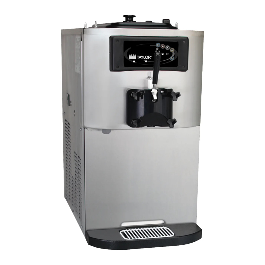
Operating Procedures Section 6 The C709 machine stores mix in a hopper. It has a 11269 3.4 qt. (3.2 L) freezing cylinder with a single-spout door. The C717 machine stores mix in two hoppers. It has two 3.4 qt. (3.2 L) freezing cylinders with a ... -
Page 38: Freezer Door Assembly
3. Repeat step 2 for the second scraper blade. Freezer Door Assembly 11097 The assembly of the C709 freezer door is different from the C717 freezer door. Follow the appropriate instructions for your machine. Model C709 Freezer Door Assembly 1. - Page 39 4. Insert the draw valve from the top, with the draw handle slot facing forward. Figure 6-10 Note: The C709 features an adjustable draw handle to provide portion control, giving a better consistent Apply the appropriate Taylor approved food safe lubricant.
-
Page 40: Model C717 Freezer Door Assembly
H-ring and O-rings. 10513 Figure 6-13 Apply the appropriate 2. Slide the front bearings over the baffle rods. The Taylor approved food safe lubricant. flanged edges should be against the door. Do not lubricate the gaskets or bearings. Figure 6-16 10512 Figure 6-14 Models C709 &... - Page 41 5 oz. to 7-1/2 oz. (142 g to 213 g) of product Apply the appropriate Taylor approved food safe lubricant. by weight per 10 seconds. To increase the flow rate, turn the adjustment screw clockwise.
-
Page 42: Feed Tube Assembly
3. Slide the small O-ring into the groove of the air 12029 orifice. 12077 Figure 6-26 Note: Since you sanitized the mix hopper and parts, Figure 6-24 make sure your hands are clean and sanitized. Models C709 & C717 Operating Procedures... - Page 43 Figure 6-30 Return to the freezer with a small amount of Apply the appropriate Taylor approved food safe lubricant. sanitizing solution. Dip the door spout brush into the sanitizing solution and brush-clean the door spout and bottom of the draw valve.
-
Page 44: Priming
4. Fill the hopper with fresh mix and place the mix ® hopper cover in position. cleaning/sanitizing solution (example Kay-5 5. Repeat steps 1 through 4 for the other side of ® Stera-Sheen Model C717. Models C709 & C717 Operating Procedures... - Page 45 Important! Do not attempt to draw product or disassemble the machine during the Heat cycle. The product is hot and under extreme pressure. When the Heating cycle is complete, the machine returns to Standby mode. The Standby key(s) illuminate. Operating Procedures Models C709 & C717...
-
Page 46: Daily Opening Procedures
Install the front drip tray and the splash shield. 6-10 Models C709 & C717 Operating Procedures... -
Page 47: Manual Brush-Cleaning
, canceling the Wash mode. Close the draw 5. Repeat steps 1 through 4 for the other side of valve. Model C717. 5. Repeat steps 1 through 4 for the other side of Model C717. Operating Procedures 6-11 Models C709 & C717... -
Page 48: Hopper Cleaning
3. Remove the scraper blades. 4. Remove the driveshaft seal from the driveshaft. 5. Remove the freezer door gasket, front bearing, pivot pin, draw handle, and draw valve. Remove the three O-rings from the draw valve. 6-12 Models C709 & C717 Operating Procedures... - Page 49 10014 Figure 6-42 6. Repeat steps 1 through 5 for the other side of Model C717. 7. Wipe all exterior surfaces of the freezer with a clean, sanitized towel. Operating Procedures 6-13 Models C709 & C717...
- Page 50 OPERATING PROCEDURES Notes: 6-14 Models C709 & C717 Operating Procedures...
-
Page 51: Section 7: Operator's Checklist
Too strong of a solution may damage the parts, and too weak of a solution does not adequately clean or sanitize. The temperature of mix in the mix hopper and walk-in cooler should be below 40°F (4.4°C). Operator’s Checklist Models C709 & C717... -
Page 52: Winter Storage
Disconnect the freezer from the main power source to It is recommended that a Taylor service technician prevent possible electrical damage. perform winter storage draining, to ensure all water has On water-cooled freezers, disconnect the water supply. -
Page 53: Section 8: Troubleshooting Guide
The freezer must be disassembled appears on display. and brush-cleaned within 24 hours when the counter indicates 1 day remaining. b. A barrel or hopper thermistor is b. Call a service technician. - - - faulty. Troubleshooting Guide Models C709 & C717... - Page 54 Lubricate properly or replace the 9. Product is collecting on a. The top O-ring on draw valve is top of the freezer door. improperly lubricated or worn. O-ring. Models C709 & C717 Troubleshooting Guide...
- Page 55 Fill the mix hopper with mix. into the freezing hopper. cylinder. b. The mix inlet hole is frozen up. b. The mix hopper temperature needs - - - adjustment. Call a service technician. Troubleshooting Guide Models C709 & C717...
- Page 56 TROUBLESHOOTING GUIDE Notes: Models C709 & C717 Troubleshooting Guide...
- Page 57 Inspect and replace if Minimum necessary. Black Bristle Brush, 1” x 2” Inspect and replace if Minimum necessary. Double-Ended Brush Inspect and replace if Minimum necessary. Yellow Bristle Brush Inspect and replace if Minimum necessary. Parts Replacement Schedule Models C709 & C717...
- Page 58 PARTS REPLACEMENT SCHEDULE Notes: Models C709 & C717 Parts Replacement Schedule...
- Page 59 LIMITED WARRANTY Taylor warrants the Product against failure due to defect in materials or workmanship under normal use and service as follows. All warranty periods begin on the date of original Product installation. If a part fails due to defect during the applicable warranty period, Taylor, through an authorized Taylor distributor or service agency, will provide a new or remanufactured part, at Taylor’s option, to replace the failed defective part at no charge for the part.
- Page 60 7. Failure, damage, or repairs due to faulty installation, misapplication, abuse, no or improper servicing, unauthorized alteration, or improper operation or use as indicated in the Taylor Operator’s Manual, including but not limited to the failure to use proper assembly and cleaning techniques, tools, or approved cleaning supplies.
- Page 61 LEGAL REMEDIES The owner must notify Taylor in writing, by certified or registered letter to the following address, of any defect or complaint with the Product, stating the defect or complaint and a specific request for repair, replacement, or other correction of the Product under warranty, mailed at least thirty (30) days before pursuing any legal rights or remedies.
- Page 62 LIMITED WARRANTY ON EQUIPMENT Notes: 10-4 Limited Warranty on Equipment Models C709 & C717...
- Page 63 Taylor warrants the Parts against failure due to defect in materials or workmanship under normal use and service as follows. All warranty periods begin on the date of original installation of the Part in the Taylor unit. If a Part fails due to defect during the applicable warranty period, Taylor, through an authorized Taylor distributor or service agency, will provide a new or remanufactured Part, at Taylor’s option, to replace the failed defective Part at no charge for the Part.
- Page 64 Taylor. 5. Replacement of wear items designated as Class “000” Parts in the Taylor Operator’s Manual, as well as any release sheets and clips for the Product’s upper platen assembly.
- Page 65 LEGAL REMEDIES The owner must notify Taylor in writing, by certified or registered letter to the following address, of any defect or complaint with the Part, stating the defect or complaint and a specific request for repair, replacement, or other correction of the Part under warranty, mailed at least thirty (30) days before pursuing any legal rights or remedies.
- Page 66 LIMITED WARRANTY ON PARTS Notes: 11-4 Limited Warranty on Parts Models C709 & C717...
Need help?
Do you have a question about the C709 and is the answer not in the manual?
Questions and answers