Table of Contents
Advertisement
UM1690
User manual
Discovery kit for STM32F0 Series microcontrollers
with STM32F072RB
Introduction
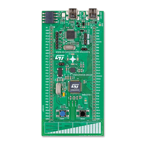
The STM32F072 Discovery kit (32F072BDISCOVERY) helps users to discover the full
features of the STM32F0 Series and develop their applications. It is based on an
STM32F072RBT6 microcontroller and includes an ST-LINK/V2 embedded debug tool
interface, ST MEMS gyroscope, LEDs, push-buttons, linear touch sensor, touch keys, RF
EEPROM connector and a USB Mini-B connector.
Figure 1. STM32F072 Discovery kit
Picture is not contractual.
March 2020
1/27
www.st.com
Advertisement
Table of Contents

Related Manuals for ST STM32F072


Summary of Contents for ST STM32F072
-
Page 1: Figure 1. Stm32F072 Discovery Kit
Discovery kit for STM32F0 Series microcontrollers with STM32F072RB Introduction The STM32F072 Discovery kit (32F072BDISCOVERY) helps users to discover the full features of the STM32F0 Series and develop their applications. It is based on an STM32F072RBT6 microcontroller and includes an ST-LINK/V2 embedded debug tool interface, ST MEMS gyroscope, LEDs, push-buttons, linear touch sensor, touch keys, RF EEPROM connector and a USB Mini-B connector. -
Page 2: Table Of Contents
Embedded ST-LINK/V2 ........ -
Page 3: Um1690 Rev
UM1690 Contents Mechanical drawing ........25 Revision history . - Page 4 List of tables UM1690 List of tables Table 1. Ordering information ............7 Table 2.
- Page 5 Figure 8. STM32F072 Discovery kit mechanical drawing ....... . . 25...
-
Page 6: Features
Extension header for LQFP64 I/Os for quick connection to a prototyping board and easy probing • On-board ST-LINK/V2 with switch to use the kit as a standalone ST-LINK/V2 (with SWD connector for programming and debugging) • Flexible power supply options: –... -
Page 7: Ordering Information
Any consequences arising from such usage will not be at ST’s charge. In no event will ST be liable for any customer usage of these engineering sample tools as reference designs or in production. -
Page 8: Development Environment
The demonstration software, included in the STM32Cube MCU Package, is preloaded in the STM32 Flash memory for easy demonstration of the device peripherals in standalone mode. The latest versions of the demonstration source code and associated documentation can be downloaded from the www.st.com/stm32f0-discovery webpage. Conventions Table 3 provides the definition of some conventions used in the present document. -
Page 9: Hardware Layout
UM1690 Hardware layout Hardware layout The STM32F072 Discovery kit is designed around the STM32F072RBT6 microcontroller in a 64-pin LQFP package. Figure 2 illustrates the connections between the STM32F072RBT6 and its peripherals (ST- LINK/V2, ST MEMS gyroscope I3G4250D, LEDs, push buttons, linear touch sensor, touch keys, RF EEPROM connector and a USB Mini-B connector). -
Page 10: Figure 3. Top Layout
Hardware layout UM1690 Figure 3. Top layout ST-LINK/V2 PWR LED USB ST-LINK USB USER COM LED CN3 extension or RF EEPROM connector 3 V power supply 5 V power supply input/output input/output SWD connector ST-LINK/DISCOVERY selector LD3 (red LED) LD5 (green LED) -
Page 11: Figure 4. Bottom Layout
UM1690 Hardware layout Figure 4. Bottom layout P2 connector P1 connector SB1, 3, 6, 8 Reserved SB2, 4, 7, 9 Default STM_RST SB10 SB11,12 NRST RX, TX SB15 VBAT SB19 SB13, 14 X2 crystal SB16 VDDIO2 SB17, 18 SB20, 23 X3 crystal USB-USER SB21 B1-USER... -
Page 12: Embedded St-Link/V2
5.1.1 Using ST-LINK/V2 to program/debug the STM32F072 on board To program the STM32F072 on board, simply plug in the two jumpers on CN5, as shown in Figure 5 in pink, but do not use the CN4 connector as that could disturb communication with the STM32F072RBT6 of the STM32F072 Discovery kit. -
Page 13: Using St-Link/V2 To Program/Debug An External Stm32 Application
Hardware layout 5.1.2 Using ST-LINK/V2 to program/debug an external STM32 application It is very easy to use the ST-LINK/V2 to program the STM32 on an external application. Simply remove the 2 jumpers from CN5 as shown in Figure 6, and connect the application... -
Page 14: Power Supply And Power Selection
5 V can also be used as input power supplies, for instance when the USB connector is not connected to the PC. In this case, the STM32F072 Discovery kit must be powered by a power supply unit or by an auxiliary equipment complying with standard EN-60950-1: 2006+A11/2009, and must be Safety Extra Low Voltage (SELV) with limited power capability. -
Page 15: Linear Touch Sensor / Touch Keys
The STM32F072RBT6 MCU is also used to drive the second USB Mini-B connector (USB USER) which allows the board to be used as a USB Device. The STM32F072 Discovery kit can then act as a USB joystick, mouse, or other similar device. If both USBs are connected, diodes D1 and D2 protect the board and use the power from the USB ST-LINK. -
Page 16: Gyroscope Mems (St Mems I3G4250D)
AN3156: USB DFU protocol used in the STM32 bootloader Note: ST-LINK utilities must not be used when the DFU utility is running. Gyroscope MEMS (ST MEMS I3G4250D) The I3G4250D is an ultra-compact, low-power, three-axis angular rate sensor. It includes a... -
Page 17: Table 6. Extension And Rf Eeprom Connector (Cn3)
UM1690 Hardware layout Table 6. Extension and RF EEPROM connector (CN3) Designation I2C SDA Data signal for I Not connected I2C SCL Clock signal for I EXT_RESET Reset signal for extension board 3 volt power supply Not connected Ground 5 volt power supply UM1690 Rev 3 17/27... -
Page 18: Osc Clock
R36 and R37 are removed (SB19 must be OFF). • MCO from ST-LINK (from MCO of the STM32F103). This frequency cannot be changed, it is fixed at 8 MHz and connected to PF0-OSC_IN of the STM32F072RBT6. The required configuration is: –... -
Page 19: Solder Bridges
B2 pushbutton is connected to the NRST pin of the STM32F072RBT6 MCU. SB22 (B2-RESET) B2 pushbutton is not connected the NRST pin of the STM32F072RBT6 MCU. T_NRST pin of the STM32F103C8T6 (ST-LINK/V2) and CN4.5 are connected to the NRST pin of the STM32F072RBT6 MCU. SB10 (NRST) T_NRST pin of the STM32F103C8T6 (ST-LINK/V2) and CN4.5 are not... -
Page 20: Extension Connectors
5.14 Extension connectors The male headers P1 and P2 can connect the STM32F072 Discovery kit to a standard prototyping/wrapping board. STM32F072RBT6 GPIOs are available on these connectors. P1 and P2 can also be probed by an oscilloscope, logical analyzer or voltmeter. - Page 21 UM1690 Hardware layout Table 8. MCU pin description versus board function (continued) MCU pin Board function PA10 PA11 SB23 PA12 SB20 PA13 PA14 PA15 SB31 SB32 UM1690 Rev 3 21/27...
- Page 22 Hardware layout UM1690 Table 8. MCU pin description versus board function (continued) MCU pin Board function PB10 PB11 PB12 PB13 PB14 PB15 22/27 UM1690 Rev 3...
- Page 23 UM1690 Hardware layout Table 8. MCU pin description versus board function (continued) MCU pin Board function PC10 PC11 PC12 PC13 PC14 SB14 PC15 SB13 SB17 SB18 VBAT SB15 VDDA SB26 VDDIO2 48 SB16 UM1690 Rev 3 23/27...
- Page 24 Hardware layout UM1690 Table 8. MCU pin description versus board function (continued) MCU pin Board function 1. Depending on SBx, connected to STM32F072RBT6 MCU pin or board function. (Refer to the schematics www.st.com for more detail) 24/27 UM1690 Rev 3...
-
Page 25: Figure 8. Stm32F072 Discovery Kit Mechanical Drawing
UM1690 Mechanical drawing Mechanical drawing Figure 8. STM32F072 Discovery kit mechanical drawing UM1690 Rev 3 25/27... -
Page 26: Table 9. Document Revision History
Section 4.8. 23-June-2014 Added Figure 12: MEMS and USB Figure 13: Linear sensor and pushbutton. Updated ST MEMS gyroscope and user LEDs descriptions in Features, Gyroscope MEMS (ST MEMS I3G4250D), LEDs, and across the document. Removed Electrical schematics. 19-Mar-2020 Reorganized the entire document: –... - Page 27 ST products and/or to this document at any time without notice. Purchasers should obtain the latest relevant information on ST products before placing orders. ST products are sold pursuant to ST’s terms and conditions of sale in place at the time of order acknowledgement.
Need help?
Do you have a question about the STM32F072 and is the answer not in the manual?
Questions and answers