
Related Manuals for Dynex DSX

Summary of Contents for Dynex DSX
- Page 1 Automated ELISA System ™ Service Manual IMPORTANT: Please read this manual carefully before servicing or adjusting the system.
- Page 2 July 2004 April 2005 Notice: The DSX™ Automated ELISA System is covered by a warranty (a copy of which is enclosed in this manual). The customer is required to perform routine maintenance as described in the user’s manual on a periodic basis to keep the warranty in effect.
- Page 3 Printed circuit boards and a few other components are typically replaced as major subassemblies. This manual is provided to complement the DSX™ Automated ELISA System Operator’s Manual (Part No. 91000060). In some instances, references will be made to the Operator’s Manual.
- Page 4 Warnings and Safety Precautions Warnings and Safety Precautions The DYNEX Technologies DSX™ Automated ELISA System is designed to meet all relevant safety codes. The service engineer should note the following points: 1 If any fluid contains an organic solvent, make sure that the laboratory is well ventilated, so that a build-up of solvent cannot occur.
-
Page 5: Table Of Contents
Table of Contents Table of Contents Chapter 1 Introduction to the DSX™ Automated ELISA System ..........1-1 Overview ......................1-1 Functional Description and Features..............1-2 Steps in an Analysis .................... 1-3 Major Components of the System ............... 1-4 1.4.1 Work Area....................1-4 1.4.2... - Page 6 The Z-Drive Assembly ..................7-16 7.4.1 Removing the Z-Drive Assembly............7-16 7.4.2 Replacing the Z-Drive Spring Assembly ..........7-17 7.4.3 Removing and Replacing the Z-Drive Encoder........7-20 7.4.4 Replacing the Z-Drive Optointerrupter Assembly ........7-21 7.4.5 Replacing The Z-Drive Belt ..............7-22 DSX™ System Service Manual...
- Page 7 Removing the Plate Carrier Motor............9-17 9.4.7 Removal/Replacement of the Plate Carrier Assembly......9-19 9.4.8 Replacement of Lower Heater Assembly..........9-21 9.4.9 Removal/Replacement of Locking Lever/Pivot/Spring......9-23 9.4.10 Removal/Replacement of the Plate Carrier Bearings ......9-25 DSX™ System Service Manual...
- Page 8 Removal/Replacement of the Upper Optic Block......11-40 11.4.22 Separating the Upper Block Components........11-41 11.4.23 Removing/Replacing the Lower Optic Block........11-42 11.4.24 Separating the Lower Block Components........11-44 11.4.25 Rebuilding the Lower Optic Block ............11-45 11.5 Spare Parts ....................11-49 11.6 AM Module Jigs and Fixtures................11-51 DSX™ System Service Manual...
- Page 9 Replacing Components - Y-Drive Assembly ..........13-32 13.6.1 Replacing the Drive Belt..............13-32 13.6.2 Removing the Moving Base Assembly..........13-34 13.6.3 Replacing the Y Sensor Assemblies ..........13-35 13.6.4 Replacing the Bearings ..............13-35 13.6.5 Replacing the Motor Assembly............13-36 DSX™ System Service Manual...
- Page 10 Removing the Right Side Panel ............16-4 16.2.5 Removing the Left Side Panel..............16-6 16.3 Replacing the Interlock Switch ................16-8 16.4 Replacing a Gas Damping Spring..............16-9 16.5 Replacing the Left Hinge................16-10 16.6 Spare Parts ....................16-11 16.7 Jigs ........................16-11 viii DSX™ System Service Manual...
- Page 11 Removing the EPOD ................17-4 17.3.3 Replacing Components in the EPOD..........17-5 17.4 Cabling ......................17-18 17.5 Spare Parts and Jigs ..................17-21 17.5.1 EPOD (13001410)................17-21 17.6 Jigs ....................... 17-22 Chapter 18 Index ........................... 18-1 DSX™ System Service Manual...
- Page 12 Overview This page intentionally left blank. DSX™ System Service Manual...
-
Page 13: Chapter 1 Introduction To The Dsx™ Automated Elisa System
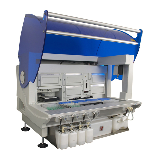
ELISA System 1.1 Overview The DSX™ Automated ELISA System (Figure 1-1) is a computer-controlled microplate analysis system that performs ELISA assays using protocols that are established via an application program and a personal computer. It is intended for use in clinical, research and industrial laboratories and is especially useful for laboratories with medium throughput, multiple assay workloads. -
Page 14: Functional Description And Features
Functional Description and Features 1.2 Functional Description and Features The DSX™ Automated ELISA System is designed to automate each of the steps in an ELISA assay, including sampling, distribution, dilution, addition of reagents, incubation, washing, detection and data processing. All operations are performed via an assay protocol established by the application program;... -
Page 15: Steps In An Analysis
REAGENTS, STANDARDS, DILUENTS, CONTROLS Figure 1-2 Operation Steps of the DSX™ Automated ELISA System 1 Addition of Samples, Reagents, Standards, Diluents and Controls to the Plates The automated pipette is used to withdraw the appropriate amount of sample, reagent, standard, diluent or control from tubes (bottles) that are located in the workspace and add the liquid to the appropriate wells. -
Page 16: Major Components Of The System
A detailed discussion of each component is presented in Chapters 5-17. The DSX™ Automated ELISA System is an integrated system that consists of a number of modular systems that are controlled via the application software. This section describes each major component. -
Page 17: Ambient Drawer And Plate Holders
Position 1 Position 2 Position 3 Position 4 Figure 1-4 Ambient Drawer Gripping Positioning Slot Spring Clips Figure 1-5 Plate Holder DSX™ System Service Manual... -
Page 18: Pipette Module
Pipette Figure 1-6 Pipette Module The pipetting system of the DSX™ Automated ELISA System includes ESP™ (Electronic Signature Pipetting) software for automatic detection of clots, foam, or bubbles when pipetting samples. The pipetting signature observed when pipetting each sample is compared to nominal pipetting signatures of particular sample types (for example, serum or plasma) obtained during system configuration. -
Page 19: Incubator Modules
Processing of the work list will not commence until the temperature of each required incubator module is at the correct value. Incubator Modules Ambient Drawer Figure 1-7 Incubator Modules DSX™ System Service Manual... -
Page 20: Wash Module
Raising the wash head assembly allows the wash head to be moved so another column can be washed or so the wells can be filled. Plate Wash Dispense/Aspirate Drawer Head Pins Figure 1-8 Wash Module DSX™ System Service Manual... -
Page 21: Wash Buffer Containers
Dispense Dispense Valve A Valve B lve C alve D Wash Buffer Wash Buffer Wash Buffer Wash Buffer Container A Container B Container C Container D Figure 1-9 Wash Buffer Containers and Wash Buffer Dispense Valves DSX™ System Service Manual... -
Page 22: Waste Containers
Used sample and reagent pipette tips are disposed into the Tip Waste Container. Both containers are located at the front of the instrument (Figure 1-10). Tip Waste Liquid Waste Container Container Figure 1-10 Waste Containers 1-10 DSX™ System Service Manual... -
Page 23: Absorbance Module
(for example, Blanking, QC Raw Data, Threshold or Curve Fitting) are applied, and the calculated results for the microplate are reported. The location of the absorbance module is shown in Figure 1-11. Absorbance Module Ambient Drawer Figure 1-11 Absorbance Module DSX™ System Service Manual 1-11... -
Page 24: System Cover
To close the cover, push down on the handle until the cover is fully closed and locked. The system cover rests on the front extrusion when it is fully closed. System Cover Front Extrusion Figure 1-12 System Cover 1-12 DSX™ System Service Manual... -
Page 25: Application Software
Application Software 1.5 Application Software The DSX Automated ELISA System is controlled by a personal computer and application software which automates the sample distribution, incubation, reagent addition, washing and detection phases of microplate assays. It also provides the user interface for configuration of the instrument and management of consumables (Figure 1-13). -
Page 26: Contents Of This Manual
This manual contains the following information: Section A: General Service Information • Chapter 2: Installation - describes how the DSX Automated ELISA System is installed in the customer's facility. • Chapter 3: Maintenance and Introduction to Service - Outlines a series of activities that should be performed on a routine basis and describes the general approach to servicing the system. - Page 27 (for example, the EPOD and the back plane board). In addition, a series of appendices are included: a list of tools required to service the system, a copy of the user warranty, specifications, and definitions of warning labels that are on the system. DSX™ System Service Manual 1-15...
- Page 28 Contents of this Manual This page intentionally left blank. 1-16 DSX™ System Service Manual...
-
Page 29: Chapter 2 Installation
2.2 Receipt of the System The DSX™ Automated ELISA System is normally shipped in a single crate and the PC that is to be used with the system is shipped in cartons (normally 3). Upon arrival of the system, the customer should inspect the shipment and ensure that all components have arrived in good shape. -
Page 30: Loading The Application
Loading the Application 2.5 Loading the Application The DSX™ Automated ELISA System can be used with the following operating systems (this information can change with the release of any new version of software so it is best to review the software notes or any bulletins regarding current specifications): •... - Page 31 It is suggested that you place an icon on the desktop for the program. This can be done by using the Search command to find Revelation.exe, right clicking on it and then selecting Create a Shortcut. A dialog box will be presented asking if you want to place a shortcut on the desktop. DSX™ System Service Manual...
-
Page 32: Initializing Communication
The system will present the Revelation welcome screen (Figure 2-1). Figure 2-1 First Screen Select the Connect to DSX (on Port1) radio button and press the Do It button to present the Reader Type dialog box (Figure 2-2). Note: The DSX™ Automated ELISA System should normally be connected to Communication Port 1. - Page 33 Initializing Communication Select DSX and press Setup to present the Setup DSX dialog box (Figure 2-3). Figure 2-3 Setup DSX Dialog Box DSX™ System Service Manual...
- Page 34 Click OK. If the appropriate communication port has been selected and communication between the computer and the DSX has been established, the DSX will go through a self-test and generate a report. A typical self-test report is shown in Figure 2-4.
- Page 35 Initializing Communication If the personal computer cannot establish communication with the system, the DSX Communication Module Error dialog box is presented (Figure 2-5). Figure 2-5 DSX Communication Module Error Dialog Box Press the Recovery Options button to present the options at this point (Figure 2-6). The Manual Control selection lets you manually operate various components of the system and is not used at this point.
-
Page 36: Loading The Desired Assay
Loading the Desired Assay In most cases, the problem is that you have not connected the DSX™ Automated ELISA System to the indicated communications port on the personal computer. If this is the case, select Setup the communications settings option to present the Setup DSX dialog box (Figure 2-7) and select the correct port (at this point, do not worry about the rest of the tabs). -
Page 37: Chapter 3 Maintenance And Introduction To Service
ENSURE THAT THE SYSTEM HAS BEEN DECONTAMINATED OR TAKE SUITABLE PRECAUTIONS (e.g., WEAR RUBBER GLOVES AND SUITABLE EYE PROTECTION). IF THE SYSTEM IS SENT BACK TO A DYNEX TECHNOLOGIES FACILITY, THE USER MUST CERTIFY THAT THE UNIT HAS BEEN DECONTAMINATED. -
Page 38: User Maintenance
5 Purge the washer with 50 mL of deionized water. 6 The Pipette Spigot tip should be cleaned with alcohol at the end of each day. Note: The deionized water used for purging should be placed in Wash Buffer Container D. DSX™ System Service Manual... - Page 39 8 Check Workspace and coordinate calibrations (refer to the section entitled Post-Service Checkout Protocol on page 3-6). 9 Perform verification of the reader using the appropriate verification plate and perform the Tip Alignment test. 10 Perform temperature verification on the incubators using the proper verification plate. DSX™ System Service Manual...
-
Page 40: Cleaning And Decontamination
If dispense or aspiration tips become clogged, use the wires supplied with the system to remove any particulate matter from them. If a system is returned to a DYNEX Technologies facility, the customer must decontaminate the system before shipment and a decontamination certificate must be submitted with the unit (see Cleaning and Decontamination on page 3-4). -
Page 41: Servicing The Dsx Automated Elisa System
The incubator modules, the detector module, the ambient drawer and the washer module are readily removed from the DYNEX Technologies DSX Automated ELISA System. When a problem is identified in one of these modules, the normal service operation is to replace the entire module and return the defective one to a service center. -
Page 42: Post-Service Checkout Protocol
Calibration Jig (Part No. WAFIX-003) onto the workspace at the left-hand end. Make sure that the holes and pins align. The pillars on the plate should be in the back-left and front-left corners of the workspace area on the DSX, as shown in Figure 3-1. - Page 43 Post-Service Checkout Protocol 2 Start Revelation, select “Tools” and then select “Configure System”. Select the Coordinate Calibration tab of the Setup DSX dialog box (Figure 3-2). Figure 3-2 Setup DSX Dialog Box - Coordinate Calibration Tab 3 Press the Calibrate Workspace button to start the Workspace Calibration procedure.
- Page 44 AUTOMATICALLY. TAKE CARE THAT YOUR HANDS, FACE, ETC., ARE NOT IN THE WORKSPACE AREA DURING THIS OPERATION. 6 The program will alert you to move the pipette tip to the front and repeat steps 4 and 5. DSX™ System Service Manual...
- Page 45 Post-Service Checkout Protocol 7 Revelation will move the XYZ arm over to the right-hand end of the DSX to record the position of the right-back pillar. Remove the Calibration Jig and place it as shown in Figure 3-4. Figure 3-4 Positioning the Workspace Fixture - Right Side of DSX Workspace 8 The program will alert you to move the pipette tip to the rear pillar and repeat steps 4 and 5.
-
Page 46: Module Calibration
Module calibration is performed to make sure that the coordinates for each module is properly defined so that the pipette arm can move the plates as appropriate. The present position of each module is indicated in the Module Calibration region of the Setup DSX dialog box - Coordinate Calibration Tab (Figure 3-2). -
Page 47: Drawer Calibration
To Perform the Drawer Calibration: 1 Start Revelation, select Tools and then select Configure System. Select the Coordinate Calibration tab of the Set-up DSX dialog box (Figure 3-2). 2 Select Calibrate Drawer. Follow the on-screen instructions to calibrate the drawer. -
Page 48: Manual Adjustment Of The Module Calibration
1 Start Revelation, select Tools and then select Configure System. Select the Coordinate Calibration tab of the Set-up DSX dialog box (Figure 3-2). 2 Select the module to manually adjust by left clicking on it with the mouse and then select Manual Adjustment. - Page 49 Note: If an error occurs, choose Recovery Options followed by Abort the Operation. The coordinates can then be modified and the attempt repeated. Clamp Body Pick-up Block Pipette Spigot Figure 3-6 Pipette Entering Plate Holder Assembly Prior to Clamping DSX™ System Service Manual DSX™ System Service Manual 3-13 3-13...
- Page 50 When finished, click OK to save the values. If you make any changes and exit without selecting OK, the values will not be saved. Plate Carrier Plate Holder Alignment Vees Figure 3-7 Plate Alignment Vees 3-14 DSX™ System Service Manual...
-
Page 51: Cycle Test
Drawer Calibration on page 3-11. 3.5.8 Tip Alignment Test Perform the Tip Alignment test described in the section entitled Manual Control Operations on page 5-2. DSX™ System Service Manual 3-15... -
Page 52: Manual Wash Plate Test
3 Select the fluid to load, the volume and select OK. The program will show the location to load the washer fluid; select the green check mark when complete. The program will return to the DSX Manual Control dialog box. 4 The Washer should still be highlighted in the left column, select wash a plate from the right column and select Do It. - Page 53 Insert a carrier with the appropriate plate and select OK. 6 The unit will perform the operation. Note: This is a basic example of a simple wash; it can be tailored to operate differently depending on the desired outcome. DSX™ System Service Manual 3-17...
-
Page 54: Returning Components
Returning Components 3.6 Returning Components When a component (for example, a washer) is to be returned to DYNEX Technologies, the user or service engineer is expected to obtain a return authorization number before shipping the unit and must include an Equipment in Transit form (Figure 3-10). For international locations, please contact your local DYNEX Technologies facility. -
Page 55: Chapter 4 Troubleshooting
Overview Chapter 4 Troubleshooting 4.1 Overview Although the DSX Automated ELISA System consists of several components, troubleshooting can be simplified by a consideration of the following guidelines: • In almost all cases there is a single proximate cause for a problem. -
Page 56: Initialization
The fuse is blown Replace fuse on the side of the main assembly. The breaker on Reset the breaker. the mains power line is tripped The power supply Replace the power supply in the EPOD. is defective DSX™ System Service Manual... -
Page 57: The System Cannot Communicate With The Computer
Com Port 1). See Checking the Communication Link on page 4-4. Hardware Link Hardware not Check communication setting and cables. present Password Wrong password Enter correct password (See Incorrect Password Error on page 4-5). DSX™ System Service Manual... -
Page 58: Checking The Communication Link
Initialization 4.2.4 Checking the Communication Link If the communication cannot be established, the DSX Communication Module Error: System is not responding dialog box is presented (Figure 4-1). Figure 4-1 DSX Communication Module Error Dialog Box Press the Recovery Options button to present the options that are available at this point (Figure 4-2). -
Page 59: Incorrect Password
(Figure 4-3), which is used to select the desired communications port. In most cases, the problem is that you have not connected the DSX™ Automated ELISA System to the indicated communications port on the personal computer. If this is the problem, select the correct port (at this point, do not worry about the rest of the tabs). -
Page 60: System Problems
The command was Check the communication settings and Device already/not open. not accepted by the cables. module Directory nnn Program could not Make sure the drive and directory are correct. does not exist. find the specified directory DSX™ System Service Manual... - Page 61 Setup program again. If Microsoft Office is Failure. use a file that was running, remove its icon from the Startup being used by another group and reload Windows. You can replace Windows program. Office in the Startup group once Revelation is loaded. DSX™ System Service Manual...
- Page 62 PC. OLE 2.0 A fault has occurred in Try repeating the command or reboot the Initialization the program program failed. Unable to Check the communication settings and allocate queues. cables DSX™ System Service Manual...
-
Page 63: Problems In A Specific Module
The service engineer can perform a wide variety of operations (such as ejecting a plate from the reader module) via the DSX Manual Control feature, which is described in Chapter 5). In addition, a large number of primary functions (for example, advancing the plate motor one step) can be performed via the advanced manual control feature, described in section entitled, Manual Control Operations on page 5-2. -
Page 64: Application Problems
Application Problems Application Problems Two general types of problems may be noted with the DSX Automated ELISA System: • Hardware/Software Problem: When a hardware or software fault is noted, the service engineer is expected to repair, replace, or remedy the problem as described in this manual. -
Page 65: Chapter 5 Manual Operation Of The System
To access the manual mode of operation, press DSX Manual Control… on the Tools menu. As an alternative, the manual mode of operation can be accessed if the system is not properly initialized (see the Overview in Chapter 2 on page 2-1). -
Page 66: Manual Control Operations
5.2 Manual Control Operations 5.2.1 Selecting the Desired Operation When Manual Control is selected, the DSX Manual Control dialog box (Figure 5-1) will be presented. The left column indicates the devices that can be tested and the right column indicates the operation that can be tested for the selected device. To select a different device, move the highlight in the left column to the appropriate entry, to perform a different operation for the selected device, move the highlight in the right column to the desired operation. -
Page 67: Performing The Operation
This dialog box is used to indicate the direction of movement and the distance that the arm is to be moved (Figure 5-2). Figure 5-2 DSX Manual Arm Movement Dialog Box 5.2.3 Testing the Reader The Reader test selections are listed in the right column of Figure 5-1. The self-test operation incorporates all of the individual operations. -
Page 68: Testing The Drawer
The Drawer test selections are listed in the right column of Figure 5-3. The self-test operation incorporates all of the individual operations. Figure 5-3 DSX Manual Control Dialog Box (Drawer Selections) When you click on the Do It button, the status line will indicate that the system is performing the operation (for example, Doing a Drawer Out Operation). -
Page 69: Incubators
The Incubator test selections are listed in the right column of Figure 5-4. The self-test operation incorporates all of the individual operations. Figure 5-4 DSX Manual Control Dialog Box (Incubator Selections) When you click on the Do It button, the Status line will indicate that the system is performing the operation (for example, Doing a Move to Front Home operation). -
Page 70: Washer
The Washer test selections are listed in the right column of Figure 5-5. The self-test operation incorporates all of the individual operations. Figure 5-5 DSX Manual Control Dialog Box (Washer Selections) For the Eject the washer plate carrier, Retract the washer plate carrier, Raise the washer head... - Page 71 (Figure 5-8), which is used to indicate the desired operations is presented. A detailed discussion of this operation is presented in the section entitled, Washing A Plate on page 5-13. Figure 5-8 Wash Plate Dialog Box DSX™ System Service Manual...
-
Page 72: Plate Movement
The Plate Movement test selections are listed in the right column of Figure 5-9. Figure 5-9 DSX Manual Control Dialog Box (Plate Movement Selections) When you click on the Do It button, the Status line will indicate that the system is performing the operation (for example, Doing a Plate Movement Putting Plate in Reader operation). -
Page 73: Arm
5.2.8 Arm The Arm test selections are listed in the right column of Figure 5-10. Figure 5-10 DSX Manual Control Dialog Box (Arm Selections) For Lock plate, Unlock plate, Lock cover, Unlock cover, Dispose of tip, Self test the XY,... - Page 74 For the Get Coordinates entry, the status line will indicate that the system is performing the operation. At the completion of the operation, the status line will indicate that the operation is complete. The dialog box will include the coordinates as shown below: Coordinates are 3362, 44, 0 5-10 DSX™ System Service Manual...
-
Page 75: Advanced
When Advanced is selected, the Send command(s) operation is presented (Figure 5-12). Figure 5-12 DSX Manual Control Dialog Box (Advanced Selection) When you press the Do It button, the Command Direct dialog box (Figure 5-13) is presented. -
Page 76: Testing
Testing The Testing test selections are listed in the right column of Figure 5-14. Figure 5-14 DSX Manual Control Dialog Box (Testing Selection) Plate Movement presents a dialog box to prompt the engineer to indicate how many cycles are desired. When the cycle number is indicated, the engineer is prompted to place a plate in the left front drawer position. -
Page 77: Washing A Plate
When the Wash a Plate selection is made on the Washer activity list (Figure 5-5), the Wash Plate… dialog box (Figure 5-17) is presented to indicate the conditions for the test. Figure 5-17 Wash Plate… Dialog Box DSX™ System Service Manual 5-13... - Page 78 A typical wash plate sequence is presented in Figure 5-20. Figure 5-20 Typical Wash Plate Sequence After the entries have been established, click OK to execute the operation. The status line will indicate that operation is proceeding and will indicate when it is finished. 5-14 DSX™ System Service Manual...
-
Page 79: Chapter 6 The Pipette Module/Xyz Drive
As an alternative, the service engineer can use the DSX Manual Control command on the Tools menu to manually perform the desired operations (instead of running an assay.) as described in Chapter 5. - Page 80 The X-Drive and Y-Drive components are discussed in the section entitled The X-Drive and Y-Drive on page 6-3, while the Z-Drive and the Pipette Module are discussed in the section entitled The Z-Drive and the Pipette Module on page 6-11. DSX™ System Service Manual...
-
Page 81: The X-Drive And Y-Drive
An encoder/counter is associated with each motor to ensure correct positioning and an optical sensor is mounted on the rail as a reference. Figure 6-1 Circuit Board Diagram – Board Breakdown DSX™ System Service Manual... - Page 82 The X-Drive and Y-Drive Figure 6-2 XY Control Diagram DSX™ System Service Manual...
- Page 83 The X-Drive and Y-Drive Figure 6-3 X Motor Drive Transition DSX™ System Service Manual...
- Page 84 3 The X encoder and X home sensor are both at the left-hand end of the X track. 4 The Y-Drive board, the Y motor, the Y home sensor and the Y encoder are all grouped together and are located at the end of the Y arm above the X track. DSX™ System Service Manual...
-
Page 85: Command Types
Data commands cause the XY program write and/or read the state of internal variables such as the value of the home offsets, and external variables such as the value of the encoders. A data flow diagram is presented in Figure 6-5. Figure 6-5 Data Flow Diagram DSX™ System Service Manual... -
Page 86: Top Level Functional Design
Y-Drive. On detecting an incoming command, the program decodes it, executes it and replies with the result. Start Initialise Incoming Transmission? Extract Command Handler Exists? Repeat Execute Command Prepare Reply Send Reply Correct Motor Positions At Idle Figure 6-6 Top-Level Functional Design XY Program DSX™ System Service Manual... -
Page 87: Hardware Considerations
Logic and Control supplies - The +12 V from the module interface is used directly for the flash programming voltage (FVPP), it is also the input to a dc\dc converter which provides the 5 V logic supply. The logic GND is star connected to chassis on the Back Plane. DSX™ System Service Manual... - Page 88 RS-232 interface. Interface drivers and receivers are used between the COM1 serial communications channel on the H8 microprocessor and the interface connector to provide proper RS-232 signal levels to the controller. DSR is signalled via Port 8-6. 6-10 DSX™ System Service Manual...
-
Page 89: The Z-Drive And The Pipette Module
The Z/Pipette module controls the movement of the Z motor, the Pipette motor and the Eject motor, either individually or together. The electronics of the Z/Pipette module is presented in Figure 6-7 and Figure 6-8. Figure 6-7 Circuit Board Mechanism DSX™ System Service Manual 6-11... - Page 90 The Z-Drive and the Pipette Module Figure 6-8 XY Control Diagram Components of the Z Pipette module are located in different parts of the DSX, as follows: • The Z Pipette main board is in the Z module, which is moved up and down the Z arm.
-
Page 91: Command Types
Data commands cause the Z/Pipette program to write and/or read the state of internal variables such as the value of the home offsets, and external variables such as the value of the Z encoder. The Data Flow diagram is presented in Figure 6-9. Figure 6-9 Data Flow Diagram DSX™ System Service Manual 6-13... - Page 92 Z component moves down to position the plate in the carrier holder. The Eject component moves up so as to disengage the plate carrier, thus loading the plate carrier into the new position. The XY arms then move the Z Pipette module away without the plate. 6-14 DSX™ System Service Manual...
-
Page 93: Top Level Functional Design
Z Transition board on the Z-axis arm. The motor voltage is 24V and the H drivers use current limiting to produce a driving current of 1.5A with boost and 0.9 Amps without boost. DSX™ System Service Manual 6-15... -
Page 94: Serial Communication With The Controller
RS-232 interface. Interface drivers and receivers are used between the COM1 serial communications channel on the H8 and the interface connector to provide proper RS-232 signal levels to the controller. DTR is signalled via Port 8-7 6-16 DSX™ System Service Manual... -
Page 95: Chapter 7 Replacing Components - Pipette/Xyz Axis Assemblies
After the component is reinstalled, it is necessary to perform the post-service checkout protocol as described in the Post-Service Checkout Protocol section on page 3-6. DSX™ System Service Manual... -
Page 96: Troubleshooting
Replace Optointerrupter (refer to the Defective Removing the Y Optointerrupter section). Y Encoder Defective Replace Encoder (refer to the Replacing the Encoder section). Y Pulley Misaligned Align one or both pulleys (refer to page 7-50 for the procedure). DSX™ System Service Manual... - Page 97 Defective Pipette Replace the Pipette Assembly (refer to page Pipette does not pick up or Assembly 7-4 for the procedure) deposit pipette Defective Z-Drive See Z Drive Not Functioning or does not tips travel correct distance above. DSX™ System Service Manual...
-
Page 98: Replacing The Pipette Assembly
BHCS screws and five M3 shakeproof washers (Figure 7-1). (For clarity, the Z-Arm and Y-Arm covers are shown removed) Figure 7-1 Removing the Pipette Cover Note: When replacing the cover, make certain that the cover is flush with respect to the mount. DSX™ System Service Manual... - Page 99 Replacing the Pipette Assembly 2 Remove the Cable from the Pipette Controller Board (Figure 7-2). Controller Board Hole Figure 7-2 Unplugging the Cable from the Controller Board DSX™ System Service Manual...
- Page 100 M3 x 12 SHCS screws that attach the Pipette Assembly to the Drive Assembly (Figure 7-3). The block is pinned in the center, so rocking the pipette from left to right will frequently aid in removing the module from the Z mount. Figure 7-3 Mounted Pipette Assembly DSX™ System Service Manual...
- Page 101 4 Ensure that the pipette bottom plane is parallel to the fixture. If it is not parallel to the Y-plane, readjust as noted in Steps 1 through 3. If it is not parallel to the X-plane, readjust as noted on page 7-15. DSX™ System Service Manual...
- Page 102 1 Remove the Z-Axis Top Cover (Part No. 204018000) from the Z-Axis Drive Assembly by removing the three M3 x 6 Button Head screws and three shakeproof washers (Figure 7-5). Figure 7-5 Z-Axis Drive Assembly: Top Cover DSX™ System Service Manual...
- Page 103 2 Remove the Z-Axis Lower Cover (Part No. 204005100) by removing the three M3 x 6 Button Head screws and shakeproof washer. There are two screws on the bottom and one on the side with a shakeproof washer (Figure 7-6). Figure 7-6 Z-Axis Drive Assembly: Bottom Cover DSX™ System Service Manual...
- Page 104 M3 x 6 Button Head screws and two M3 shakeproof washers that attach the cover to the Drive Assembly and unsnapping it from the body (Figure 7-7). Figure 7-7 Removing the Z-Axis Drive Assembly Mid Cover 7-10 DSX™ System Service Manual...
- Page 105 Replacing the Pipette Assembly 4 Remove the Z-Drive Spring Cover (Part No. 22001010) by removing the two M3 BHCS screws that secure the cover to the extrusion (Figure 7-8). Spring Cover Figure 7-8 Removing the Spring Cover DSX™ System Service Manual 7-11...
- Page 106 5 Remove the Pipette Cover (Part No. 204010400) by removing the five M3 x 6 BHCS screws and five M3 shakeproof washers (Figure 7-9). Figure 7-9 Removing the Pipette Cover Note: When replacing the cover, make certain that the cover is flush with respect to the mount. 7-12 DSX™ System Service Manual...
- Page 107 Replacing the Pipette Assembly 6 Remove the Cable from the Pipette Controller Board (Figure 7-10). Controller Board Hole Figure 7-10 Unplugging the Cable from the Controller Board DSX™ System Service Manual 7-13...
- Page 108 (Figure 7-11). The block is pinned, so rocking the pipette from left to right will frequently aid in removing the module from the Z mount. 8 Remove the Z flex cable plate. Z Flex Cable Plate Figure 7-11 Mounted Pipette Assembly 7-14 DSX™ System Service Manual...
- Page 109 6 Release the clamp, and ensure that the pipette bottom plate is parallel to the fixture. If the pipette bottom plate is not parallel to the fixture, readjust as outlined above. Remove the fixture from the system. DSX™ System Service Manual 7-15...
-
Page 110: The Z-Drive Assembly
Note: When the Z-Drive Assembly is reattached to the Y-Drive Assembly, make certain that the Z-Drive Assembly is held tightly against the datum edge (Figure 7-13). After the screws are tightened, secure them with Loctite 222. 7-16 DSX™ System Service Manual... -
Page 111: Replacing The Z-Drive Spring Assembly
2 Remove the 4 M 3 x 30 flat head screws that attach the cover to the mechanism (Figure 7-14). Figure 7-14 Removing Housing Cover Screws Note: When reassembling the Spring Assembly housing, rotate the cover eight times counter-clockwise before attaching the screws. DSX™ System Service Manual 7-17... - Page 112 Note: When reinstalling the spring assembly, make sure that the eye lines up with the groove in the shaft and take care to ensure that the spring remains inside the housing. 7-18 DSX™ System Service Manual...
- Page 113 M3x30 flat head screws. Note: Ensure that the assembly is square and flush with the extrusion and that the two tapped holes in the housing are on the bottom when completed. Figure 7-17 Insertion of Rotary Spring DSX™ System Service Manual 7-19...
-
Page 114: Removing And Replacing The Z-Drive Encoder
In Figure 7-18, the cover is shown in the open position, and the cover should be rotated approximately 15 degrees counter clockwise (the position is indicated by the correspondence of the dot on the notch and the dot on the housing). 7-20 DSX™ System Service Manual... -
Page 115: Replacing The Z-Drive Optointerrupter Assembly
To remove the sensor assembly, remove the two M3X6 Cap Head Screws and 2 M3 Shakeproof washers. When you replace the assembly, ensure that the Z sensor Flag passes through the middle of the sensor. Figure 7-20 Z-Axis Sensor Plate DSX™ System Service Manual 7-21... -
Page 116: Replacing The Z-Drive Belt
2 Remove the Blocks that are attached to each end of the belt from the Linear Bearing Block. Figure 7-21 Removing the Z-Drive Block Breaker Flag Figure 7-22 Location of the Z Sensor Breaker Flag 7-22 DSX™ System Service Manual... - Page 117 204012400) to the motor end of the belt using two M3 x 8 Cap Head Screws and Loctite 222 (Figure 7-24). Ensure that the belt covers all three teeth in the belt block. Figure 7-24 Placing the Fixed Belt Block on the Motor End of the Drive Belt DSX™ System Service Manual 7-23...
- Page 118 Z-Drive block (Part No. 204004600) onto the linear bearing block (Figure 7-26). Fit the Z-Drive Block to the Linear Bearing Block using the four M3 x 6 Cap Head screws. Figure 7-26 Z-Drive Block and the Linear Bearing Block 7-24 DSX™ System Service Manual...
- Page 119 6 Mount the adjustable Belt Block in the slotted holes using two M3 x 12 cap head screws and two M3 flat washers but do not tighten. Insert one M3 x 30 button Posi head screw through the adjustable belt block and into the fixed belt block. DSX™ System Service Manual 7-25...
- Page 120 Individually remove and re-install each screw in the adjustable block, including the long adjustment screw, applying Loctite 222 to each screw and then tightening. Figure 7-28 Location of Positioning Jig 7-26 DSX™ System Service Manual...
-
Page 121: Replacing The Z Motor
2.2 mm. 3 When reattaching the motor, use Loctite 222 on the screws and ensure that the wires are facing the Idler Assembly. Figure 7-30 Affixing the Pulley to the Motor DSX™ System Service Manual 7-27... -
Page 122: Replacing The Idler Assembly
1 Remove the bearing plate (Part No. 20400440) by removing the 2 flat head screws (Figure 7-31). Figure 7-31 Bearing Plate Cover 2 Remove the pulley from the shaft by removing the M4 x 6 cone Point Set Screw (Figure 7-32). Figure 7-32 Pulley Assembly 7-28 DSX™ System Service Manual... - Page 123 Secure the pulley to the shaft using one M4 x 6 Cone Point Set Screw (Part No. 307400406) and Loctite 222 (discard the supplied setscrew). Ensure that there is no play in the mechanism. DSX™ System Service Manual 7-29...
-
Page 124: Replacing The Z Axis Transition Board
(Figure 7-34). Figure 7-34 Location of Standoffs/Z Transition Board Note: When replacing the board, make certain that the insulation pads (Part No. 344001201) are placed between the Drive IC blocks and the flexi cable cover. 7-30 DSX™ System Service Manual... -
Page 125: The Y-Drive Assembly
Note: Apply Loctite 222 to the screw before tightening them. Be sure to hold the Y-Drive Assembly tight against the datum edge when reassembling. Otherwise there may not be sufficient travel along the Y-axis, causing problems when the seventh rack is handled. DSX™ System Service Manual 7-31... -
Page 126: Removing The Y-Transition Printed Circuit Board
IC plates and the Y extrusion and secure the IC mounting plates to the extrusion and assemble in reverse order. Note: The cover for the EMC box should be added after the Y-axis is mounted on the system. 7-32 DSX™ System Service Manual... -
Page 127: Replacing The Encoder
The encoder is mounted on top of the Y motor as shown in Figure 7-37. Figure 7-37 Y Encoder To remove the encoder, release the Allen screw that holds the assembly to the motor shaft. When the screw is released, the cover will be easily removed. DSX™ System Service Manual 7-33... - Page 128 Figure 7-38 Mounting the Y-Encoder After you have mounted the encoder, tighten the Allen screw, then rotate the encode cover from the open to the closed position (Figure 7-39). Figure 7-39 Positioning the Y-Axis Encoder 7-34 DSX™ System Service Manual...
-
Page 129: Removing The Y-Axis Drive Belt
2 Remove the Y-flexicable Run bracket (Part No. 204003800) from the Y-Drive Axis (Figure 7-41) by removing the 3 M3 x 6 caphead screws (when this is replaced, secure the screws with Loctite 222). Figure 7-41 Flexicable Run Bracket DSX™ System Service Manual 7-35... - Page 130 Figure 7-42 Removing the Sensor Flag and Belt Blocks 4 Remove the Y-Drive block from the linear bearing block by removing the four M3 x 6mm cap head screws (Figure 7-43). Figure 7-43 Removing Y-Drive Block 7-36 DSX™ System Service Manual...
- Page 131 On the motor end of the belt install the Y-belt fixed block (Part No. 204010500) using one clamp block (Part No. 204012400) and two M3 x 8 cap head screws. After the blocks are prepared, use Loctite 222 to secure the screws. Figure 7-44 Y Belt Assembly DSX™ System Service Manual 7-37...
- Page 132 M3 x 6mm-cap head screws and Loctite 222 (Figure 7-45). Ensure the Y- Drive block lip is flush with the linear slide as well as the side facing the motor. Figure 7-45 Y-Drive Block Design 7-38 DSX™ System Service Manual...
- Page 133 M3 x 12 cap head screws and two M3 flat washers, do not tighten. Insert one M3 X 30 button Posi head screw through the adjustable belt block and into the fixed belt block. Figure 7-46 Y-Drive Cable Bracket Closed DSX™ System Service Manual 7-39...
-
Page 134: Removing The Y Optointerrupter
The Y Optointerrupter is mounted as shown in Figure 7-47. To remove the Y sensor, remove the two screws. When you replace the sensor, make certain that the Y-Flag travels through the center of the sensor. 7-40 DSX™ System Service Manual... -
Page 135: Removing The Pulley
The Y Axis motor (Part No. 528301000) is attached to the Y-Axis extrusion via two M3 x 8 mm cap head screws and two M3 x 10 mm cap head screws as shown in Figure 7-49. Figure 7-49 Mounting the Y Axis Motor DSX™ System Service Manual 7-41... -
Page 136: Replacing The Idler Pulley
The Idler Pulley is made from two flanged bearings (Part No. 322000801) as shown in Figure 7-50. To remove the bearing, unscrew the M3 x 6 cap head screw and flat washer. When replacing the bearings, use Loctite 222 and secure the screw. Figure 7-50 Replacing the Idler Pulley 7-42 DSX™ System Service Manual... -
Page 137: The X Axis Drive Assembly
To remove the X-Axis motor (Figure 7-52), remove the three M4 x 16 SKT cap screws that attach the motor to the motor mount. When replacing the motor, secure the screws using Loctite 222. Figure 7-52 Location of X-Axis Motor DSX™ System Service Manual 7-43... -
Page 138: Replacing The Encoder
Figure 7-53 X-Drive Encoder To Reinstall the Encoder 1 Place the encoder on top of the encoder mounting plate as shown in Figure 7-54. It will snap into place. Figure 7-54 Mounting the X-Encoder 7-44 DSX™ System Service Manual... - Page 139 3 Rotate encoder cover from the open to closed position by inserting a small flat blade screwdriver into the notch and rotating. The encoder cover is shown in the closed position in Figure 7-55. Figure 7-55 X-Encoder Position DSX™ System Service Manual 7-45...
-
Page 140: Removing The Pulley From The X-Drive Motor
If the jig is not available, use a micrometer to set the distance from the bottom of the pulley to the top of the motor housing to 2.2 mm. The screws supplied with the pulley should be discarded, use M4 x 6 cone point set screws (Part No. 307400406) instead. 7-46 DSX™ System Service Manual... -
Page 141: Replacing The X Idler Pulley Assembly
M1.6 x 6 posi pan screws. 3 Remove the Bearing Boss (Part No. 2040003100) by removing the 3 M4 x 16 skt cap screws (Figure 7-58). 4 Remove the pulley assembly from the main plate. Figure 7-58 Bearing Boss X-Pulley DSX™ System Service Manual 7-47... - Page 142 X Plate. Figure 7-60 Positioning the Alignment Fixture Around the Pulley Assembly 7-48 DSX™ System Service Manual...
- Page 143 Encoder Mounting Jig (DSXFIX015) and three M1.6X6 Pan Head Screws (303800106). Note: Ensure that the mounting plate is centralized around the pulley idler shaft. 6 Continue by mounting the encoder (see Replacing the Encoder on page 7-44). DSX™ System Service Manual 7-49...
-
Page 144: Adjusting The X-, Y-, Or Z- Motor Pulley And Idler Pulley
Drive Motor Pulley to the shaft, slide the pulley 2 mm away from the edge of the belt, and retighten the two screws. 3 Perform an Arm self test by selecting DSX Manual Control from the Tools menu, responding Yes to the prompt, and then selecting Arm in the left panel and Self- Test the XY or Self-Test the Z (as appropriate) in the right panel. -
Page 145: Replacing The X Transition Printed Circuit Board
7.6.7 Replacing the X Transition Printed Circuit Board The X Transition Printed Circuit Board is mounted on the left side of the system as shown in Figure 7-61. Figure 7-61 Location of X-Transition Printed Circuit Board DSX™ System Service Manual 7-51... - Page 146 3 Secure the heat sink on the underside of the X-Transition PCB to the right frame panel using two M3X6 Cap Screws and washers. 4 Tighten the four M3 Nylock nuts and four M3 Nylon washers that secure the X-Transition PCB to the tray. 7-52 DSX™ System Service Manual...
-
Page 147: Replacing The X-Drive Belt
1 Loosen (by one-half turn only) the four screws that secure the adjustable block to the X carriage (Figure 7-62). Figure 7-62 X-Drive Belt Adjustment Block 2 Remove the adjustment screw completely. 3 Loosen the adjustable block and the fixed block enough to free the ends of the belt. DSX™ System Service Manual 7-53... - Page 148 Use 4 M3 x 12 skt cap screws; apply Loctite 222 and secure the screws. Note: The threaded hole must face to the left. Figure 7-63 Mounting the Fixed Block 7-54 DSX™ System Service Manual...
- Page 149 Figure 7-64 Mounting the Adjustable Block 3 Fit the adjustment screw (Part No. 303000335) through the adjustable block and into the fixed block (Figure 7-64). 4 Tighten the X Belt according to the following procedure. DSX™ System Service Manual 7-55...
- Page 150 Then repeat the above steps to record ten new readings and calculate the average. 8 Tighten the four screws in the adjustable block. Then double-check the belt tension. 7-56 DSX™ System Service Manual...
-
Page 151: Spare Parts And Jigs
Idler Pulley 23001650 M4 x 6 Cone Point Set Screw 30700406 Z-Axis Transition Board 582050402 IC Mounting Plates 204026600 Insulation Pads 344001201 Pipette Assembly 13001450 Linear Bearing, 12 x 320 mm 322002000 Z Flexi Cable 15001030 DSX™ System Service Manual 7-57... -
Page 152: Y-Drive Assembly (13001430)
Y-Belt Adjustable Belt Block 204010600 Y-Drive Block 204003200 Y-Clamp Block 204012400 Y-Sensor 15001160 Y-Sensor Breaker Flag 204003600 Y-Sensor Plate 204003000 Y-Axis Pulley 320101000 Y-Motor 528301000 Idler Shaft 204002900 IC Mounting Plates 204031400 Idler Pulley Bearings (2) 322000801 7-58 DSX™ System Service Manual... -
Page 153: X-Drive Assembly (13001420)
Part Number X-Motor Pulley Height Setting Jig XMFIX010 X-Belt Tensioning Jig Brecoflex Meter Y-Motor Pulley Height Setting Jig YMFIX010 Y-Belt Tensioning Jig YMFIX012 Z-Motor Pulley Height Setting Jig ZMFIX010 Z-Belt Tensioning Jig ZMFIX012 Encoder Jig DSXFIX015 DSX™ System Service Manual 7-59... - Page 154 Spare Parts and Jigs This page intentionally left blank. 7-60 DSX™ System Service Manual...
-
Page 155: Chapter 8 The Incubator Module
The period of time and the temperature setting is established in the application program for the specific assay for which the DSX Automated ELISA System is employed. -
Page 156: Electrical/Control Considerations
Revelation application program. A circuit block diagram of the Incubator Module is presented in Figure 8-1. Figure 8-1 Circuit Block Diagram - Incubator Module DSX™ System Service Manual... - Page 157 PWM0 and PWM1 outputs of the microprocessor. The PWM0 and PWM1 outputs are connected to power transistors that directly drive the two heaters. The duty cycle of the PWM’s are varied to control the amount of heat generated by the heaters. DSX™ System Service Manual...
-
Page 158: Operational Activities For The Incubator Module
2 The well plate is removed from the plate carrier by the pipette tip. 3 The plate carrier is drawn back into the module. The movement of the plate carrier is terminated when the sensor determines that the plate carrier is driven to the full internal position. DSX™ System Service Manual... -
Page 159: Chapter 9 Servicing The Incubator Module
There is a fault on the IM Module Main board. Plate carrier Plate front sensor is Replace faulty sensor. faulty. drives fully into the IM Module. Replace IM Module Main board is faulty. IM Module Main board is faulty. DSX™ System Service Manual... - Page 160 Bezel opening. Plate carrier Belt bracket not Loosen and then reposition the belt bracket. moves but does positioned properly not eject near the (hitting rear pulley). back. DSX™ System Service Manual...
-
Page 161: Removing External Components
9.3.1 The Top Cover The top cover (Part No. 22000800) is removed by loosening the 3 M3 x 6mm BHCP screws and then lifting the top cover off (Figure 9-1). Figure 9-1 Removing the Top Cover DSX™ System Service Manual... -
Page 162: The Bottom Cover
9.3.2 The Bottom Cover The bottom cover (Part No. 22000780) can be removed by removing the 3 M3 x 6mm button head screws and then lifting the bottom cover off (Figure 9-2). Figure 9-2 Removing the Bottom Cover DSX™ System Service Manual... -
Page 163: The Front Bezel
Figure 9-3 Removing the Front Bezel To reattach the bezel to the chassis, use 4 M3 x 8mm socket head cap screws and M3 washers. Insure that the flat washer is against the bezel, not the lock washer. DSX™ System Service Manual... -
Page 164: Removal/Replacement Of The Plate Carrier Door
1 Insert a long punch through the side of the bezel and push the pin through the door hinge (Figure 9-4). One of two bezel holes for punch insertion Figure 9-4 Bezel Holes for Hinge Pin Removal DSX™ System Service Manual... - Page 165 3 To reassemble the door, partially insert 2 M3 x 32mm spring pins into the door. Then insert the 2 torsion springs into the hinge recess with its L-shaped leg in the spring hole and engage the pins to hold the springs (Figure 9-6). Figure 9-6 Reinstalling the Door DSX™ System Service Manual...
- Page 166 Test the door by opening it and then letting go 5 times. The door should shut by itself. If it does not shut properly, use a 3mm Allen wrench to push out the pins and begin the installation procedure again. DSX™ System Service Manual...
-
Page 167: Repairing/Replacing Internal Components
9.4.1 Removal/Replacement of the Main Circuit Board The Main Circuit Board (Part No. 14000300) is mounted on the bottom of the base (Figure 9-8). Figure 9-8 Mounting the Main Circuit Board DSX™ System Service Manual... - Page 168 3 Lift the board off of the standoffs. To Install the Main Board: 1 Installation is the reverse of the removal procedure. 2 After installation, the module must be tested and calibrated using DynexTest software and a calibrated thermometer. 9-10 DSX™ System Service Manual...
-
Page 169: Replacing The Top Heater Plate Assembly
6511300065 M3x6 SHCP, 4X Figure 9-9 Top Heater Plate Assembly Remove the Top heater plate assembly by unscrewing the 4 M3 x 6mm socket head cap screws as shown in Figure 9-9. DSX™ System Service Manual 9-11... - Page 170 2 Attach the heater plate assembly to the heater mounting plate (Part No. 22000920) as shown in Figure 9-11. 3 Place the assembly in position and tighten the screws (Figure 9-9). Figure 9-11 Mounting Heat Plate Assembly to Heater Mounting Plate 9-12 DSX™ System Service Manual...
-
Page 171: Removal Of The Eject Sensor
Note: When re-installing the cable, route it through the cut-out as shown. Ensure that cable from eject sensor lies flat on chassis to prevent interference with plate carrier movement. Note: After replacement, the eject sensor requires calibration using DynexTest software. DSX™ System Service Manual 9-13... -
Page 172: Removing The Position Sensor
The position sensor (Part No. 15000430) is mounted on the base as shown in Figure 9-13 and is removed by unscrewing the two M3 x 6mm Socket Cap screws and lock washers. Figure 9-13 Position Sensor 9-14 DSX™ System Service Manual... -
Page 173: Removal/Replacement Of The Drive Belt
Figure 9-14 Incubator Drive Belt To remove the drive belt, loosen the 3 M3 x 6 mm Button Head Screws that attach the belt mount to the plate carrier assembly (Figure 9-15). Figure 9-15 Belt Mount DSX™ System Service Manual 9-15... - Page 174 4 Wrap the belt around the middle idler, around the back idler, and around the front idler (Figure 9-14), then loop it around the motor assembly. Pull motor to right until tight and tighten the screws. 9-16 DSX™ System Service Manual...
-
Page 175: Removing The Plate Carrier Motor
2 Remove the Motor bracket from the chassis (Figure 9-18). 3 Remove the pulley assembly from motor shaft by loosening the set screw (Figure 9-14 Figure 9-17 Drive Pulley Mechanism DSX™ System Service Manual 9-17... - Page 176 Route the wire from the motor to the right in the back. Apply 7 in-lbs of torque to tighten the screws. Note: When tightening the screws, use torque driver SN160 to tighten the screws to 7 in-lbs. 9-18 DSX™ System Service Manual...
-
Page 177: Removal/Replacement Of The Plate Carrier Assembly
Repairing/Replacing Internal Components 9.4.7 Removal/Replacement of the Plate Carrier Assembly The Plate Carrier Assembly is mounted in the module as shown in Figure 9-19. Figure 9-19 Mounting of the Plate Carrier Assembly DSX™ System Service Manual 9-19... - Page 178 12mm Flathead screws from the bottom of the module chassis. 2 Lift and remove the Plate Carrier from the module chassis. 3 Remove the bearing shaft as shown in Figure 9-20. Figure 9-20 Plate Carrier Assembly 9-20 DSX™ System Service Manual...
-
Page 179: Replacement Of Lower Heater Assembly
Figure 9-22. Figure 9-22 Attaching Heater Foil to Heater Plate Note: Remove all adhesive from the plate carrier. If you are reusing the heater plate, make sure that all old adhesive is removed from the plate. DSX™ System Service Manual 9-21... - Page 180 Note: The cable should be flat, with minimal slack between the heater and the heater clamps. If reusing the original clamps, ensure the sharp edges are facing away from the heater cable. Figure 9-24 Plate Carrier/Heater 9-22 DSX™ System Service Manual...
-
Page 181: Removal/Replacement Of Locking Lever/Pivot/Spring
Repairing/Replacing Internal Components 9.4.9 Removal/Replacement of Locking Lever/Pivot/Spring The plate is held in place by the Locking Lever/Pivot/Spring mechanism shown in Figure 9-25. Figure 9-25 Locking Lever/Pivot and Spring DSX™ System Service Manual 9-23... - Page 182 3 If it is necessary to remove the pivot and/or locking lever, use a small flat screwdriver. Note: When replacing the spring, take care that the spring is not over- stretched. 9-24 DSX™ System Service Manual...
-
Page 183: Removal/Replacement Of The Plate Carrier Bearings
(note diagram) and lock in place using one M3 fender washer, one M3 x 6mm socket head cap screw and one M3 lock washer. DSX™ System Service Manual 9-25... -
Page 184: Spare Parts
Upper Gravity Block 23001370 Lower Gravity Block 23001220 23001260 Eject Sensor 15000580 Plate Presence LED Assembly 15000590 LED Holder 50200480 Incubator Printed Circuit Board 14000300 9.6 Jigs Description Part Number Heater Foil Jig IMFIX001 Pulley Gauge AMFIX002 9-26 DSX™ System Service Manual... -
Page 185: Chapter 10 The Reader Module
The unit has a sequence of self-test diagnostics that are performed each time the unit is powered up, these tests provide the user with the assurance that the instrument is functioning within acceptable parameters. DSX™ System Service Manual 10-1... -
Page 186: Optical Considerations
Lamp Lenses Heat Filter Optic Stops Lens Microplate Filter Photodiodes Optic Fibers 10 Reference Diode Figure 10-1 Optical Path 10-2 DSX™ System Service Manual... -
Page 187: Electrical/Control Considerations
A functional diagram of the Reader Module is presented in Figure 10-2. WELL PHOTODIODES MULTIPLEXER ANALOG/DIGITAL 1-12 CONVERTER MICROPROCESSOR STEP MOTOR STEPPER REFERENCE DRIVERS MOTORS PHOTODIODE LAMP LAMP COMM PORTS Figure 10-2 Functional Diagram of the Reader Module DSX™ System Service Manual 10-3... - Page 188 ON time to the lamp to bring the resultant diode signal back to the required matching value. This action occurs very rapidly so that the lamp intensity deviations are minimized and are not reflected in the plate reading results. 10-4 DSX™ System Service Manual...
- Page 189 • EEPROM TEST OPTION – This option is responsible for verifying the functionality of the EEPROM. This is accomplished by reading the entire EEPROM and comparing the data to the EEPROM mirror values. DSX™ System Service Manual 10-5...
- Page 190 7 The plate is moved to each remaining row, all wells in each row are read. When the plate read routine is completed, the plate is ejected and the plate data is transmitted to the Revelation program. 10-6 DSX™ System Service Manual...
-
Page 191: Chapter 11 Servicing The Reader Module
If the application for the DSX Automated ELISA System is changed, it may be necessary to install different filters. -
Page 192: Removing And/Or Installing A Filter
¼ turn and pulling the module from the system. 2 Remove the Filter Access Panel on the rear of the Reader Module to expose the optical assembly. The filters are mounted on the filter wheel as shown in Figure 11-2. 11-2 DSX™ System Service Manual... - Page 193 If the groove is aligned with the spring on the filter wheel, the filter has been installed incorrectly and will result in invalid instrument performance. Note: The 405 nm filter must be installed in Position 1. DSX™ System Service Manual 11-3...
-
Page 194: Troubleshooting The Reader Module
11.2.1 Error Messages upon Power up When the DSX is powered up, the module goes through the self-test described in Section 9.2.3. If a fault is observed, an error message is presented as follows: Symptom... - Page 195 Loose sensor Tighten mounting. mounting. Incorrect position Recalibrate alignment. offset value. Sensor Distance Bent locating pin. Straighten pin. Too Large Loose drive belt. Re-tension belt. Loose sensor Tighten mounting. mounting. Incorrect position Recalibrate alignment offset value. DSX™ System Service Manual 11-5...
-
Page 196: General Troubleshooting
Filter wheel Filter Switch is faulty Replace Filter Switch or adjust as required. rotates or out of adjustment. continuously There is a fault on Replace AM Module Main board. the AM Module Main board. 11-6 DSX™ System Service Manual... - Page 197 Plate carrier does Plate home sensor is Replace faulty sensor. not move to the faulty. home position There is a fault on Replace AM Module Main board. the AM Module Main board. DSX™ System Service Manual 11-7...
- Page 198 Replace Idler bearing. damaged. Plate motor is faulty. Replace motor. Faulty AM Module Replace AM Module Main board. Main board. SETUP Fault on the AM Replace AM Module board. parameters have Module board. been lost 11-8 DSX™ System Service Manual...
-
Page 199: Measurement Errors
Check door. Light leaks Rear panel not Reinstall lamp door. installed. Chassis covers not Resecure covers. secured Filters in wrong Check filter locations. Incorrect filter installation or locations. selection Filter wavelengths Re-enter filter wavelengths. entered incorrectly. DSX™ System Service Manual 11-9... - Page 200 Check plate carrier bearings. clearance. Loose optical Resecure mounting and realign. component mounting. Loss of chassis Check ground connections. electrical ground. Noisy A/D circuit. Replace AM Module Main board. Excessive external Move unit to a stable bench. vibration. 11-10 DSX™ System Service Manual...
-
Page 201: Removing External Components
11.3 Removing External Components 11.3.1 The Top Cover The top cover is removed by loosening the 3 M3 x 6mm screws and then lifting the top cover off (Figure 11-3). Figure 11-3 Removing the Top Cover DSX™ System Service Manual 11-11... -
Page 202: The Bottom Cover
Removing External Components 11.3.2 The Bottom Cover The bottom cover can be removed by removing the 3 M3 x 6mm screws and then lifting the bottom cover off (Figure 11-4). Figure 11-4 Removing the Bottom Cover 11-12 DSX™ System Service Manual... -
Page 203: The Front Bezel
Figure 11-5 Removing the Front Bezel To reattach the bezel to the chassis, use 4 M3 x 8mm socket head cap screws and M3 washers. Insure that the flat washer is against the bezel, not the lock washer. DSX™ System Service Manual 11-13... -
Page 204: Removal/Replacement Of The Plate Carrier Door
1 Using a long punch, insert it through the side of the bezel and push the pin through the door hinge (Figure 11-6). One of two bezel holes for punch insertion Figure 11-6 Positioning the Punch Removing the Pins for the Door Hinge 11-14 DSX™ System Service Manual... - Page 205 3 To reassemble the door, partially insert 2 M3 x 32mm spring pins into the door. Then insert the 2 torsion springs into the hinge recess with its L-shaped leg in the spring hole and engage the pins to hold the springs (Figure 11-8). Figure 11-8 Reinstalling the Door DSX™ System Service Manual 11-15...
- Page 206 Test the door by opening it and then letting go 5 times. The door should shut by itself. If it does not shut properly, use a 3mm Allen wrench to push out the pins and begin the installation procedure again. 11-16 DSX™ System Service Manual...
-
Page 207: Repairing/Replacing Internal Components
It contains the sample and reference photodiodes. Draw Connector Wire Function Wire Function Carrier motor (Not Used) (Not Used) Filter motor Lamp Front sensor Filter home switch Home sensor Reference diode Power harness Figure 11-10 Main Board DSX™ System Service Manual 11-17... -
Page 208: Removal/Replacement Of The Plate Carrier Motor
(Figure 11-11). Note: If the plate carrier, plate carrier motor or the drive belt is removed or replaced, use the alignment plate before running samples again. Figure 11-11 Plate Carrier Drive 11-18 DSX™ System Service Manual... - Page 209 2 Remove the Motor mount from the chassis (Figure 11-12). Figure 11-12 Motor and Mount 3 Remove the pulley assembly from motor shaft by loosening the setscrew and then remove the two socket head cap screws that fasten the motor to the mount. DSX™ System Service Manual 11-19...
- Page 210 Route the wire from the motor to the right in the back. Apply 7 in-lbs of torque to tighten the screws. Note: When tightening the screws, use torque driver SN160 to tighten the screws to 7 in-lbs. 11-20 DSX™ System Service Manual...
-
Page 211: Removal/Replacement Of The Drive Belt
4 Cut a 24.7” length of belt material. Install this belt into the belt mount so that there are two front teeth exposed and four back teeth as shown in Figure 11-15. Figure 11-15 Belt Mounting DSX™ System Service Manual 11-21... -
Page 212: Removal/Replacement Of The Plate Carrier Assembly
12mm Flathead screws from the bottom of the module chassis. 2 Lift and remove the Plate Carrier from the module chassis. 3 Remove the plate carrier from the bearing shaft as shown in Figure 11-16. Figure 11-16 Plate Carrier Assembly 11-22 DSX™ System Service Manual... -
Page 213: Removal/Replacement Of Locking Lever/Pivot/Spring
1 Remove the spring (Part No. 42000311) from the lever spring pin and plate carrier spring pin. 2 If it is necessary to remove the pivot and/or locking lever, use a small flat screwdriver. Note: When replacing the spring, be sure that the spring is not over-stretched. DSX™ System Service Manual 11-23... -
Page 214: Removal/Replacement Of The Plate Carrier Bearings
2 To reinstall, make sure the 4 silver pad surfaces of the bearing are facing up and down and left and right (note diagram) and lock in place using one M3 fender washer, one M3 x 6mm socket head cap screw and one M3 lock washer. 11-24 DSX™ System Service Manual... -
Page 215: Installing The Plate Carrier
1 Slide the bearing shaft into the Plate Carrier Assembly (Figure 11-16). 2 Install this assembly into the chassis (Figure 11-19) using two support blocks and two M2.5 x 12mm Flathead screws using Loctite 222. Figure 11-19 Installing Bearing Shaft DSX™ System Service Manual 11-25... -
Page 216: Removal/Replacement Of The Idler Bearings
Loctite 222 (Figure 11-20). Figure 11-20 Tightening the Belt Mount 11.4.8 Removal/Replacement of the Idler Bearings The Drive Belt Idler Bearings (Figure 11-21) defines the pathway for the drive belt: Figure 11-21 Idler Bearings 11-26 DSX™ System Service Manual... - Page 217 Figure 11-22 Idler Bearing Assembly 3 Reinstall the three idler assemblies into the chassis using three M2.5 x 12 mm screws and Loctite 242. Refer to Section 11.4.3 and Section 11.4.4 to reinstall the drive belt and plate carrier. DSX™ System Service Manual 11-27...
-
Page 218: Removal/Replacement Of The Fiber Optic Bundle
2 Remove the four M3 x 20 socket head cap screws and M3 lock washers that secure it to the lower block. Figure 11-23 Fiber Optic Bundle 11-28 DSX™ System Service Manual... -
Page 219: Removal/Replacement Of The Optics Cube
3 M3 x 6mm socket head cap screws and 3 M3 lock washers securing the Optics Cube to the chassis. 3 Pull the stepper motor and filter switch wires through the hole in the base and remove the cube (Figure 11-24). OPTICAL CUBE Figure 11-24 Optical Cube and Chassis DSX™ System Service Manual 11-29... -
Page 220: Removal/Replacement Of The Lens Holder
Repairing/Replacing Internal Components 11.4.11 Removal/Replacement of the Lens Holder Remove the 2 M3 x 6 socket head cap screws and M3 lock washers (Figure 11-25). Figure 11-25 Optical Cube 11-30 DSX™ System Service Manual... -
Page 221: Removal/Replacement Of The Optics In The Lens Bracket
3 Place the heat-absorbing filter on top of o-ring. 4 Mount this group to the lens bracket using 2 M2 x 6mm socket head cap screws and Loctite 242. Note: Ensure the Loctite does not migrate to the lenses. DSX™ System Service Manual 11-31... -
Page 222: Removal/Replacement Of The Lamp Holder
M3 lock washers. 2 Route both lamp holder wires through two wire holes. 3 Terminate wires at the Molex connector of the lamp using two terminal crimps. The final terminated wire length should be 4.0 inches. 11-32 DSX™ System Service Manual... -
Page 223: Removal/Replacement Of The Optics Cube Fan
Black wire and Pin 2 connects to the red wire. The connector has a small notch that indicates the position of Pin 1. The wires should be twisted 1 turn per inch before termination. The final length of the terminated wires should be 5.25 inches. DSX™ System Service Manual 11-33... -
Page 224: Removal/Replacement Of The Filter Wheel
Loctite 242. When pressing the filter wheel down on the shaft, depress the switch arm so it clears the filter wheel hub and avoids damaging the switch. Set the gap using the jig (AMFIX005) and tighten the setscrew. 11-34 DSX™ System Service Manual... -
Page 225: Removal/Replacement Of The Filter Motor
To Replace the Motor: 1 Mount the replacement filter motor to the base of the optics cube using two M3 x 6mm socket head cap screws and two M3 lock washers. 2 Reinstall the filter wheel. DSX™ System Service Manual 11-35... -
Page 226: Removal/Replacement Of The Filter Switch
The beep should stop when the flat of the hub is in contact with the switch. The beep should be continuous when the round of the hub is in contact with the switch. 11-36 DSX™ System Service Manual... -
Page 227: Removal/Replacement Of The Slide Blocks
1 Place upper gravity block or plate in later models in XY base. Fasten with two M3 x 6mm button head screws and 2 M3 lock washers. 2 Place lower gravity block in XY base. Fasten with three M3 x 6mm button head screws and 3 M3 lock washers. DSX™ System Service Manual 11-37... -
Page 228: Removal/Replacement Of The Plate In And Out Sensors
2 Fasten the home sensor with 2 M3 x 6mm socket cap screws and 2 M3 lock washers. 3 Fasten the Plate front sensor with 2 M3 x 6mm socket cap screws and 2 M3 lock washers and reinstall lower slide block. 11-38 DSX™ System Service Manual... -
Page 229: Removal Of The Eject Sensor
Note: When re-installing the cable, route cable through cut-out as shown. Ensure that cable from eject sensor lies flat on chassis to prevent interference with plate carrier movement. Note: After installation, the eject sensor must be calibrated using DynexTest software. DSX™ System Service Manual 11-39... -
Page 230: Removal/Replacement Of The Upper Optic Block
1 Remove the AM Main Module Board. 2 Remove the upper optic block by unscrewing the 2-M3 x 10mm socket head cap screws and 2-M3 lock washers (Figure 11-36). Figure 11-36 Removing Upper and Lower Optical Blocks 11-40 DSX™ System Service Manual... -
Page 231: Separating The Upper Block Components
AMFIX004 alignment dowel in the alignment hole and an AMFIX004 alignment dowel in the alignment slot. 3 Fasten the assembly together using 6-M2 x 8mm button head screws and fasten to module chassis using 2-M3 x 6mm socket head screws. DSX™ System Service Manual 11-41... -
Page 232: Removing/Replacing The Lower Optic Block
1 Turn the unit over and remove the 4-M3 x 20mm socket head caps screws and M3 lock washers that secure the fiber optic bundle to the lower block. Set aside the reference diode O-ring for reassembly (Figure 11-38). Figure 11-38 Lower Optic Block 11-42 DSX™ System Service Manual... - Page 233 Repairing/Replacing Internal Components 2 Remove the lower optic block by unscrewing the 4-M3 x 6mm socket head screws and M3 lock washers (Figure 11-39). Figure 11-39 Removing Lower Optic Block DSX™ System Service Manual 11-43...
-
Page 234: Separating The Lower Block Components
1 Unscrew the 6-M2 x 8mm button head screws holding the assembly together, separate the various lens components (Figure 11-40). Note: Use care in handling or cleaning the plastic lens strip. It is very susceptible to scratches. 2 Replace/Clean components as required. Figure 11-40 Optical Block Components 11-44 DSX™ System Service Manual... -
Page 235: Rebuilding The Lower Optic Block
(Figure 11-41). 3 Fasten the assembly together using 6 M2 x 8mm button head screws. 4 Route the wires for the reference photodiode in the lower optics block (Figure 11-41). Figure 11-41 Rewiring Block DSX™ System Service Manual 11-45... - Page 236 M3 x 6mm screws and M3 lock Washers (Figure 11-42). Figure 11-42 Mounting Lower Optics Assembly 6 Turn the unit over and place an o-ring on top of the reference diode. 7 Place the fiber optic assembly on top of the lens block. 11-46 DSX™ System Service Manual...
- Page 237 Figure 11-43 Alignment of the Lens Assembly 9 Place the optics alignment jig (AMFIX003) into the plate carrier. 10 Insert the M4 alignment pins (AMFIX004) through the upper optics, the jig and the bottom optics. DSX™ System Service Manual 11-47...
- Page 238 Repairing/Replacing Internal Components 11 Tighten the two screws on the top optics. Tighten the screws on the bottom optics. Remove the jigs and tighten the remaining screws. Figure 11-44 Alignment of Upper Optic Assembly 11-48 DSX™ System Service Manual...
-
Page 239: Spare Parts
23001260 Fiber Optic Assembly 24500550 Module Front Bezel 24500590 Plate Carrier Door 24500600 Upper Optics Block 24500610 Lower Optics Block 24500620 M2.5 x 12mm Flathead screws 30100080 M2 x 6mm socket head cap screws 30200040 DSX™ System Service Manual 11-49... - Page 240 50400563 Lamp Connector 50400582 Terminal Crimps (Lamp Connector) 50400583 Lamp Holder 50400590 Filter Switch 50700090 50800110 Plate Carrier Motor 15000440 Plate Carrier Bearing 6273040002 M3 x 6mm socket head cap screws 6511300065 M3 nuts 6513130021 11-50 DSX™ System Service Manual...
-
Page 241: Am Module Jigs And Fixtures
M3 x 8 socket head cap screws 65117300085 11.6 AM Module Jigs and Fixtures Description Part Number Pulley Spacer Jig AMFIX002 Alignment Plate AMFIX003 Alignment Pin AMFIX004 Filter Wheel Jig AMFIX005 Filter Switch Adjustment Jig AMFIX006 Needle Nose Pliers 42000270 DSX™ System Service Manual 11-51... - Page 242 AM Module Jigs and Fixtures This page intentionally left blank. 11-52 DSX™ System Service Manual...
-
Page 243: Chapter 12 The Washer Module
The service engineer is expected to replace the washer module in the event of a problem with the module. The defective module should be returned to the local DYNEX Technologies service center for repair (in some situations, the service engineer may be able to repair the module on site). -
Page 244: The Drive Assemblies
X-Shaft Assembly between the two side plates of the Drive Assembly. The X-Drive timing belt is used to drive the assembly and is installed between the X-Drive Motor and an idler bearing (Figure 12-3). Figure 12-1 X-Drive Assembly 12-2 DSX™ System Service Manual... - Page 245 The Drive Assemblies A microswitch is installed on the left side panel of the drive assembly (Figure 12-2) to detect if the X-Drive Assembly has reached its home. Figure 12-2 X-Motor Mounting Detail Figure 12-3 X-Drive Belt DSX™ System Service Manual 12-3...
-
Page 246: Basic Operations Of The Plate Washer
Move to Strips • Terminate • Clean 12.4.1 Initialization Initialization occurs at the beginning of a protocol and involves the powering up of the Aspirate Pump as well as homing of the X, Y and Z motors. 12-4 DSX™ System Service Manual... -
Page 247: Purge
Energize the Dispense valve for the required duration Move the Wash Head back up to the home position height Dispense and Aspiration steps can be combined, but an aspiration step is not always a part of a dispense step. DSX™ System Service Manual 12-5... -
Page 248: Aspirate
(range 1-999 sec). A Soak step can be performed as part of a Move cycle or as an independent step. When this operation is called, the steps indicated in Table 12-4 are performed: Table 12-4 The Soak Step Step Operation Wait for the required number of seconds 12-6 DSX™ System Service Manual... -
Page 249: Fill
Move the Wash Head down to the bottom wash height Energise the Dispense Valve for the required duration Move the Wash Head back up to the aspirate height Repeat for the required number of cycles DSX™ System Service Manual 12-7... -
Page 250: Sweep
This operation is performed when a protocol is initiated, and the steps indicated in Table 12-8 are performed. Table 12-8 The Move to Strips Operation Step Operation Evaluate where the starting strip is Move the Wash head to the starting strip. 12-8 DSX™ System Service Manual... -
Page 251: Terminate
Raise the Wash Head back to the home position Note: This operation is not designed to clean the wash head. If particulate matter has been deposited in the Aspirate or Dispense tips they should be removed with cleaning wire. DSX™ System Service Manual 12-9... -
Page 252: Control Of The Washer Module
Figure 12-4 through Figure 12-6 present a series of block diagrams that describe the communication between the various components of the system. Figure 12-4 Washer Control 12-10 DSX™ System Service Manual... - Page 253 Control of the Washer Module Figure 12-5 Motor Drives DSX™ System Service Manual 12-11...
-
Page 254: Components Of The Washer Module Electronics
Enable the X motor to be driven independently of the other two Each motor requires Direction and Reset. The X motor has its own dedicated clock while the Y and Z each share the SHARED CLOCK. 12-12 DSX™ System Service Manual... - Page 255 THERE MAY BE NO (OR UNDETECTABLY LOW) DIFFERENCES BETWEEN THE CURRENT LEVELS IN THE DIFFERENT STATES. VOLTAGE GENERATION AND REGULATION The Vcc is derived from +12 volts via a linear regulator LM7085CT fitted with a 17°C/Watt heatsink. DSX™ System Service Manual 12-13...
-
Page 256: Printed Circuit Boards
Printed Circuit Boards 12.6 Printed Circuit Boards 12.6.1 Main Board Figure 12-6 Main Board 12-14 DSX™ System Service Manual... -
Page 257: Daughter Board
Printed Circuit Boards 12.6.2 Daughter Board The Daughter Board (Figure 12-7) controls the motor drives and communicates with the microswitches. Figure 12-7 Daughter Board DSX™ System Service Manual 12-15... - Page 258 Printed Circuit Boards This section intentionally left blank. 12-16 DSX™ System Service Manual...
-
Page 259: Chapter 13 Replacing Washer Module Components
Note: Replacement of the main pcb requires DynexTest software for calibration as a stand-alone module prior to being installed into the DSX. DSX™ System Service Manual 13-1... - Page 260 Dispense Bottle Assembly on page 13-7). The pump fuse is Replace pump fuse. broken The waste container Empty the waste container. is full The waste level Connect the waste level sensor cable. sensor cable is not plugged in 13-2 DSX™ System Service Manual...
- Page 261 The wash head is not Reposition the wash head on the arm so it is correctly positioned level with the plate bottom when inserted in on the arm the plate carrier. DSX™ System Service Manual 13-3...
- Page 262 Remove the waste tubing from the rear of the blocked instrument. Check the waste tubing (and container is deformed. aspiration tubing) and remove any blockages or kinks. The waste container Replace the waste container is damaged or defective 13-4 DSX™ System Service Manual...
- Page 263 The wash head Remove the wash head and clean it using manifold tubing is the manifold head cleaning wire and run a blocked purge. If problem persists, examine composition of the wash solution. DSX™ System Service Manual 13-5...
- Page 264 Then run a purge. Select a wash fluid that does not contain particulate matter. The dispense pump Calibrate the dispense pump using the Dynex requires calibration. Washer Calibration Software. 13-6 DSX™ System Service Manual...
-
Page 265: Replacing External Components
1 Remove the dispense bottle assembly (Figure 13-1) from the system. 2 Obtain the replacement dispense bottle assembly. 3 Place the replacement dispense bottle assembly on the system. 4 Calibrate the dispense pump using the Dynex Washer Calibration Software. Figure 13-1 Dispense Bottle Assembly DSX™ System Service Manual... - Page 266 3 in.lb. torque driver. 6 Seal the mounting screws are sealed in place with silicone rubber cement (RTV). Then replace the internal gasket and electrical cover. Mounting Screws Bottom Gasket Pump Assembly Figure 13-2 Dispense Pump Assembly 13-8 DSX™ System Service Manual...
- Page 267 7 If the calibration is acceptable, select Yes to write changes to EEPROM. Note: After new slope/intercept values for any pump are saved to the EEPROM, the DSX must be powered off and back on to use those values before any additional testing is performed on that pump.
- Page 268 The software provides a pass or fail result for the verification. Note: The Dispense Accuracy test protocol tests the dispense accuracy of the DSX washer module for a volume of 300 µL per well. To pass, the error must be less than or equal to ± 10%.
-
Page 269: Waste Bottle Assembly
1 Disconnect the float connector from the front extrusion. 2 Remove the Extension tube nut (Part No. 204030500) from the bottle and then remove the float switch assembly (Figure 13-3). Extension Tube Nut Float Switch Extension Tube Figure 13-3 Float Switch Assembly DSX™ System Service Manual 13-11... - Page 270 3 When installing a new float, place the O-ring (Part No. 44000100) over the Float Switch Harness as shown in Figure 13-4. Connector Waste / Float Switch Harness O-Ring Waste Extension Tube Groove Float Switch Figure 13-4 Float Switch Harness 13-12 DSX™ System Service Manual...
-
Page 271: Replacing The Aspirate Pump Assembly
To remove the pump assembly, unscrew the four M4 x 8 SKT cap screws. When replacing the pump, secure the screws with Loctite 222. Ensure that the wires and the 300 mm tubing from the straight barb fitting on the pump are passed thru the grommet. DSX™ System Service Manual 13-13... -
Page 272: The Plate Carrier Assembly And Wash Head
The Plate Carrier Assembly (Part No. 13001790) is attached to rails on the base of the washer and can be readily removed by lifting it. The 8-Way Wash Head Assembly (Part No. 204025300) is attached to the arm via the eccentric screw. 13-14 DSX™ System Service Manual... -
Page 273: Replacing The Vacuum Switch
Note: The vacuum switch must be calibrated after it is installed. During calibration, the waste bottle must be empty and the washer module must be present with a wash head in the DSX. DSX™ System Service Manual 13-15... - Page 274 Replacing External Components To Calibrate the Vacuum Switch: 1 Disconnect the small tube to the center barb of the “T” fitting in the DSX side panel area. Connect this tube to the center barb of the “T” fitting in the manometer tubing assembly.
-
Page 275: Repairing/Replacing Internal Components
2 When reinstalling the cover, it may be necessary to stretch the cover slightly to place it in position. Secure the screws in the bottom holes with Loctite 222. DSX™ System Service Manual 13-17... -
Page 276: Replacing The Pinch Valve
Figure 13-9 Valve Mounting Panel Assembly Note: When reinstalling the assembly, take care that the wires are not pinched between the panels and secure the pinch valve wires to the tyrap base on the side plate. 13-18 DSX™ System Service Manual... - Page 277 External tooth washer (Figure 13-10). Figure 13-10 Ring Terminal Design 3 Withdraw the pinch valve thru the access hole in the front cover (Figure 13-11). Figure 13-11 Access Hole 4 Disconnect the Pinch Valve Harness. DSX™ System Service Manual 13-19...
-
Page 278: Replacing The Printed Circuit Board Assembly
3 Replace the PCB by reversing the disassembly proedure Note: When replacing the screws, secure them with Loctite 222. Note: When replacing the main pcb, it must be calibrated using DynexTest software and the Dynex Washer Calibration Software. 13-20 DSX™ System Service Manual... -
Page 279: Mounting The X/Z Subassembly
The X/Z subassembly is removed from the baseplate by removing the four M3 x 10 Caphead Screws (Figure 13-13) X/Z Drive Assembly Baseplate Assembly Figure 13-13 Mounting the Wash X-Z Subassembly Note: When replacing the screws, secure them with Loctite 222. DSX™ System Service Manual 13-21... -
Page 280: Mounting The Y Subassembly
The Y sub-assembly is removed from the baseplate by removing the four M3 x 10 Caphead Screws (Figure 13-14). Y Drive Assembly Baseplate Assembly Figure 13-14 Installing the Wash Y-Drive Assembly Note: When replacing the screws, secure them with Loctite 222. 13-22 DSX™ System Service Manual... -
Page 281: Replacing Components - Wash X/Z Subassembly
X-Drive and Z-Drive assembly (Figure 13-15). X/Z ASSEMBLY LOWER COVER SCREWS LOWER FRONT PANEL Figure 13-15 Removing the Lower Front Panel 2 Cut tie-wraps from tie-bases and disconnect the harnesses from the daughter board and the main board. DSX™ System Service Manual 13-23... -
Page 282: Removing The Wash X-Drive Motor
X-Drive and Z-Drive assembly (Figure 13-16) and remove the motor from the belt that drives the wash head in the X direction. MOTOR Figure 13-16 Wash X-Drive Motor Assembly 2 Disconnect the motor cable from J6 on the main printed circuit board. 13-24 DSX™ System Service Manual... - Page 283 1.65 mm from the motor. After you have set the pulley, tighten the setscrew using Loctite 222. Figure 13-18 Positioning the Pulley on the X-Drive Motor Note: After you have remounted the motor, it may be necessary to reset the tension on the timing belt. DSX™ System Service Manual 13-25...
-
Page 284: Replacing The Wash X-Drive Timing Belt
2 Place the belt around the Motor and Idler. 3 Tighten the adjustment screw on the belt bracket. 4 Tighten the screws that connect the belt bracket to the Z-Plate. 13-26 DSX™ System Service Manual... -
Page 285: Replacing The X-Drive Microswitch
2 Unsolder the two wires from the existing switch and re-solder them to the replacement switch. Note: When you reconnect the wires, use good soldering technique and make certain that the junction is protected via shrink-wrap. DSX™ System Service Manual 13-27... -
Page 286: Replacing The Z-Drive Motor
2 Remove the six M3 X 6mm screws that attach the X-Carriage plate to the carriage assembly bearing blocks and the two M3 X 8mm Cap Screws securing the slider block (shown in Figure 13-20). SCREWS Figure 13-20 Z Carriage Assembly 13-28 DSX™ System Service Manual... - Page 287 1.0 mm from the motor. Apply Loctite 222 and tighten the setscrew. Figure 13-22 Positioning the Pulley on the Z-Drive Motor When rebuilding the assembly, it may be necessary to re-install the belt on the Z carriage as described in Section 13.5.6). DSX™ System Service Manual 13-29...
-
Page 288: The Wash Z-Drive Belt
5 Insert a new timing belt (Part No. 32000600). The belt should have three teeth in each loop and two teeth protruding from the end as shown in Figure 13-23. Figure 13-23 Mounting the Z-Drive Belt 13-30 DSX™ System Service Manual... -
Page 289: The Wash Z Microswitch
Note: When you reconnect the wires, use good soldering technique and make certain that the junction is protected via shrink-wrap. 3 Secure the switch using the two screws removed in Step 1. Note: Push the switch upwards when tightening the screws. DSX™ System Service Manual 13-31... -
Page 290: Replacing Components - Y-Drive Assembly
Replacing Components - Y-Drive Assembly 13.6 Replacing Components - Y-Drive Assembly 13.6.1 Replacing the Drive Belt The Drive Belt (Part No. 320000600) is removed by releasing tension on the Belt Adjustment screw (Figure 13-24). Figure 13-24 Y-Axis Assembly 13-32 DSX™ System Service Manual... - Page 291 Figure 13-26 Bearing and Motor 3 Loosen the screws on the adjustable bracket. Position Y Belt Tensioning Jig (WMFIX011) as shown with Y-Drive fully extended and the jig flush against the rear support bar and slide block. DSX™ System Service Manual 13-33...
-
Page 292: Removing The Moving Base Assembly
The moving base assembly is attached to the fixed base assembly as shown in Figure 13-27. Figure 13-27 Mounting Moving Base Assembly Fixed Base Assembly To remove the moving base assembly, detach the Y shafts using four M3 x 10 Flat head screws. 13-34 DSX™ System Service Manual... -
Page 293: Replacing The Y Sensor Assemblies
The bearings are affixed to the shaft using a M3 Flat Washer and a M3 x 6 Button Head Screw. The bearing can be removed by removing the screw and washer. When replacing the bearings, place two bearings (Part No. 322000801) with the flanges opposed. Figure 13-29 Y Bearings. DSX™ System Service Manual 13-35... -
Page 294: Replacing The Motor Assembly
When replacing the pulley, the Y Motor Pulley Height Setting Jig (WMFIX013) should be used as shown in Figure 13-31. If the jig is not available, the pulley should be mounted 6.5 mm above the motor. Figure 13-31: Attaching the Motor Pulley 13-36 DSX™ System Service Manual... -
Page 295: Spare Parts
(467.5 mm, X-Drive, 192.5 mm Z-Drive 204016700 Head Support Post 204016600 Eccentric Support 204016800 Head Locking Screw 203103300 Idler Shaft (X) 15000480 Harness, Z Motor 203103300 Idler Shaft (Z) 23001990 X -Shaft 23001980 Z-Shaft 322000801 Bearings (Idler Shaft) DSX™ System Service Manual 13-37... -
Page 296: Y - Drive Assembly (13001800)
582051002 Daughter Board 50200567 2.5 amp Fuse (Front Extrusion) 13.7.5 Miscellaneous Items Part Number Description 426000900 Pinch Valve 13001610 Wash Head (8 pins) 352104000 Cleaning Wire Aspirate 352101800 Cleaning Wire Dispense 312201300 Large Tube Clip 13-38 DSX™ System Service Manual... -
Page 297: Jigs
WMFIX012 X Motor Pulley Height Setting Jig WMFIX013 Y Motor Pulley Height Setting Jig WMFIX014 Z Motor Pulley Height Setting Jig WMFIX011 Y Belt Tensioning Jig WMFIX017 X Belt Tensioning Jig WMFIX015 Arm Positioning Jig DSX™ System Service Manual 13-39... - Page 298 Spare Parts This page intentionally left blank. 13-40 DSX™ System Service Manual...
-
Page 299: Chapter 14 The Ambient Drawer
Manual Control Operations on page 5-2. The Drawer module is a simple DSX module, as it has only one main sub-system: the drawer motor assembly. This drawer can accommodate up to four plates on its moving plate. This plate slides in and out of the DSX front face and has four pre-defined positions, as follows: •... - Page 300 General Electronics Design Motor Motor Drives Sensors Teperature Drawer Control Sensor From Back Plane Figure 14-1 Circuit Block Diagram 14-2 DSX™ System Service Manual...
-
Page 301: Hardware Considerations
5 Two digital to analog channels (DA0, DA1), with 8-bit resolution 6 Eight analog to digital channels (AN0 through AN7), with 10-bit resolution 7 Two serial communications channels (COM0, COM1) 8 Two pulse width modulation channels (PWM0, PWM1) DSX™ System Service Manual 14-3... -
Page 302: Serial Communications With Controller
RS-232 interface. Interface drivers and receivers are used between the COM1 serial communications channel on the H8 and the interface connector to provide proper RS-232 signal levels to the controller. DTR is signalled via Port 8-7. 14-4 DSX™ System Service Manual... -
Page 303: Chapter 15 Servicing The Ambient Drawer/Bar Code Scanner
Note: If you work on the ambient drawer, be certain to check the alignment of the ambient drawer as described on page 15-7. The ambient drawer is considered as a replaceable module. The following information will be of assistance if it is necessary to repair the unit on site. DSX™ System Service Manual 15-1... -
Page 304: General Troubleshooting
Replacing the Temperature Sensor on page 15-12). Well Plates not Actuating Lever or Replace Actuating Lever or Spring (refer to held in position Spring defective the section entitled Replacing the Actuating Levers on page 15-13). 15-2 DSX™ System Service Manual... -
Page 305: Accessing Internal Components
To access the internal components of the Ambient Drawer, remove the six M3 x 5mm screws (shown in Figure 15-1) and remove the cover. M3X5 Pan Head Upper Screw Enclosure 303000305, 6X (204019601) Figure 15-1 Removing the Ambient Drawer Cover DSX™ System Service Manual 15-3... -
Page 306: Servicing Internal Components
(Figure 15-2). Tensioning Bracket Idler Pulley Belt Bracket Drive Belt Figure 15-2 Timing Belt Bracket, Idler Pulley, and Tensioning Bracket 15-4 DSX™ System Service Manual... - Page 307 Four Cap Head Screws Slide Drawer Subassembly Figure 15-4 Location of the Y- Base Plate Assembly Locknuts (Bezel not Shown) 3 Replace the belt bracket. Secure it using the socket head cap screws and lock washers. DSX™ System Service Manual 15-5...
- Page 308 Figure 15-5 Tightening the Belt 6 Move the drawer in and out a few times to make certain that it runs freely and that the belt is aligned with the pulleys. 7 Replace the ambient drawer cover (Figure 15-1). 15-6 DSX™ System Service Manual...
- Page 309 Hold the drawer flush against the alignment block, then tighten the four screws. Linear Rail Four Cap Head Screws Slide Drawer Subassembly Drawer Alignment Block Figure 15-6 Ambient Drawer and Alignment Jig (Bezel not Shown) DSX™ System Service Manual 15-7...
-
Page 310: Replacing The Motor
6 Route the motor cables to the ambient drawer main circuit board. Connect the motor cables to the J6 connector on the circuit board. 7 Secure the motor cables to the wire clamp using a tie wrap. 15-8 DSX™ System Service Manual... -
Page 311: Replacing Idler Subassemblies
When replacing an Idler Pulley, secure it to the pin using a dab of Loctite 222. Idler Support Pin (204020600) Bearing, 2X (3220008010 Bearing Spacer (33000390) M3 Flat Washer (not shown) Figure 15-8 Idler Subassembly DSX™ System Service Manual 15-9... -
Page 312: Replacing The Main Circuit Board
Note: When replacing the main circuit board, ensure that the board does not contact the side of the lower enclosure. Note: After installing a new main circuit board, the module must be calibrated using DynexTest software. 15-10 DSX™ System Service Manual... -
Page 313: Replacing The Optical Sensors
3 Secure the new sensor into position, using the two socket head screws and lock washers. 4 Route the connector through the access hole noted in Step 2. Replace any tie wraps. 5 Plug the connector into the PCB connector (see Step 4 on page 15-10). DSX™ System Service Manual 15-11... -
Page 314: Replacing The Temperature Sensor
When reinstalling temperature sensor board, ensure that the connector on the sensor printed circuit board faces up. 4 Connect the cable to the connector on the circuit board. 5 Secure the temperature sensor cable to the home sensor cable using a tie wrap. 15-12 DSX™ System Service Manual... -
Page 315: Replacing The Actuating Levers
3 Secure the actuating lever subassembly to the drawer using three shoulder screws that were removed in Step 1. 4 Repeat the above process on the other side of the drawer using left actuating lever sub-assembly and the second spring. DSX™ System Service Manual 15-13... -
Page 316: Sample Id Module
Various operations of the Scan Module can be checked in the same manner as other components of the DSX system via the manual control feature as described in Chapter 5. To check the Scanner Module, access the DSX Manual Control dialog box and select Sample ID to obtain a listing of the test activities for the bar code reader (Figure 15-13). -
Page 317: Replacing The Module
15.5.3 Replacing the Module The module is removed from the DSX by rotating the two screws that attach the unit to the system (in the same manner as other modules). The module is considered as a replaceable item and a new module is installed in the same manner as other modules. -
Page 318: Testing The Scan Module
Testing the Scan Module To Test the Scan Module: 1 Select Configure System on the Tools menu to display the Setup DSX dialog box. 2 Select the Sample ID tab (Figure 15-14). The window will indicate the current scanner settings. -
Page 319: Setting The Barcode Options
15.5.5 Setting the Barcode Options A number of different barcodes can be used with the DSX. Currently all of the barcode types are enabled so that any type of barcode presented to the reader can be read. To improve processing time, however, barcode types that are not being used can be disabled... -
Page 320: Spare Parts And Jigs
Idler Bearing (2) 322000801 Idler Support Pin 204020600 Ambient Drawer Main Circuit 14000570 Board Optical Position Sensor 15000430 Sensor Harness 15001190 Spring (for actuating levers) 324001200 Shoulder Screws 204020200 15.5.8 Jigs Description Part Number Alignment Jig DMFIX010 15-18 DSX™ System Service Manual... -
Page 321: Chapter 16 Mechanical System Components
Chapter 16 Mechanical System Components 16.1 Overview The DSX™ Automated ELISA System is an integrated system that includes a number of dedicated modules for specific tasks such as pipetting, incubation, monitoring of absorbance, etc. Each module can be readily removed for service or replacement. Servicing of these modules (and related components such as the filter for the washer module) is described earlier in this manual. -
Page 322: Removing The Rear Cover
To Remove the Rear Cover: 1 Remove the eight M5 X 10mm BHCS screws that attach the back cover to the system. 2 Disconnect the wires from J25 and J26 on the back plane of the system. 16-2 DSX™ System Service Manual... -
Page 323: Replacing The Cover Assembly
2 Remove the three M8 X 25mm screws that connect the cover to the hinge assembly on each side of the cover. 3 Spread the cover assembly slightly to clear the hinge assemblies, then lift the cover off of the unit. DSX™ System Service Manual 16-3... -
Page 324: Removing The Right Side Panel
Step 3, then check again. Ensure that the cover lock operates properly after the installation. 16.2.4 Removing the Right Side Panel The right side panel (Part No. 204012600) is shown in Figure 16-4. Figure 16-4 Right Side Panel 16-4 DSX™ System Service Manual... - Page 325 2 Secure with one M6 X 25mm SHCS and M6 flat washer into the upright extrusion spring nut. 3 Secure with three M6 X 12mm BHCS screws into the top of the base plate (two in the front, one in the rear). DSX™ System Service Manual 16-5...
-
Page 326: Removing The Left Side Panel
Figure 16-6 Left Side Panel To Remove the Left Side Panel: 1 Remove the left cable cover (Part No. 204023500) by removing the four M4 x 8 BHCS Screws (Figure 16-7). Figure 16-7 Left Cable Cover 16-6 DSX™ System Service Manual... - Page 327 4 Reroute the dispense and aspirate tubing and then reconnect the washer. Note: It may be necessary to push the side panel to the inside as far as possible to ensure a good fit. DSX™ System Service Manual 16-7...
-
Page 328: Replacing The Interlock Switch
Mounting Harness Terminals Mounting igure 1 -8 Interlock Switch To Install a New Interlock Switch: 1 Snap the switch into the mounting bracket. Either orientation of the switch is acceptable. 2 Attach the harness terminals. 16-8 DSX™ System Service Manual... -
Page 329: Replacing A Gas Damping Spring
3 Remove the M5 Lock nuts and washers that attach the spring to the mount and the arm. 4 Slowly relieve the tension on the spring. Note: The spring will expand when you remove it from the system. DSX™ System Service Manual 16-9... -
Page 330: Replacing The Left Hinge
1 Remove the left side panel (see Re moving the Left Side Panel on page 1 2 Unscrew the two M6X10 Cap Head Screws (307300610) to remove the left hinge assembly. Note: The right hinge assembly is mounted in the same manner. 16-10 DSX™ System Service Manual... -
Page 331: Spare Parts
Left Side Panel 204023500 Left Cable Cover 204023400 Right Cable Cover 324600300 Gas Damping Spring 13001670 Hinge 560000500 Safety Switch 43000280 Solenoid 204027000 Plunger 42000330 Spring 16.7 Jigs Part Number Description DSXFIX021 Spring Compression Tool DSX™ System Service Manual 16-11... - Page 332 Jigs This page intentionally left blank. 16-12 DSX™ System Service Manual...
-
Page 333: Chapter 17 Electrical Support Components
Chapter 17 Electrical Support Components 17.1 Overview The Dynex DSX Automated ELISA System is an integrated system that includes a number of dedicated modules for specific tasks such as pipetting, incubation, monitoring of absorbance, etc. Each module can be readily removed for service or replacement. Servicing of these of these modules (and related components such as the filter for the washer module) is described earlier in this manual. - Page 334 3 Unscrew the four M3 hex nuts and four M8 shake proof washers on the fan to be removed. Note: When reinstalling the fan, it should be installed so that the air is forced out of the interior of the system and the wires are toward the rear. 17-2 DSX™ System Service Manual...
-
Page 335: The Electronics Pod Assembly (Epod)
(e.g. the door lock). Typically, the EPOD is a replaceable module, but in certain situations, the service engineer may be required to replace components of the EPOD. The overall design of the EPOD is shown in Figure 17-2. Figure 17-2 Circuit Block Diagram for the EPOD DSX™ System Service Manual 17-3... -
Page 336: Major Components Of The Epod
5 Once the EPOD is freed from the back plane board, continue pushing it toward the front of the unit and angle it up to remove it from the system. It may be necessary to open the front extension to allow enough room for the EPOD to be removed. 17-4 DSX™ System Service Manual... -
Page 337: Replacing Components In The Epod
If it is necessary to access the interior of the EPOD, remove the lid by removing unscrewing the six M3 x 6mm Button Head screws. An internal view of the EPOD is presented in Figure 17-3. Capacitor Filter Communication Board XY Board Figure 17-3 Interior of EPOD DSX™ System Service Manual 17-5... - Page 338 The Electronics Pod Assembly (EPOD) 17.3.3.1. Removing and Replacing the Inlet Switch The Inlet Switch is shown in Figure 17-4. Figure 17-4 Inlet Switch The Inlet Switch is mounted as shown in Figure 17-5. Figure 17-5 Inlet Switch Position 17-6 DSX™ System Service Manual...
- Page 339 2 Remove the inlet switch by pushing it out of the enclosure from the inside. Note: When replacing the inlet switch, make certain that the fuse (Part No. 50200490) is in inserted into the switch. DSX™ System Service Manual 17-7...
- Page 340 Make sure that the ring terminal of wire from PSU/Filter is the topmost lug on stud. 6 The free end of the twisted brown wire from the PSU/Filter Harness is connected to the P (Load Side) terminal on the Filter. 17-8 DSX™ System Service Manual...
- Page 341 M3 Nyloc Nuts with four M3 Flat Washers on inside of the enclosure. Note: Ensure that the fan is properly installed so that fan wires are positioned on the bottom of enclosure and towards the facia plate of enclosure. DSX™ System Service Manual 17-9...
- Page 342 The board is mounted on top of the communications board as shown in Figure 17-8. Figure 17-8 XY Printed Circuit Board To remove the XY Printed Circuit Board, remove the four M3 X 6mm cap head screws and four M3 washers 17-10 DSX™ System Service Manual...
- Page 343 When replacing the board, partially tighten the screws and then align the board with the PCB Alignment Fixture (Part No. EMFIX010) as shown in Figure 17-9. Tighten the four screws, then remove the fixture. Figure 17-9 Aligning the Printed Circuit Boards DSX™ System Service Manual 17-11...
- Page 344 The Communications Board receives information from the host computer and transmits it to the various devices on the DSX (e.g. the incubator). In addition, the communication board receives information from each of the various devices and transmits it to the host computer.
- Page 345 4 Disconnect the three communication cables that connect the communications board to the right side panel (Figure 17-11). Figure 17-11 Connectors between Communication Board and Side Panel Note: When installing a new board, align the printed circuit boards as described in Figure 17-9. DSX™ System Service Manual 17-13...
- Page 346 3 Loosen the M3 nut on the top most stud of the mounting bracket closest to the corner of the enclosure. 4 Loosen the clamp screw on the capacitor-mounting bracket (Figure 17-13). Loosen Nut Clamp Sc Mounting Bracket Figure 17-13 Capacitor Bracket 17-14 DSX™ System Service Manual...
- Page 347 Blue wire ring terminal to the Neutral terminal on the PSU • Brown wire ring terminal to the Live terminal on the PSU • Green/yellow ring terminal to Earth terminal on the PSU Figure 17-14 AC Input Terminals DSX™ System Service Manual 17-15...
- Page 348 Attach double brown wires of harness (Part No. 15001250) and red wire from fan to V3 POSITIVE. f) Attach other end of the short blue harness (Part No. 15001270) and black wire from fan to V3 NEGATIVE 17-16 DSX™ System Service Manual...
- Page 349 PSU to the body. Use Loctite 222 to secure the screws. Note: Before closing the Power Supply Unit, make certain that the ground wires from the filter, the power input and the power supply filter harness are firmly connected to the ground. DSX™ System Service Manual 17-17...
-
Page 350: Cabling
The back plane includes a series of cables and the back plane board that connect the EPOD to the various modules in the DSX system. Note: The grooved side of all cables must face down or left. When a cable is installed, make certain to tie it down to the position it was removed from as it The location of these cables is presented in Figure 17-16 and Figure 17-17. - Page 351 • Ribbon cable (Part No. 15001110) is connected from J7 of X-transition board to J29 on back plane board • Cable (Part No. 150001040) is connected from ambient hole to J3 of back plane board DSX™ System Service Manual 17-19...
- Page 352 Cable (Part No. 15001060) is connected from MOD 3 to J6 of back plane board • Cable (Part No. 15001060) is connected from SID to J4 of back plane board (if required). • Cable from the panel indicator LED is connected to J24 of the back plane board 17-20 DSX™ System Service Manual...
-
Page 353: Spare Parts And Jigs
Cable - J3 X-Transition Board to J14 (BP) 15001090 J2 X-Transition Board to J13 (BP) 15001110 Cable - J7 X-Transition Board to J29 (BP) 15001040 Cable - Ambient Hole to J3 (BP) 15001250 Backplane Harness 582050703 Backplane Board DSX™ System Service Manual 17-21... -
Page 354: Jigs
Jigs 17.6 Jigs Part Number Description EMFIX010 PCB Alignment Fixture 17-22 DSX™ System Service Manual... -
Page 355: Chapter 18 Index
5-5 ambient drawer, 1-5 top heater plate assembly, 9-11 analysis steps, 1-3 troubleshooting, 9-1 cleaning, 3-4 interlock switch components, 1-4 removing and replacing, 16-8 cover, 1-12 lamp replacement, 11-1 covers, 16-1 Load Fluid wndow, 5-13 DSX™ System Service Manual 18-1... - Page 356 12-6 bearings removal and replacement, 9-25 bottom wash step, 12-7 removal and replacement, 9-19 clean step, 12-9 plate movement test, 5-8 components, 12-12 post-service checkout, 3-6 control of, 12-10 reader module dispense step, 12-5 18-2 DSX™ System Service Manual...
- Page 357 X, Y, or Z Pulleys printed circuit board, 13-20 adjusting, 7-50 vacuum switch, 13-15 X-drive belt wash X/Z subassembly, 13-23 checking tension, 7-56 X/Z subassembly, 13-21 Y-drive encoder X-axis motor, 13-1 removing and replacing, 7-33 DSX™ System Service Manual 18-3...
- Page 358 Index This page intentionally left blank 18-4 DSX™ System Service Manual...
Need help?
Do you have a question about the DSX and is the answer not in the manual?
Questions and answers