
Related Manuals for Dynex Agility Automated ELISA System

Summary of Contents for Dynex Agility Automated ELISA System
- Page 1 ® Agility Automated ELISA System Operator’s Manual Part Number 91001040 IMPORTANT Please read carefully before using the System...
- Page 2 DYNEX. DYNEX does not assume liability for the use of this manual. If the system is not used according to the description in this manual DYNEX does not assume responsibility for any consequent effects.
-
Page 3: Table Of Contents
Table of Contents Table of Contents Table of Contents ..........................3 About This Manual ..........................7 Chapter 1 Overview........................... 9 Introduction ......................9 SmartKit ......................10 Sample Rack ..................... 11 Microplates ......................11 Consumable Supplies ..................12 Waste ........................ 15 Setting up for LIS-Link.................. - Page 4 Table of Contents 4.7.2 Load Consumables ................63 4.7.3 Load SmartKits ..................65 4.7.4 Load Reagent Tip Racks ..............66 4.7.5 Load Microplates .................. 66 Performing an Assay ..................67 Viewing Data ..................... 75 4.10 Aborting Plates/Stopping the System/Shutting the System Down....78 4.10.1 Aborting Plates/Stopping the System ..........
- Page 5 Regulatory Compliance ................... 147 System Dimensions ..................147 Power Requirements ..................147 Appendix B Consumables and Spare Parts .................. 149 Limited Warranty ..........................151 Warranty and Special Provisions ..............151 Index DYNEX Technologies Contact Information ..............155 Agility System Operator’s Manual...
- Page 6 Table of Contents This page intentionally left blank. Agility System Operator’s Manual...
-
Page 7: About This Manual
About this Manual About This Manual This manual is designed to provide information about operating and maintaining the Agility Automated ELISA Processing System and includes the following information: Introduction (Chapter 1) - describes the system and discusses the overall method of operation. - Page 8 About this Manual This page intentionally left blank. Agility System Operator’s Manual...
-
Page 9: Chapter 1 Overview
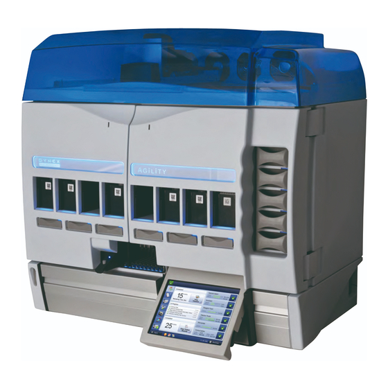
Chapter 1 Overview Chapter 1 Overview 1.1 Introduction The Agility Automated ELISA Processing System (Figure 1-1) is a flexible, high capacity system to perform a broad range of automated ELISA assays. The operator simply inserts packaged SmartKits that contain all of the reagents, standards and related fluids as well as assay information (Section 1.2) that are required for the assay into the ports on the front panel. -
Page 10: Smartkit
Chapter 1 Overview 1.2 SmartKit The heart of the Agility Automated ELISA Processing System is the SmartKit™, which is a reagent pack that is designed to hold bottles that contain the fluids that are required to perform the assay. A SmartKit™ includes a two-dimensional barcode label that includes the details of the assay, data reduction and reporting as well as lot information, usage volumes and pack layout. -
Page 11: Sample Rack
Chapter 1 Overview 1.3 Sample Rack Samples are placed in a sample rack which is loaded into the system via a sample rack loader (Figure 1-3) which houses a barcode reader and sensors for tube detection and tube size detection. 10 sample tube racks which each hold 20 sample tubes are provided; each rack holds sample tubes with physical dimensions of External Diameter 10-17mm, Internal Diameter 8-14mm, Height 40-100mm. -
Page 12: Consumable Supplies
The sample and reagent pipette tips are defined as accessories as only the Caution. DYNEX tips have been found to meet the stated precision and accuracy specifications Consumable supplies are placed into the system via the five consumable drawers on the right side of the system. - Page 13 Chapter 1 Overview Figure 1-6: Reagent Tip Rack c) Deep Well Strip Holder - The deep well strip holder (Figure 1-7) holds 12 deep well strips for the system to perform deep well pre-dilutions of controls and samples. The deep well strip holder is loaded on to a consumable drawer and may be loaded in either orientation that fits into any of the four locations on a drawer.
- Page 14 Chapter 1 Overview d) Reagent Mixing Wells and Holder - The reagent mixing holder holds 18 reagent mixing wells (6 x 3 wells) for the system to perform reagent mixing. Reagent mixing may be required where a reagent to be dispensed to the plate is made up of two component reagents that are required to be mixed prior to dispense due to time stability of the mixed components.
-
Page 15: Waste
Chapter 1 Overview 1.6 Waste a) Washer Waste Bottle The system has a 1 X 10 L capacity washer waste bottle for holding aspirated wash contents from the system washer. The waste bottle content weight is monitored by a weigh cell to measure the quantity of fluid and trigger user alarm / notification / status of waste bottle contents. - Page 16 Chapter 1 Overview Figure 1-10: Power receptacle area Three more are located in the power switch area in the front on the lower left. Figure 1-11: Power switch area Setup of the port Each port is automatically assigned a name by Windows. However, LIS-Link software only recognizes port names COM1 to COM9.
- Page 17 Chapter 1 Overview From the Windows Start button, right click on Computer to bring up Device Manager. Figure 1-12: Computer configuration Figure 1-13: Device Manager Select the Prolific USB-to-Serial Comm Port. If is not named COM1 to COM9, it must be renamed. COM8 and COM9 are available for LIS-Link and LIMS HOST.
- Page 18 Chapter 1 Overview Figure 1-14: COM Port Selection Figure 1-15: COM Port Properties Agility System Operator’s Manual...
- Page 19 Chapter 1 Overview Click on Advanced. Figure 1-16: Advanced Properties If the COM port name is not assigned COM 1 to COM9, select a proper COM name from "COM Port Number" list. All USB hubs must have power management turned off. In Device Manager, select Universal Serial Bus Controllers (Figure 1-17).
- Page 20 Chapter 1 Overview Figure 1-17: USB Hub Setup Figure 1-18: USB Hub Setup Agility System Operator’s Manual...
-
Page 21: Chapter 2 Safety
Chapter 2 Safety 2.1 Warning Labels The Agility Automated ELISA System and its components contain labels that warn the user of a hazard or an electrical connection. The description of the labels is described below. Potential personal injury to the operator or damage the system can result if the labels are not followed. -
Page 22: Warnings And Safety Precautions
The electromagnetic environment should be evaluated prior to operation of Agility. 12. The sample and reagent pipette tips are defined as accessories as only the DYNEX tips have been found to meet the stated precision and accuracy specifications 13. - Page 23 Chapter 2 Safety 14. If Agility is used in an unspecified manner, the protection provided by the equipment may be impaired. 15. Do not position Agility so that it is difficult to disconnect it from the power supply. 16. Do not use decontamination or cleaning agents that could cause a HAZARD as a result of reaction with parts of the equipment or with material contained in it.
- Page 24 Chapter 2 Safety This page intentionally left blank. Agility System Operator’s Manual...
-
Page 25: Chapter 3 System Design
Chapter 3 System Design Chapter 3 System Design 3.1 Overview The system performs all operations (e.g. sampling, dilution) on an automated basis to meet the requirements of the worklist. There are two workspaces which contain the appropriate items (e.g. microplates, SmartKits , tip packs) to perform a given step and a transport arm which moves the items to and from the storage racks to the workplace. -
Page 26: Upper (Reagent) Workspace
Chapter 3 System Design 3.2.2 Upper (Reagent) Workspace The Upper (reagent) workspace (Figure 3-2) has four locations capable of holding reagent packs or reagent tips and two locations capable of holding microplate holders, deep well strip holders or mixing well holders. Figure 3-2: Upper (Reagent Workspace) Agility System Operator’s Manual... -
Page 27: Transport Arm
Chapter 3 System Design 3.3 Transport Arm The robotic transport arm (Figure 3-3) transports the various consumables around the instrument locations at times required to perform the operations defined by the controlling software and the worklist. The transport arm has gripper arms for positive locking and moving the consumable holders around the system. -
Page 28: Sample Pipettor Arm
Chapter 3 System Design 3.4 Sample Pipettor Arm 3.4.1 Overview The sample pipettor (Figure 3-4) arm performs the following operations: Gets a new sample tip from the sample tip rack Ejects used sample tips into tip waste container evenly ... -
Page 29: Tip Detection
Chapter 3 System Design The sample pipettor picks up a tip from a sample tip consumable box located on the lower workspace and ejects the tip to the tip waste reservoir. The tips are ejected using four eject pegs spaced along the tip waste reservoir. When ejecting tips, the nearest post to where the last tip dispense was performed is used. -
Page 30: Reagent Pipettor Arm
Chapter 3 System Design 3.5 Reagent Pipettor Arm 3.5.1 Overview The Reagent Pipettor arm (Figure 3-6) is used for the following operations: Get a new reagent tip from the reagent tip rack Eject a used reagent tip back to the reagent tip rack ... - Page 31 Chapter 3 System Design Disposable reagent tips are used to dispense reagent fluids on the instrument. Reagent tips are in a rack of 98 tips as shown in Figure 1-6 and loaded through the Consumables drawers on the right side of the instrument. Reagent tips are to be picked up by the reagent pipettor from tips housed in the rack boxes.
-
Page 32: Reagent Dilution
Chapter 3 System Design 3.5.2 Reagent Dilution Dilution and pre-dilutions of sample / control fluids in a deep well can be performed using the following 1 in ..The user programs a dilution using the ratio 1 in ... selection. The software calculates both parts of the dilution fluid amounts required based on this ratio. -
Page 33: Sample Loading Module
Chapter 3 System Design 3.6 Sample Loading Module The sample racks are designed to go through a sample rack loader which houses a laser barcode reader and a laser with sensors for tube detection and tube size detection (see Figure 3-1). -
Page 34: Consumable Drawers
Chapter 3 System Design 3.7 Consumable Drawers The system has five user removable drawers that are capable of holding four consumable racks. The drawers are on the right side of the instrument and slide out. A typical drawer is shown in Figure 3-6. Figure 3-6: Consumable Drawer The consumable drawers are capable of holding sample tip holders that hold 112 tips, deep well strip holders capable of holding 12 deep well strips and a reagent mixing vessel holder... -
Page 35: Microplate Washer
Chapter 3 System Design 3.8 Microplate Washer The system incorporates a microplate washer module (Figure 3-7). The system washer has an 8-way wash head capable of dispensing to a standard microplate strip format. The Wash Head floats mechanically (minimum of 3 mm) to allow for any inaccuracy of matching the wash head to the plate. - Page 36 Chapter 3 System Design The product wash module has the ability to wash the plate in different wash modes: a) Plate-Wise In a Plate-Wise wash mode each cycle is performed across the entire plate. The first cycle aspirates and dispenses to strip 1 followed by aspiration and dispensing to strip 2, following this procedure through to strip 12.
- Page 37 Chapter 3 System Design The product wash module has the ability to aspirate the plate with different sweep modes. a) No Sweep There is no side sweep and the well is aspirated only from the center. b) Sweep On each cycle of the plate, the well is aspirated while the wash head moves left to right. c) Sweep on Last Cycle On the last dispense cycle of the plate only the well is aspirated while the wash head moves left to right.
- Page 38 Chapter 3 System Design The washer has a constant timing option. The constant timing option treats each cycle of the plate timing to be as if it is washing all 12 plate strips even if fewer strips are required to be washed. As an example if a plate is run that only has enough samples tested that would fill 32 test wells (four strips) then the four strips would be washed as per programmed and then the wash head would wait for a period of time that it would take to perform the wash operation on the remaining eight strips before returning to start the next...
-
Page 39: Microplate Reader
Chapter 3 System Design 3.9 Microplate Reader The Microplate Reader (Figure 3-8) is used to make Optical Density (OD) readings on wells in a plate and includes six filters in the range between 405 and 690 nm. Figure 3-8: Microplate Reader The reader is capable of reading in Single / Dual and Multi-Wavelength Modes a) Single Wavelength Mode This mode reads the plate using a single test filter wavelength and the readings are... -
Page 40: Temperature Incubators
Chapter 3 System Design The Reader can of reading values in the range -0.100 to 3.500 OD with the following specifications Precision < 1% CV (<2.0 OD) < 1.5% CV (2.0-3.0) OD Linearity ± 1% at 0.000 to 2.500 OD ... -
Page 41: Front Doors
Chapter 3 System Design The operating temperature of each incubator is ambient (no more than + 4°C from the lab ambient temperature) to 45°C. Each incubator chamber maintains its temperature to ± 0.5ºC. All wells on a flat-bottomed microplate containing 200 µL of H O are within ±... - Page 42 Chapter 3 System Design This page intentionally left blank. Agility System Operator’s Manual...
-
Page 43: Chapter 4 Operating The Agility System
Chapter 4 Operating the Agility System Chapter 4 Operating the Agility System 4.1 Overview This chapter presents an overview of how a typical series of assays is set up and performed by the Agility system. It includes a discussion about how: ... - Page 44 Chapter 4 Operating the Agility System provided to supply information such as assay files to the Agility and to send data to an external device. The touchscreen may be positioned at an adjustable angle for best viewing via a latch on the lower right side frame.
-
Page 45: Powering Up The Instrument
Chapter 4 Operating the Agility System 4.2 Powering up the Instrument When the system is powered up, the internal computer that controls the system will boot with the Windows 7 operating system and automatically present the user with the screen shown in Figure 4-1. -
Page 46: The Home Screen And The Instrument Self Test Procedure
Chapter 4 Operating the Agility System 4.3 The Home Screen and the Instrument Self Test Procedure When the Home screen (Figure 4-2) is presented, a number of self tests will be automatically performed. The results of the self tests will be presented on the screen, along with additional support information. -
Page 47: Filter Setup
Chapter 4 Operating the Agility System When the start-up tests are successfully completed, the buttons on the left side of the screen will be activated and the message Initializing will disappear. At this time the system is ready for the user to proceed. 4.4 Filter Setup The Agility system is factory configured to have wavelength filters installed on the six –... -
Page 48: System Dashboard
Chapter 4 Operating the Agility System Reader Over/Under Specification On this page the highest OD reading permitted as valid for reporting is designated as Over Range. This has not yet been implemented in Agility version 1.0.4. 4.5 System Dashboard To access the user interface, press the Dashboard button to present the Dashboard which is a snapshot of the system status (Figure 4-4). -
Page 49: Preparing The System For Operation
Chapter 4 Operating the Agility System 4.6 Preparing the System for Operation 4.6.1 Empty Waste Liquids and Used Tip Containers The Waste Fluid container and the Washer Fluid containers are located behind the left bottom panel (Figure 4-5). The operator should ensure that the Waste Fluid container is empty and there is sufficient Washer Fluid to perform the desired assays. -
Page 50: Start-Of-Day Assays
Chapter 4 Operating the Agility System Press the Fluids Status region of the Desktop (Figure 4-6) to view the status of the Waste Fluid and Washer Fluid containers (Figure 4-7). Figure 4-6: Fluids Status Region of the Desktop Figure 4-7: Fluids Status Screen 4.6.2 Start-of-Day Assays At the beginning of a session the fluid lines should be primed and conditioned to ensure proper volume delivery. - Page 51 Dispense Assay, the plate will be left full of fluid. Operators should verify wells are filled evenly. Dynex recommends repeating the Dispense Assay for all wash bottle positions that will be used during the course of the worklist to verify bottle and tubing functionality. After performing the Dispense Assay(s), perform the Aspirate Assay.
- Page 52 Chapter 4 Operating the Agility System Figure 4-9: Wash Assay Screen Agility System Operator’s Manual...
- Page 53 Chapter 4 Operating the Agility System Empty the Used Tip Container The Used Tip container is located behind the right lower panel (Figure 4-10). The operator should ensure that the container is empty. Figure 4-10: Tip Waste Container Agility System Operator’s Manual...
-
Page 54: Loading Samples And Consumables
Chapter 4 Operating the Agility System 4.7 Loading Samples and Consumables Note: When a worklist is generated (Section 4.6), the system will check that the required consumables, reagents, samples are present. When an item is loaded, the system inventory is updated and compared to what is required for the performance of the worklist. - Page 55 Chapter 4 Operating the Agility System Check that the Quiet Zone is sufficiently wide at both ends of the barcode label. This distance must be at least 5 mm from the actual barcode to the end of the label. Be sure that the Quiet Zone is not reduced at the corner of a plate;...
- Page 56 Chapter 4 Operating the Agility System Figure 4-11: Sample Rack with Sample Tubes 2. While depressing the handle button, move the Sample Loading Handle (Figure 4-12) to a slot with a white indicator light and slide the rack slowly and steadily into the rack guide until the rack locks in place.
- Page 57 Chapter 4 Operating the Agility System 3. The system will detect that the rack has been inserted and will have read the position, diameter height and barcode label of each tube. The LEDs in front of the sample trays indicate the status of the slots: •...
- Page 58 Chapter 4 Operating the Agility System Figure 4-13: Sample Rack Status Screen The green radio button adjacent to a sample name indicates that the tube was read correctly. If a tube was not correctly read, the indicator radio button will flash red (Figure 4-14).
- Page 59 Chapter 4 Operating the Agility System Figure 4-14: Sample Rack Status Screen showing Sample Rack Error Icon The user should remove the rack, check the barcode label positions on the tubes to see they are presented correctly to the laser reader and insert it once again. Empty positions will be indicated by gray radio buttons in the sample rack status screen as shown in Figure 4-14.
- Page 60 Chapter 4 Operating the Agility System Figure 4-15: Sample Rack Status Editing If a sample ID has been entered manually it will be shown with a hatched pattern radio button as shown in Figure 4-16. Agility System Operator’s Manual...
- Page 61 Chapter 4 Operating the Agility System Figure 4-16: Sample Rack Status Screen with manually entered sample ID Agility System Operator’s Manual...
- Page 62 Chapter 4 Operating the Agility System Figure 4-17: Using the Keyboard to Enter Information 6. Additional sample racks should be loaded in the same manner and the sample loading handle should be moved to the new rack position so that the samples are read. ...
-
Page 63: Load Consumables
Chapter 4 Operating the Agility System 4.7.2 Load Consumables The consumables are loaded in the five trays on the right side of the instrument. Up to four consumable drawer items can be loaded on to the drawers. Each Item on the drawer when loaded needs to be a full unused item. - Page 64 Chapter 4 Operating the Agility System 2. Remove used consumables in the drawer and load the drawer with the consumables required for the assay(s) that will be performed (sample pipette tip racks, reagent pipette tip racks, deep well strip racks (if required) and reagent well mixing well racks (if required).
-
Page 65: Load Smartkits
Chapter 4 Operating the Agility System Figure 4-19: Consumables Screen 4.7.3 Load SmartKits SmartKits are loaded into a SmartKit holder and loaded through the rack loading bays on the front doors, barcode end first. The SmartKit holder is keyed to only fit into loading position the correct way. -
Page 66: Load Reagent Tip Racks
Chapter 4 Operating the Agility System SmartKit immediately after ejection. Wait at least five seconds before removing. But the SmartKit needs to be removed within 20 minutes before the next SmartKit is finished and ejected. The system can be set up by trained service engineers to reduce this time but this means the operator must remove the ejected SmartKit before this time or risk proper operation timing of plates and SmartKit processing for the worklists still running on the system. -
Page 67: Performing An Assay
Chapter 4 Operating the Agility System Flashing Blue Light – The indicator will flash blue if a plate is completed and is in Eject position half way out for user to remove from system. The microplate needs to be removed before the next microplate is finished and ejected. - Page 68 Chapter 4 Operating the Agility System As an example, if the microplates that are to be used with the SmartKits that have been loaded are not present, when the scheduling has been accomplished, the system will indicate that a microplate that matches a SmartKit assay is required via a white light indicator surrounding the microplate loading bay.
- Page 69 Chapter 4 Operating the Agility System If desired, the status of various items can be displayed by pressing the appropriate button on the left side of the screen. As an example, if you press the button, the Plate ID screen will be presented (Figure 4-23). Figure 4-23: Plate ID Screen In the example shown above, the assay definition has indicated position A1 is a blank (gray), B1 a negative control (green), C1 through E1 are standards (blue), G1 is a positive control...
- Page 70 Chapter 4 Operating the Agility System Figure 4-24: A Typical Dashboard during System Operation To determine the detailed status of various consumables, press the appropriate area on the right side of the Dashboard screen. 1. Plates Region (top fields) - Presents Figure 4-25, which provides information about the active plate.
- Page 71 Chapter 4 Operating the Agility System Figure 4-25: Plate Information 2. Reagents Region (Second Region) - Presents Figure 4-26 describing the status of the reagents. Agility System Operator’s Manual...
- Page 72 Chapter 4 Operating the Agility System Figure 4-26: Reagents Status 3. Fluids Status (Third Region) – Presents information about the buffers and wash fluids (Figure 4-27). Agility System Operator’s Manual...
- Page 73 Chapter 4 Operating the Agility System Figure 4-27: Fluid Status Make sure the proper fluids and indicated volumes are appropriately filled in the right bottle locations as they are assigned by selecting an item in the Wash Buffer List (which will then be highlighted) and then selecting the graphic representation of the bottle that corresponds to the actual bottle where that fluid has been loaded.
- Page 74 Chapter 4 Operating the Agility System Figure 4-28: Consumables Status Agility System Operator’s Manual...
-
Page 75: Viewing Data
Chapter 4 Operating the Agility System 4.9 Viewing Data To generate a search for data: 1. Press the button to present the Search screen (Figure 4-29). Figure 4-29: Search Screen 2. Enter the desired parameter to define the data to be viewed. A typical results screen is shown in Figure 4-30. - Page 76 Chapter 4 Operating the Agility System Figure 4-30: Typical Results Screen The results can be viewed in a variety of formats by selecting the appropriate button on the left side of the results screen as shown in Figure 4-31. Agility System Operator’s Manual...
- Page 77 Chapter 4 Operating the Agility System Figure 4-31: Data Format Options The various formats are described in Chapter 6. Agility System Operator’s Manual...
-
Page 78: Aborting Plates/Stopping The System/Shutting The System Down
Plate maps will be generated for aborted plates automatically. Plate maps will be located in a time and date stamped subdirectory in the C:\Program Data\Dynex Technologies\Plate folder. Agility System Operator’s Manual... - Page 79 Chapter 4 Operating the Agility System The End-Of-Day option is for shutting down the system at the end of a session. It will prepare the system for its next session. Figure 4-33: Pause Screen – Unlock Doors The front doors may be unlocked to gain access to the interior by selecting the big pause icon on the instrument picture.
-
Page 80: System Shutdown
Chapter 4 Operating the Agility System 4. After completion of the desired operation press the Return button to go back to the home operations screen. To Abort Plates: Select the icon. Select the plates wished to be aborted. Select Abort Plates button. - Page 81 Chapter 4 Operating the Agility System 2. Remove the SmartKits and plates. The indicator lights will change to white. 3. Select Shutdown on the screen. The consumables will be returned to the to the consumables drawers, the drawers will be unlocked and the indicator light will change to pulsing blue.
- Page 82 Chapter 4 Operating the Agility System This page intentionally left blank. Agility System Operator’s Manual...
-
Page 83: Chapter 5 Maintenance And Troubleshooting
Chapter 5 Maintenance and Troubleshooting Chapter 5 Maintenance and Troubleshooting 5.1 Routine Maintenance Procedures Note: Performing maintenance to the Agility system may expose the operator to hazardous moving parts. The following periodic maintenance procedures are required for the Agility System: Daily Maintenance 1. - Page 84 Chapter 5 Maintenance and Troubleshooting Weekly Maintenance 1. Empty the wash buffer containers and rinse them several times with deionized water. Monthly Maintenance 1. Clean surfaces of dust, debris, and spillage. a. With a moist cloth, wipe the consumable drawers and sample tray guides. b.
-
Page 85: Cleaning And Decontamination
Ensure that the system has been decontaminated or take suitable precautions (e.g., wear rubber gloves and suitable eye protection). If the system is sent back to a Dynex Technologies facility, the user must certify that the unit has been decontaminated. -
Page 86: Decontaminating The System
AGILITY, contact DYNEX Technologies. 5.2.3 Components When a component (e.g. the Reader module) is to be returned to DYNEX Technologies, the user is expected to obtain a return authorization number before shipping the unit and must include an Equipment in Transit form (Figure 5-1). For international locations, please contact your local DYNEX Technologies facility. - Page 87 Signed: ____________________________________________ Title: ____________________________________________ Date: __________________ (DYNEX Technologies reserves the right to refuse improperly cleaned equipment) Shipping address: DYNEX Technologies Attn: (Above return number) 14340 Sullyfield Circle Chantilly VA 20151-1683 * Suggested decontamination methods: Readers - Wipe all surfaces with a cloth moistened with 10% bleach or 70% alcohol.
-
Page 88: Replacing The Lamp Assembly And Filters
Chapter 5 Maintenance and Troubleshooting 5.3 Replacing the Lamp Assembly and Filters A lamp has a lifetime of approximately 2000 hours and can be readily replaced by the user. Lamp replacement is described in Section 1.3.2 A 405 nm filter is placed in position 1 of the filter wheel which is mounted on the lamp assembly and additional filters are fitted to meet the requirements of the facility. -
Page 89: Replacing The Lamp
Chapter 5 Maintenance and Troubleshooting 5.3.2 Replacing the Lamp To replace the lamp: 1. Open the door to the Primary Optics Assembly 2. Slide out the Primary Optics Assembly (Figure 5-3). Figure 5-3: Primary Optics Assembly 3. Remove the Reader Lamp Assembly from Lamp Bracket by unscrewing the screws that attach the assembly from the bracket. - Page 90 Chapter 5 Maintenance and Troubleshooting Figure 5-4: Removing the Lamp Assembly 4. Disconnect the lamp harness to the connector on the Motor Plate. 5. Remove the old lamp and place a new lamp in position Note: When replacing the lamp, take care not to get fingerprints or other foreign material on it.
-
Page 91: Replacing The Filter
Chapter 5 Maintenance and Troubleshooting 5.3.3 Replacing the Filter A 405 nm filter is placed in position 1 of the filter wheel (Figure 5-5) which is mounted on the lamp assembly and additional filters are fitted to meet the requirements of the facility. On a periodic basis, it may be necessary to change a filter. -
Page 92: Replacing Tubing
Chapter 5 Maintenance and Troubleshooting 5.4 Replacing Tubing The Fluidics Panel Assembly is located on the lower left of the system (Figure 5-6). Figure 5-6: Location of the Fluidics Panel Assembly Agility System Operator’s Manual... -
Page 93: Removal Of The Fluidics Panel Assembly
Chapter 5 Maintenance and Troubleshooting 5.4.1 Removal of the Fluidics Panel Assembly To remove the Fluidics Panel Assembly: 1. Remove the four screws attaching it to the system (Figure 5-7). 2. Disconnect the Vacuum Tube from the bulkhead as shown in Figure 5-8. Figure 5-7: Fluidics Panel Assembly Connections Agility System Operator’s Manual... - Page 94 Chapter 5 Maintenance and Troubleshooting Figure 5-8 Disconnecting the Vacuum Tubing 3. Disconnect the Pinch Valve tubing from the T connectors Agility System Operator’s Manual...
-
Page 95: Replacing Tubing On The Fluidics Panel
Chapter 5 Maintenance and Troubleshooting 5.5 Replacing Tubing on the Fluidics Panel The tubing on the Fluidics Panel should be replaced as necessary. It is recommended that the tubing be replaced when cloudiness or cracking is observed. The dispense valve tubing is depicted in Figure 5-9. The 45 mm tube end should be connected to the KNF pump outlet. - Page 96 Chapter 5 Maintenance and Troubleshooting Figure 5-10: Connecting the KNF Pump to the Wash Head Manifold After the tubing has been replaces, connect the vacuum tubing and reinstall the entire assembly. Agility System Operator’s Manual...
-
Page 97: Chapter 6 The Graphical User Interface
Chapter 6 The Graphical User Interface Chapter 6 The Graphical User Interface 6.1 Introduction Note: This chapter presents a detailed description of the graphical user interface and is provided as a reference tool. The operator should refer to Chapter 4 for information about the steps that are required to perform an assay. - Page 98 Chapter 6 The Graphical User Interface Figure 6-1: The Administrator Screen Agility System Operator’s Manual...
-
Page 99: The Home Screen
Chapter 6 The Graphical User Interface 6.3 The Home Screen When an Operator login is employed or the Agility field on the Options screen is selected, the Home screen (Figure 6-2) will be presented. Figure 6-2: The Home Screen When the Initialize All Modules button is selected, the self-test, the homing procedure and the recognition of the status of all modules and consumables will be performed. - Page 100 Chapter 6 The Graphical User Interface Figure 6-3: The Startup Status Report Screen The hardware module versions can be viewed by pressing the arrow icon on the top right (Figure 6-4). Agility System Operator’s Manual...
- Page 101 Chapter 6 The Graphical User Interface Figure 6-4: The Version Report Screen Agility System Operator’s Manual...
- Page 102 Chapter 6 The Graphical User Interface The buttons on the left side of the Welcome screen access various parts of the application program and will change as various screens are accessed. The button corresponding to the window that is presently open is indicated in a pale shade while other buttons are indicated in a darker shade.
-
Page 103: The Dashboard
Chapter 6 The Graphical User Interface - The Logout button is used when the present user of the system wants to transfer control to another individual. The Login screen (Figure 6-1) will be presented to allow the new user to log in. When control is passed via the Logout button all present operations are maintained and the new user can edit the program at the level assigned to him/her by the administrator. - Page 104 Chapter 6 The Graphical User Interface The In Progress field indicates the most current five actions and the time for which they were performed or will be performed. The Completed field tells how many tests have been completed in the day’s operation. Agility System Operator’s Manual...
- Page 105 Chapter 6 The Graphical User Interface The buttons on the left side of the Dashboard are used to access additional functions .The present function is presented in a pale color. - Dashboard (this section) - Worklist (Section 6.5) - accesses a screen which lists the various assays to be performed on the samples that have been placed in the system and scanned.
-
Page 106: Worklist
Chapter 6 The Graphical User Interface 6.5 Worklist Pressing the Worklist button (Figure 6-6) begins a sequence of screens to prepare the system for assay processing. The Worklist indicates the assays to be run, the presence of SmartKits and Consumables and lists the assays that have been ordered for the samples placed in the system. - Page 107 Chapter 6 The Graphical User Interface Figure 6-7: The Sample Rack Status Screen The sample rack sample IDs can be viewed by pressing the corresponding green rhomboid button tab at the bottom of the screen. The dot adjacent to the Tube # refers to the status of each sample.
-
Page 108: The Timeline
Chapter 6 The Graphical User Interface 6.6 The Timeline 6.6.1 Overview of the Timeline The Timeline screen (Figure 6-8) presents a visual display of all of the activities that the system is to perform/has performed over the selected time period. A zoomed in view of the timeline is shown by touching and dragging the defining a box on the upper timeline to the area on that timeline for which greater detail is desired. - Page 109 Chapter 6 The Graphical User Interface The icons at the upper right of the screen (e.g. ) indicate the component(s) that are required to initiate the timeline to). These icons will remain until the needed items (microplates and fluids) are loaded. The icons on the left side of the screen are used to determine the status of various aspects of the system (Section 6.4.3).
-
Page 110: Icons On The Timeline Screen
Chapter 6 The Graphical User Interface 6.6.2 Icons on the Timeline Screen The icons on the left side of the time line access additional screens which provide details about various aspects of the system: - Timeline (Section 6.5) - Samples (Section 6.5.2.1) - SmartKits (Section 6.5.2.2) - Plates (Section 6.5.2.3) - Consumables (Section 6.5.2.4) -
Page 111: Samples Rack Status Screen
Chapter 6 The Graphical User Interface 6.6.2.1 Samples Rack Status Screen The Samples Rack Status Screen (Figure 6-10) indicates that status of each sample in each rack. The various racks can be accessed by pressing the rhomboid tabs at the bottom of the screen. -
Page 112: Smartkit Screen
Chapter 6 The Graphical User Interface 6.6.2.2 SmartKit Screen The SmartKit screen (Figure 6-11) lists the reagent packs that are resident in the system along with the type of liquids, volume of each liquid, Kit Lot #, and expiration date for each kit. To select the kit to be viewed, press the appropriate item in the listing. -
Page 113: Plate Status Screen
Chapter 6 The Graphical User Interface 6.6.2.3 Plate Status Screen The Plate Status screen (Figure 6-12) indicates the type of samples on a given plate. In the example shown, position A1 is a blank (gray), B1 a negative control (green), C1 through E1 are standards (blue), F1 is a positive control (red) and the rest are test samples (white). -
Page 114: Consumables Status Screen
Chapter 6 The Graphical User Interface 6.6.2.4 Consumables Status Screen The Consumables Status screen (Figure 6-13) provides information about the contents of the five drawers on the right side of the system. The lock sign indicates that the drawer is locked and in use for current assays, while the unlocked icon indicates that the drawer is not locked and could be restocked by the user. -
Page 115: Incubator Screen
Chapter 6 The Graphical User Interface 6.6.2.5 Incubator Screen The Incubator Status screen (Figure 6-14) presents the present temperature of each of the incubators. Figure 6-14: Incubator Status Screen As shown here there will be an indicator when the temperature does not fall within instrument specifications and may need servicing. -
Page 116: Wash Bottle Status Screen
Chapter 6 The Graphical User Interface 6.6.2.6 Wash Bottle Status Screen The Wash Bottle Status screen (Figure 6-15) presents the level of each of the washer fluid containers and the waste fluid container Figure 6-15: Washer Status Screen Agility System Operator’s Manual... -
Page 117: The Timeline Screen And Status Screens
Chapter 6 The Graphical User Interface 6.7 The Timeline Screen and Status Screens 6.7.1 The Timeline Screen The Timeline screen (Figure 6-16) presents a visual display of all of the activities that the system is to perform/has performed over the selected time period. A zoomed in view of the timeline is shown by touching and dragging the defining a box on the upper timeline to the area on that timeline for which greater detail is desired. - Page 118 Chapter 6 The Graphical User Interface The buttons on the left side of the screen access a variety of screens that provide information about the present status of the system as described in Section 6.4. The Log Viewer Screen The Log Viewer screen (Figure 6-17) presents the ability to query and view the listing of events that have been recorded while the system is running.
-
Page 119: Results
Chapter 6 The Graphical User Interface 6.9 Results The Results screen is used to present the results of the assays. The data can be presented in a number of formats as described in this section. When the Results icon is selected, the Results Data Base Search screen (Figure 6-18) is presented. - Page 120 Chapter 6 The Graphical User Interface After the desired search parameters have been selected and the Display Results button is pressed, the Results Summary table is presented (Figure 6-19). Note: The format of the Results Summary table is dependent on the Search Parameters that have been selected.
- Page 121 Chapter 6 The Graphical User Interface The icons on the left side of Figure 6-22 access a broad variety of data formats as described below: - Result Lot Info (Section 6.9.1) - OD Results Table (Section 6.9.2) - Threshold Table (Section 6.9.3) - Ratio Table (Section 6.9.4) - Curve Fit Table (Section 6.9.5) - Curve Fit Graph (Section 6.9.6)
-
Page 122: Result Lot Table
Chapter 6 The Graphical User Interface 6.9.1 Result Lot Table The Result Lot table (Figure 6-20) presents information about the assay conditions used to generate the data and is not editable. Figure 6-20: Assay Lot Editor Agility System Operator’s Manual... -
Page 123: Od Results Table
Chapter 6 The Graphical User Interface 6.9.2 OD Results Table The OD Results table (Figure 6-21) presents the raw data, statistical information and the results of the assay. It also indicates if the raw data meets the quality control requirements of the assay. -
Page 124: Threshold Table
Chapter 6 The Graphical User Interface 6.9.3 Threshold Table The Threshold table (Figure 6-22) presents the raw data, statistical information and the results of the assay. It also indicates if the raw data meets the pass/fail requirements of the assay using the equation(s) in the assay protocol. -
Page 125: Ratio Table
Chapter 6 The Graphical User Interface 6.9.4 Ratio Table The Ratio table (Figure 6-23) presents the raw data, statistical information and the results of the assay. It also indicates if the raw data meets the Ratio equation requirements of the assay using the equation(s) in the assay protocol. -
Page 126: Curve Fit Table
Chapter 6 The Graphical User Interface 6.9.5 Curve Fit Table The Curve Fit table (Figure 6-24) presents the data used to generate calibration curve used for the assay. Figure 6-24: Curve Fit Table Agility System Operator’s Manual... -
Page 127: Curve Graph
Chapter 6 The Graphical User Interface 6.9.6 Curve Graph The Curve Graph (Figure 6-25) presents a graphical representation of the calibration data. Figure 6-25: Curve Graph Outliers may be removed and the standard curve recalculated. All results will also be recalculated and a new report may be generated. -
Page 128: Spreadsheet
Chapter 6 The Graphical User Interface Figure 6-26: Outlier Removal 6.9.7 Spreadsheet This view presents spreadsheet function table information. Agility System Operator’s Manual... -
Page 129: Pause/Stop/Abort
Chapter 6 The Graphical User Interface Figure 6-27: Spreadsheet View 6.10 Pause/Stop/Abort Note: A detailed discussion of the Stop operations can be found in Section 4.3. The sequence to Pause, Abort Plates or Stop the System is initiated by the button which presents the Stop/Abort screen (Figure 6-28). - Page 130 Plate maps will be automatically exported for aborted plates. Files will be located in a date and time stamped subfolder in the C:\Program Data\Dynex Technologies\Plate folder. The End-Of-Day option will return all unused plates and SmartKits. It will reset all consumables and prepare the system for its next session, shutting the system down.
-
Page 131: Utilities Screens
Chapter 6 The Graphical User Interface The Create Plate Maps option will export plate maps in .xml format for all plates scheduled on the system. Files will be located in C:\Program Data\Dynex Technologies\Plate. 6.11 Utilities Screens Various utilities may be accessed from the Home screen. - Page 132 Chapter 6 The Graphical User Interface Figure 6-30: SmartKit Utilities Kit Lot Information Screen A “Gold” SmartKit will have two sets of labels. The two smaller barcodes on the top have information about the assay. The larger barcode label underneath will contain descriptive information about reagent lot, including such things as expiry date, individual correction factors and standard values.
- Page 133 Chapter 6 The Graphical User Interface Figure 6-31: SmartKit Utilities Fluid Lot Information Screen The layout of the fluids in the SmartKit is shown here. This screen also allows the entry of lot number and expiry date of the fluids in the kit. This information is stored in the database by clicking on the printer icon which also will print out a label to the label printer.
- Page 134 Chapter 6 The Graphical User Interface Figure 6-32: File Management Screen (Transfer files) The drop-down menu has four available functions. The first is the ability to load files from the USB flash drive to the Agility system or from the folder C:\assays on the hard drive. Clicking on the Current USB Device will toggle between the two locations.
- Page 135 Chapter 6 The Graphical User Interface Figure 6-33: File Management Screen (Assay selection) The second item in the drop-down box allows the selection of the specific version of the assay to be used if there is more than one assay that uses the same SKD (SmartKit Definition) file. Clicking on the white down arrow on the gray title bar will bring up any multiple assays assigned to that SKD.
- Page 136 Chapter 6 The Graphical User Interface Figure 6-34: File Management Screen (Report Profile assignment to an Assay) Clicking on the black arrow will show how a Report Profile can be assigned to a particular assay. Any profiles created will appear in the drop-down list. If the Use Assay selection is made, reports will be produced from the assay as originally created with Assay Editor.
- Page 137 The instrument may be configured to turn on the audible alerts and errors that are also shown via the icons visible on the user interface. These are .wav files that may be found here: C:\ProgramData\Dynex Technologies\Sounds\alert.wav C:\ProgramData\Dynex Technologies\Sounds\error.wav If a different sound is wanted, new .wav files can be put in these locations with those same names.
- Page 138 Chapter 6 The Graphical User Interface Figure 6-36: User Configuration (Laboratory Information) The information on this input screen will be inserted into reports if desired. Agility System Operator’s Manual...
- Page 139 Chapter 6 The Graphical User Interface Figure 6-37: Reader Configuration The reader filters are configured at the factory but may be changed. This screen designates where the new filters are inserted on the filter wheel. The criteria for what is displayed as an “Over” reading and how to specify what value should be provided for either “Over”...
- Page 140 Chapter 6 The Graphical User Interface Figure 6-38: Report Profiles Report profiles can be set up and saved using this screen. Multiple profiles can be associated with any assay. Using the input for Over Incubation Tolerance any incubation that runs longer than the nominal assay definition according to this input will be inserted into the report.
- Page 141 Chapter 6 The Graphical User Interface Figure 6-39: Over Incubation Warning If the Report Profile is not used for reporting, the default report format defined in the assay will be used. The input shown above will insert a warning if any incubation runs longer than the nominal assay definition according to this input.
- Page 142 Chapter 6 The Graphical User Interface Figure 6-40: Logging Purge Setting As logs can be quite lengthy and consume a lot of disk space, the setting shown here will continuously purge older logs. Agility System Operator’s Manual...
-
Page 143: Chapter 7 Error Handling
Chapter 7 Error Handling Chapter 7 Error Handling 7.1 Introduction The user will be presented with error message screens should there be a problem in operation. The display will guide the user to the proper actions. Figure 7-1: Example Error Recovery Dialog Agility System Operator’s Manual... - Page 144 Chapter 7Error Handling This page intentionally left blank. Agility System Operator’s Manual...
-
Page 145: Appendix A Specifications
Appendix A Specifications Appendix A Specifications System Specifications Number of Plates 12 (additional packs can be added using continuous load capacity) Number of Sample Tubes Number of Reagents Up to 16 SmartKit Reagent Packs simultaneously (additional packs can be added using continuous load capacity) Number of Pipettes 2 (sample + reagent) Sample Pipetting Specifications... -
Page 146: Reader Specifications
Appendix A Specifications Reader Specifications Photometric Range 0.000 to 3.500 OD Spectral Range 405 to 690 nm ± 0.010 OD at 0.000 – 0.500 OD Precision < 1% CV between 0.501 OD and 2.0 OD < 1.5% CV between 2.01 and 3.0 OD ±... -
Page 147: Regulatory Compliance
Appendix A Specifications A.7 Regulatory Compliance Electromagnetic Perturbation EMC Directive 2004/108/EC EN 61326-2-6:2006 EN 61326-1:2006 Electrical Safety BS EN 61010-1:2001 IEC 61010-1:2001 IEC 61010-2-101 Lead-free All components are RoHS compliant IVDD CE marked per IVD 98/79/EC Directive System Dimensions Width <1250 mm (49”) Depth <900 mm (35”) - Page 148 Appendix A Specifications This page intentionally left blank. Agility System Operator’s Manual...
-
Page 149: Appendix B Consumables And Spare Parts
Appendix B Consumables and Spare Parts Appendix B Consumables and Spare Parts The following items are available from Dynex Technologies or your local Representative Part Number Description Cleaning Wire (.018”) 352101800 352104000 Cleaning Wire (.040”) 47000030 O-Ring Lubricant Silicone 1/2 Oz Tube... - Page 150 Appendix B Consumables and Spare Parts This page intentionally left blank. Agility System Operator’s Manual...
-
Page 151: Limited Warranty
Defective parts and materials will be replaced or, at the discretion of DYNEX TECHNOLOGIES, repaired at no charge for a period of one year and labor required for such replacement or repair will be provided at no charge for a period of one... - Page 152 Limited Warranty THE FOREGOING WARRANTIES ARE EXCLUSIVE AND ARE GIVEN AND ACCEPTED IN LIEU OF ANY AND ALL OTHER WARRANTIES, EXPRESS OR IMPLIED, INCLUDING WITHOUT LIMITATION, THE IMPLIED WARRANTY OF MERCHANTABILITY AND THE IMPLIED WARRANTY OF FITNESS FOR A PARTICULAR PURPOSE. NEITHER PARTY SHALL BE LIABLE TO THE OTHER FOR ANY INCIDENTAL, INDIRECT, SPECIAL, OR CONSEQUENTIAL DAMAGES.
-
Page 153: Index
Index Index Abort a Plate, 129 Incubator Screen, 115 Abort screen, 102 Initialize All Modules button, 99 Aborting Plates, 78 Introduction, 9 Administrator Screen, 97 Annual Maintenance, 84 Lamp Assembly Replacing, 88 Cleaning, 85 Liquid Level Detection, 29 Cleaning the System, 85 Loading Consumables, 54, 63 Completed, 104 Loading Microplates, 66... - Page 154 Index Replacing Filters, 88 Tubing, 92 Temperature Incubators, 40 Replacing Lamp Assembly, 88 Threshold table, 124 Result Lot Info, 121 Threshold Table, 121 Result Lot table, 122 Timeline, 105, 108 Results, 105 Timeline Screen, 117 Results Data Base Search, 119 Tip Detection, 29 Results screen, 119 Tip Waste, 15...
-
Page 155: Dynex Technologies Contact Information
DYNEX Technologies Contact Information DYNEX Technologies, Inc. 14340 Sullyfield Circle Chantilly, VA 20151-1621 Tel: 703 631-7800 800 288-2354 Fax: 703 631-7816 Email: customerservice@dynextechnologies.com techservice@dynextechnologies.com www.dynextechnologies.com Dynex Technologies Ltd Columbia House Columbia Drive Worthing West Sussex BN13 3HD England Tel: +44 (0) 1903 267555 FAX: +44 (0) 1903 267722 E-mail: adminuk@dynextechnologies.com...
Need help?
Do you have a question about the Agility Automated ELISA System and is the answer not in the manual?
Questions and answers