Advertisement
Quick Links
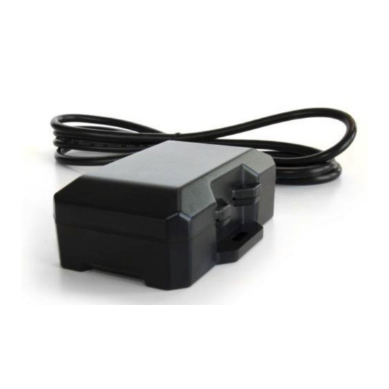
FL12
, 12HP/EQ
™
GPS Tracking Device
KIT CONTENTS:
· FL12/12HD Tracking Device (w/ internal antenna &
integrated harness)
· Power Harness
MOUNTING HARDWARE:
• Plate Mounted Covert:
(1x) FL12 mounting plate (3-1177)
(2x) Serrated flange nuts
(4x) Countersunk screws
• Nose Mount
(2x) #10 x ¾" TEK self-drilling screws
ADDITIONAL REQUIRED HARDWARE
(NOT INCLUDED):
• (3x) 16-22ga. ring terminals
• 6" zip-ties
™
IMPORTANT NOTE:
The switched power source should read 0v
with the key in the off position and 11- 14v in
the on position. For EQ installations, a 5-wire
relay (not included) must be installed
CAUTION:
Us the vehicle's factory service manual and
a digital voltmeter to be sure that you've
located the appropriate wires.
REMEMBER:
When properly installed there must be an
unobstructed line of sight between the
device's antenna and the sky. Any metallic
objects that are positioned above the device
could interfere with GPS reception.
WIRE DESCRIPTION
DEVICE HARNESS:
Black – Power Harness (Black)
Red – Power Harness (Red)
Blue – Input 1 (- trigger)
Orange – Input 2 (- trigger)
POWER HARNESS:
Brown – J560 Pin #6
Blue – J560 Pin #7
White – J560 Pin #1
©2017 Spireon, Inc. All rights reserved.
Advertisement

Related Manuals for Spireon FleetLocate FL12


Summary of Contents for Spireon FleetLocate FL12
- Page 1 Red – Power Harness (Red) Blue – Input 1 (- trigger) Orange – Input 2 (- trigger) POWER HARNESS: Brown – J560 Pin #6 Blue – J560 Pin #7 White – J560 Pin #1 ©2017 Spireon, Inc. All rights reserved.
- Page 2 · DO NOT weld the entire plate NOSE MOUNT: · Place the FL12 on the forward facing bulkhead, harness- side down, directly above the J560 receptacle · Secure the FL12 using two self-tapping screws ©2017 Spireon, Inc. All rights reserved.
- Page 3 J560 plate · Drill both holes using a 5/16” drill bit · Secure the FL12 to the J560 plate, with the harness side down, using two #10 screws and two serrated flange nuts ©2017 Spireon, Inc. All rights reserved.
- Page 4 · Tie a fish line to the end of the device harness and pull it through the access hole under the cable channel below the J560 · Cut the zip-ties from the trailer harness, insert the device harness into the existing split loom and add new zip-ties J560 Housing Cable Channel Access Hole FL12 ©2017 Spireon, Inc. All rights reserved.
- Page 5 · Feed the device harness throught the J560 housing’s cover stock cable grommet QUICK TIP: For help with unconventioanl installations, please contact you account manager or call Spireon technical support, toll-free, at: 877.819.0015. ©2017 Spireon, Inc. All rights reserved.
-
Page 6: Important Note
· Remove the nut on the terminal for pin #7 in the j560 (AUX/ABS) and connect the ring terminal from the power harness’ blue wire POWER HARNESS DIAGRAM: To Device Harness ©2017 Spireon, Inc. All rights reserved. - Page 7 · Connect the blue signal wire from the relay socket harness to the blue wire in the device harness Fig.1 Starter Circuit Ignition Switch 86 – Ground 85 – Ignition Fuse Box 87 – Ground 87a – Unused Relay 30 – Trigger Device ©2017 Spireon, Inc. All rights reserved.
-
Page 8: Led Verification
– both LEDs should stop flashing and light up continuously SPIREON MOBILE INSTALLER PORTAL: · After verifying the LED patterns, log-on to the Spireon Mobile Installer Portal at install.spireon.com to validate the installation · Enter your username and password ·...
Need help?
Do you have a question about the FleetLocate FL12 and is the answer not in the manual?
Questions and answers