Table of Contents
Advertisement
Quick Links
Advertisement
Table of Contents
Troubleshooting

Related Manuals for PerkinElmer AVIO 200


Summary of Contents for PerkinElmer AVIO 200
- Page 1 ICP OPTICAL EMISSION 200 S PECTROMETER Hardware Guide...
- Page 3 Avio 200 Spectrometer Customer Hardware and Service Guide...
- Page 4 The information contained in this document is subject to change without notice. Except as specifically set forth in the terms and conditions of sale, PerkinElmer makes no warranty of any kind with regard to this document, including, but not limited to, the implied warranties of merchantability and fitness for a particular purpose.
-
Page 5: Table Of Contents
Contents Customer Service ..............11 Safety and Regulatory Information . - Page 6 WEEE Instructions for PerkinElmer Products ........
- Page 7 Contents Monochromator ..............73 Detector .
- Page 8 Contents Installing the Quick-Change Adjustable Torch Module ........116 Connecting the Scott Spray Chamber .
- Page 9 Contents Performance Checks ............. 171 Cleaning the Sample Introduction System .
- Page 10 Contents Disassembling the Cross-Flow Nebulizer ..........221 Removing the Sample Tip from the End Cap, N0780546 .
- Page 11 Contents Chiller and Filters ............. . . 258 Fuses .
- Page 12 Contents...
-
Page 13: Customer Service
If you are located within the U.S., call toll free 1-800-762-4000, 8 a.m. to 8 p.m. EST. Your order will be shipped promptly, usually within 24 hours. If you are located outside of the U.S., call your local PerkinElmer sales or service office. -
Page 14: Safety And Regulatory Information
The protection provided by this equipment may be impaired if Caution the equipment is used in a manner not specified by PerkinElmer. La protection fournie par cet équipement risque d'être moins efficace Attention si l'équipement fait l'objet d'une utilisation différente de celle... -
Page 15: Regulatory Information
Regulatory Information Safety compliance Safety information is located in the European Union Declaration of Conformity. Electrical protection Insulation Class I as defined in EN 61010-1. Installation category This instrument is able to withstand transient overvoltage according to Installation Category II as defined in EN 61010-1 and EN 60664-1. Pollution degree This equipment will operate safely in environments that contain nonconductive foreign matter and condensation up to Pollution Degree 2 as defined in... -
Page 16: Environment
Environment Operating Conditions Explosive Atmosphere This instrument is not designed for operation in an explosive atmosphere. Avertissement : atmosphère explosive Warning Cet instrument n'est pas conçu pour fonctionner dans une atmosphère explosive. Pollution Degree This equipment will operate safely in environments that contain non-conductive foreign matter up to Pollution Degree 2 in EN 61010–1. -
Page 17: Symbols Used On The Instrument
When you remove the instrument from storage, before unpacking or putting it into operation, allow it to stand for at least a day under the approved operating conditions. Symbols Used on the Instrument The three different types of warning symbols that appear on the instrument are shown below: Warning This symbol indicates Caution, risk of electric shock. - Page 18 The following graphic symbols are also found on the instrument: Indicates the OFF position of the main power switch. Indique la position Off de l'interrupteur d'alimentation principal. Indicates the ON position of the main power switch. Indique la position On de l'interrupteur d'alimentation principal.
-
Page 19: Warning Labels On The Instrument
Labels on the front of the instrument in the sample compartment Figure A. Location of the glassware label in the sample compartment. Location Instructions for Safety Label #1 in Figure A. Only use PerkinElmer Flat Plate Torch Glassware Seulement utiliser PerkinElmer Flat Plate Torch Verrerie. -
Page 20: Caution Label On The Back Of The Instrument
Location of caution label on the back of the instrument. Marking Location Instructions for Safety Label #1 in CAUTION: This unit contains protective circuitry. Contact PerkinElmer Figure B. qualified personnel before performing any AC line tests. ATTENTION: Cette unit contient les circuits protecteurs. Contactez le personnel é... -
Page 21: Warning Labels On The Left Side Of The Instrument
Warning labels on the left side of the instrument Figure C. Location of warning labels on the left side of the instrument. Marking Location Instructions for Safety Label #1 in Warning - Grounding circuit continuity is vital for the safe operation of equipment. - Page 22 Label #2 in Warning - Equipment needs to be de-energized for 60 seconds to allow safe discharging of capacitors. Figure C. Avertissement: L’équipement doit etre désactivé pendant 60 secondes pour permettre la décharge sure des condensateurs. Label #3 in Warning: To avoid electrical shock, disconnect power cord before servicing.
-
Page 23: Warning Labels On The Right Side Of The Instrument
Warning labels on the right side of the instrument Figure D. Location of warning labels on the right side of the instrument. Marking Location Instructions for Safety Label #1 in CAUTION: Do not restrict air intake or exhaust. Figure D. ATTENTION: Ne limitez pas l’entre d’air. - Page 24 Label #2 in CAUTION: Do not restrict air intake or exhaust. Figure D. ATTENTION: Ne limitez pas l’entre d’air. é ou l’échappement To provide adequate space for ventilation, allow at least 30 cm (12 inches) of free space around the instrument. Do not obstruct the two air filters.
-
Page 25: Warning Labels In The Torch Compartment
Warning labels in the torch compartment Figure E. Location of warning labels in the torch compartment. . Marking Location Instructions for Safety Label #1 in WARNING – Do not defeat interlocks. Figure E Avertissement: Ne pas desengager les enclenchements de securite. The instrument has safety interlocks to protect the operator from exposure to radio frequency and ultraviolet radiation. -
Page 26: Neon Box Label
Label #2 in Risk of hot surfaces. Figure E Risque de surfaces chaudes. Wait until the torch and surrounding surfaces have cooled to room temperature before you touch them. Neon Box Label Figure F. Neon Box Label... -
Page 27: Using This Guide
Using this Guide This manual is your hardware guide to the Avio 200 instrument. Main topics include: • safety practices • preparing your laboratory • a description of the system • installation • maintenance • troubleshooting • error messages Documents to Help You This manual contains hardware information for Avio 200 instrument. -
Page 28: How This Guide Is Organized
To find out about... 1 Safety Practices Important safety information. 2 Preparing Your Laboratory The preparation of your laboratory needed for the Avio 200 instrument. Environmental, electrical, space, exhaust, gases, and cooling water requirements are reviewed. 3 System Description The components of the instrument, how the Echelle spectrometer works and instrument specifications. -
Page 29: Using The Index
A Word on Troubleshooting We recommend that you consult the troubleshooting information included in this manual before you call a PerkinElmer service engineer. The Troubleshooting chapter contains suggestions to help you determine systematically whether instrument problems are due to improper analytical techniques, improper selection... -
Page 31: Chapter 1: Safety Practices
Safety Practices... - Page 32 Safety Practices...
-
Page 33: Introduction
General The protection provided by this equipment may be impaired if Caution the equipment is used in a manner not specified by PerkinElmer. La protection fournie par cet équipement risque d'être moins efficace Attention si l'équipement fait l'objet d'une utilisation différente de celle mentionnée par PerkinElmer. -
Page 34: Environmental Conditions
Warning Cet instrument n'est pas conçu pour fonctionner dans une atmosphère explosive. Handling of the Instrument Contact a PerkinElmer service engineer for assistance in installing or evaluating the system after moving. The Avio 200 weighs 99kg (218 lbs) or 150... -
Page 35: Laboratory Ventilation
The protection provided by this equipment may be impaired if Caution the equipment is used in a manner not specified by PerkinElmer. La protection fournie par cet équipement risque d'être moins efficace Attention si l'équipement fait l'objet d'une utilisation différente de celle... -
Page 36: Safety Interlocks
Safety Practices Safety Interlocks The instrument has safety interlocks to protect the operator from radio frequency (RF) radiation and ultraviolet radiation, and to prevent access to high voltage areas. Do not attempt to defeat the safety interlocks. This would place the operator's safety at risk. -
Page 37: Electrical Safety
This section describes some recommended electrical safety practices. Lethal voltages are present at certain areas within the instrument. Installation and internal maintenance of the instrument should only be performed by a PerkinElmer service engineer or similarly authorized and trained person. Warning When the instrument is connected to line power, opening the instrument covers is likely to expose live parts. - Page 38 Safety Practices Grounding circuit continuity is vital for safe operation of the equipment. Never operate equipment with grounding conductor disconnected. AVERTISSEMENT Warning La continuité du circuit de mise à la terre est cruciale pour la sécurité du fonctionnement de cet équipement. N'utilisez jamais l'équipement avec le conducteur de mise à...
- Page 39 Instrument Safety Practices The instrument must be correctly connected to a suitable electrical supply. The supply must have a correctly installed protective conductor (earth ground) and must be installed or checked by a qualified electrician before connecting the instrument. Any interruption of the protective conductor (earth ground) inside or outside the instrument or disconnection of the protective conductor terminal is likely to make the instrument dangerous.
-
Page 40: High Temperatures
Safety Practices instrument must be operated for further adjustment, maintenance, or repair, this must only be done by a qualified person who is aware of the hazards involved. • Whenever it is possible that the instrument is no longer electrically safe for use, make the instrument inoperative and secure it against any unauthorized or unintentional operation. -
Page 41: Waste Disposal Procedures
Instrument Safety Practices Never place the vessel in an enclosed cabinet. Doing so could result in a build-up of hazardous gases, which may result in a serious explosion or fire. Warning Never use a glass drain vessel. A glass drain vessel may break and spill flammable, toxic, or corrosive liquids. -
Page 42: Weee Instructions For Perkinelmer Products
Requirements for waste collection reuse, recycling, and recovery programs vary by regulatory authority at your location. Contact your local responsible body (e.g., your laboratory manager) or authorized representative for information regarding applicable disposal regulations. Contact PerkinElmer at the web site listed below for information specific to PerkinElmer products. -
Page 43: Safe Handling Of Gas Cylinders
For Customer Care telephone numbers select "Contact us" on the web page. Products from other manufacturers may also form a part of your PerkinElmer system. These other producers are directly responsible for the collection and processing of their own waste products under the terms of the WEEE Directive. -
Page 44: Identification Of Gas Cylinders
Safety Practices If liquid argon or nitrogen is used, the gas cylinder must be fitted with an over- pressure regulator, which will vent the cylinder as necessary to prevent it from becoming a safety hazard. Listed below are some general safety practices for the proper identification, storage, and handling of gas cylinders. -
Page 45: Hazardous Chemicals Warnings
Safe Handling of Gas Cylinders Handling Cylinders • If it becomes necessary to move cylinders, do so with a suitable hand truck after ensuring that the container cap is secured and the cylinder properly fastened to the hand truck. • Use only gas-pressure regulators, tubing, and hose connectors approved by an appropriate regulatory agency. -
Page 46: Safe Use Of Chemical Reagents
Safety Practices Avertissement : certains produits chimiques utilisés avec cet instrument peuvent être dangereux ou le devenir une fois l'analyse terminée. Le responsable (par exemple, le responsable du laboratoire) doit prendre les précautions qui s'imposent afin de veiller à ce que les Warning opérateurs de l'instrument et l'espace environnant ne soient pas exposés à... - Page 47 Safe Handling of Gas Cylinders Give careful attention to the hazards associated with the chemical reagents being used. Refer to the safety data sheets provided by the manufacturer, for example, Material Safety Data Sheets (MSDS) in the USA (for other names, see Reference 5). Warning Avertissement : Accorder une attention particulière aux risques associés avec les réactifs chimiques utilisés.
-
Page 48: Sample Preparation
Safety Practices • The responsible body has the responsibility for carrying out appropriate decontamination if hazardous material is spilt on or inside the instrument. Sample Preparation Sample preparation for ICP spectroscopy may require the handling of organic or corrosive solutions. Dilution of samples and adding dilute acid to a liquid sample is generally less hazardous than putting a solid sample into solution. -
Page 49: Dissolving Solid Samples Using Acids
Sample Preparation • Wear protective clothing and gloves. Some solvents are readily absorbed through the skin. When selecting a solvent, consider the following: • Is the solvent compatible with the equipment? Aliphatic hydrocarbons, ketones and esters, alcohols, and xylene, are the most frequently used solvents. -
Page 50: Acid Digestions
Safety Practices Acid Digestions Acid digestions, either at atmospheric pressure or at increased pressure, require special care. Spattering and foaming of the sample/acid mixture may expose the user to a hazard, as well as compromise the sample integrity. A digested sample containing concentrated acid will react violently with water. - Page 51 Sample Preparation Before using hydrofluoric acid, you should be thoroughly familiar with its hazards and safe handling practices. Observe the manufacturer's recommendations for use, storage, and disposal. Warning Avertissement: Avant d'utiliser l'acide fluorhydrique, vous devriez être familier avec ses dangers et les pratiques de manipulation sécuritaires.
- Page 52 Safety Practices When using high pressure digestion vessels, consult the manufacturer's instructions and recommendations, particularly regarding organic material and possible explosive reactions. Warning Never use perchloric acid in a pressure digestion. Avertissement: Lors de l'utilisation des récipients de digestion à haute pression, consulter les instructions et recommandations du fabricant, notamment en ce qui concerne la matière organique et des réactions explosives possibles.
-
Page 53: Fusion Mixtures
Decontamination and Cleaning Before using any cleaning or decontamination methods except those specified by PerkinElmer, users should check with PerkinElmer that the proposed method will not damage the equipment. Decontamination Customers wishing to return instrumentation and/or associated materials to... -
Page 54: Procedure
Safety Practices The customer's responsible body is required to follow the "Equipment Decontamination Procedure" and complete the "Certificate of Decontamination". These documents are available on the PerkinElmer public website: Procedure: http://www.perkinelmer.com/Content/technicalinfo/dts_instrumentdeconprocedure.pdf Certificate form: http://www.perkinelmer.com/Content/technicalinfo/dts_perkinelmercertificationofdecontaminationform.pdf If you do not have access to the internet and are located in the U.S., call toll free at 1-800-762-4000 or (+1) 203-925-4602, 8:30 a.m. -
Page 55: References
References References 1. Furr, K., ed., CRC Handbook of Laboratory Safety, 5th ed., The Chemical Rubber Co. Press, 2000. 2. National Research Council, Prudent Practices for Handling Hazardous Chemicals in Laboratories, National Academy Press, Washington, D.C., USA, 1981. 3. Compressed Gas Association (USA), "Safe Handling of Compressed Gases in Containers,"... - Page 56 Safety Practices...
-
Page 57: Chapter 2: Preparing Your Laboratory
Preparing Your Laboratory... - Page 58 Preparing Your Laboratory...
-
Page 59: Environmental Conditions
Free of excessive vibration. • Altitude: in the range -400 to 2,000 m (-1,312 to 6,562 feet) The Avio 200 has been designed for indoor use. Do not use the instrument in an area where explosion hazards may exist. Pollution Degree: This product will operate safely in environments that contain nonconductive foreign matter up to Pollution Degree 2 in EN 61010-1. -
Page 60: Exhaust Vent Requirements
Preparing Your Laboratory Exhaust Vent Requirements The Avio 200 requires an exhaust vent to remove combustion fumes and vapors from the torch compartment. Exhaust venting is important for the following reasons: • It protects laboratory personnel from toxic vapors that may be produced by some samples. - Page 61 Preparing Your Laboratory is used, a stronger blower may be necessary to provide sufficient exhaust volume. Alternatively, smooth stainless-steel may be used instead of flexible stainless-steel where flexibility is not required to reduce system friction loss or “drag.” If smooth stainless steel is used, there must be a way to move the vent hood out of the way for servicing.
- Page 62 Preparing Your Laboratory 1. Place exhaust hose over the instrument exhaust connector. 2. Secure the tie wrap around the exhaust hose. Figure 2-1 Location of the Torch Compartment Chimney and Vent. Item Description Top of Instrument Hose Clamp Exhaust Hose...
- Page 63 The minimum door width must be 81 cm (32 in.). Avio 200 Instrument The Avio 200 is 65 cm wide (26 in.), 81 cm high (32 in.), and 76cm deep (30 in.). Figure 2-2 illustrates the dimensions of the instrument. The Avio 200 weighs 99kg (218 lbs), or 150 kg (330 lbs) with the shipping container.
- Page 64 Preparing Your Laboratory Figure 2-2 Outside Dimensions of the Avio 200. Item Description Height 81 cm (32 in.) Depth 76 cm (30 in.) Length 65 cm (26 in.) PolyScience Chiller ® The PolyScience WhisperCool (or equivalent) is usually located on the floor, to the right side of the instrument.
-
Page 65: Cooling Water Requirements
A PolyScience Recirculating Chiller meets these requirements and is recommended ® for the instrument. The PolyScience WhisperCool chiller is available through PerkinElmer in the following two configurations: • 230V, 60 Hz (Part No. N0772046) • 240V, 50 Hz (Part No. N0772045) ®... -
Page 66: Avio 200
être retiré pendant ou après l'installation. • Avio 200 requires an AC line voltage of 200 - 230 VAC +/-10% (180 - 253 VAC) 50/60 Hz. +/-1% under full instrument load, that has a correctly wired protective earthing system (ground connection) and a separate circuit breaker. - Page 67 The instrument will trip the interruptor if this type of outlet protection is used. The Avio 200 is equipped with an IEC60309 250 V 16/20A 2 pole plus protective earth plug (PerkinElmer Part No. 09997530) that inserts into an equivalent...
-
Page 68: Argon
Pneumatic Requirements Argon Liquid or gaseous argon can be used with the Avio 200 system. The use of liquid or gaseous argon tanks is determined primarily by the usage rate. Liquid argon is usually less expensive per unit volume to purchase, but cannot be stored for extended periods. -
Page 69: Shear Gas
The purge gas should be 99.999% pure and is available from local suppliers. Shear Gas Air or nitrogen can be used to shear the plasma for the Avio 200. The Avio 200 RF generator typically consumes the shear gas at a rate of 25 L/min. - Page 70 Preparing Your Laboratory...
-
Page 71: Chapter 3: System Description
System Description... -
Page 73: Introduction
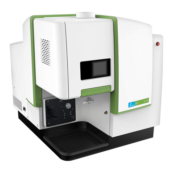
System Description Introduction The Avio 200 instrument consists of three major components: the spectrometer, the ICP Source and the sample introduction system. Each component is further divided into the different modules described below. This modular system design facilitates system access, testing and servicing. - Page 74 System Description Figure 3-1. The Avio 200 Item Description Quick Change Adjustable Torch Module (inside) Peristaltic Pump Viewing Window Spectrometer...
-
Page 75: Introduction
System Description Spectrometer Introduction The core of the optical system is comprised of a dual Echelle monochromator with a dual, backside-illuminated, cooled, CCD detector. The system is specifically designed for ICP-OES. Computer controlled transfer optics direct the radiation from the plasma into the monochromator. The optics housing is sealed and continuously purged with high purity nitrogen. - Page 76 System Description analysis time, the wavelengths required are sorted to minimize the change-over time between any two consecutive wavelengths. The dual monochromator system enables relatively high slits to be used with no loss of image quality, which contributes to the high optical throughput. In addition, part of the slit height is used for the simultaneous measurement of a neon reference spectrum for wavelength correction.
-
Page 77: Detector
System Description Detector The detector is a two-dimensional CCD device containing approximately 25,600 pixels. The photosensitive area is separated into two differently sized arrays that are used for separate reference and analytical measurements. The analytical signal is measured in the larger, lower array. The rear of the actual detector area is thinned to a few micrometers to allow illumination from the rear. - Page 78 System Description Figure 3-3 Detector Item Description Item Description Output CCD Array Register for the reference Output measurement. 2 mm Register for the reference measurement CCD Array 3 mm 3.5 mm...
- Page 79 System Description At 240 nm the array covers a wavelength range of approximately 0.52 nm, and at 850 nm, approximately 25 nm. Thus the emission line for the analyte of interest and emission on each side of the analytical line fall simultaneously on the array. This allows simultaneous measurement of the analyte and background signals.
-
Page 80: Wavelength Correction
ICP Source RF Generator The Avio 200 uses a 40-MHz free-running solid state RF generator. The RF power from the solid state oscillator is used to ionize the argon in the torch and excite the atoms of the liquid sample so that they emit energy at their atomic wavelength in the form of photons. - Page 81 System Description Figure 3-5 Block diagram illustrating the RF Power Control (RFPC) Item Description AC Power Input 40 MHz RF Power Generator RF Power to Plasma Induction Plates Plasma Control Feedback Signal Power Measurement Signal RF Power Control Loop Microprocessor...
-
Page 82: Rf Control Electronics
System Description RF Control Electronics The RF generator uses solid-state circuits. The solid state RF generator is designed to significantly increase reliability and reduce the need for recalibration. The RF generator also monitors plasma conditions. If the plasma is unstable, the system automatically shuts it off. -
Page 83: Nebulizers
This rugged combination provides the best results for a variety of elements and sample types. Nebulizers PerkinElmer offers these nebulizers for a wide variety of applications: Figure 3-6 GemTip Cross-Flow nebulizer and end cap N0780546 (also shown in... - Page 84 System Description Figure 3-7 GemCone nebulizer and end cap N0680343 (also shown in cross-sec- tional view).
- Page 85 System Description Figure 3-8 Concentric glass nebulizer and end cap N0680343 (also shown in cross-sectional view). Description/Part No. Uses/Advantages GemTip Cross-Flow Good general purpose nebulizer for the analysis of strong mineral acids Nebulizer end cap (including HF) and samples with less than 5% dissolved solids. Uses N0780546 GemTips made of sapphire and ruby in a Ryton end cap for maximum chemical resistance.
-
Page 86: Peristaltic Pump
(less than 1%). Self-aspirating. Not to be (MEINHARD) used with solutions containing hydrofluoric acid. PerkinElmer offers four types, Meinhard (A, C, K1 and K3), which are described below. All require an end cap (Part No. N0680343) for use with the Scott spray chambers. -
Page 87: Switches And Controls
System Description Switches and Controls Main On/Off Switch The Main Instrument switch is used to turn on the spectrometer (and is normally left on). Once the plasma has been ignited, you should wait one half hour for the system to stabilize before running samples. Interlocks Interlocks are designed to ensure operator safety and protect the instrument from damage. - Page 88 System Description EMO Switch The Emergency Off (EMO) switch is the illuminated red switch on the front of the instrument. If it is blinking slowly the instrument is in the middle of an ignition cycle. It blinks rapidly after the Emergency Off Switch is depressed. This is an indication that the switch has been depressed and to remind you to push the switch again to release it.
- Page 89 System Description Software Controls Many of the hardware settings are controlled by the software. • RF Power: Power levels can be adjusted in 1-watt increments. • Plasma and auxiliary argon flow rates: Flow rates can be automated during the analysis with specific flow rates for each element if desired. Plasma argon is adjustable in 1 L/min increments.
-
Page 90: Connections To Electrical, Gas, And Cooling Water Supplies
System Description Connections to Electrical, Gas, and Cooling Water Supplies See the following figure. Marking Function Main power switch. Connections for remote control of accessories. Do not exceed the stated voltage and current: Umax = 30 V AC, Imax = 0.5 A AC Umax = 30 V DC, Imax= 2 A DC Line power cord, permanently attached with an IEC 309 connector. - Page 91 Figure 3-10 Electrical, gas, and cooling water connections on the spectrometer side of the instrument . Item Description Item Description Avio 200 Coolant In Terminal Strip (For the Chiller Remote) To Avio In Gas Supply Coolant Supply Hose (Part No. N0770341)
-
Page 92: System Initialization
System Description Item Description Item Description Remote Cable (Part No. N0770175) Line Cord Plug Coolant Drain Hose (Part No. N0770342) Chiller From Avio Out System Initialization When you switch on the spectrometer: 1. The Peltier cooling system for the detector starts to cool the detector. 2. -
Page 93: Technical Data
System Description Technical Data General Inductively coupled plasma optical emission spectrometer. Principle Computer controlled, using a special application program running under a graphical user interface. 200 to 240 V AC ~, 50/60 Hz Power Power consumption 2800 VA (maximum) requirements Insulation: Class I Electrical protection... -
Page 94: Gas Flow Controls
System Description Cooling Water: System requires a flow of 1 gal/min at 310 to 550 kPa at a temperature between 15 °C and 25 °C. A recirculating cooling system is required ® (PolyScience WhisperCool chiller or equivalent is recommended). Automatic Ignition: Plasma ignition is computer controlled and totally automated. The plasma can be turned on at a set time, warming up the system prior to an analysis, and can be turned off automatically after an analysis. -
Page 95: Sample Introduction System
Ryton for complete corrosion resistance to most acids, including HF, and all organic solvents normally used in ICP analyses. The Avio 200 also supports the baffled cyclonic spray chamber and Meinhard K1 nebulizer. This sample introduction system provides the best precision and detection limits. -
Page 96: Optical System
System Description Optical System Monochromator: Wavelength range: 165 nm – 800 nm. High throughput, f/6, dual Echelle monochromator. Echelle grating: 79 line/mm, blaze angle: 63.8 °. Dispersing prism: 30 ° quartz. Spectral bandpass: 0.009 nm at 200 nm, 0.027 nm at 700 nm. -
Page 97: Chapter 4: Installation
Installation... -
Page 99: Installation Summary
Installation Summary Contact a PerkinElmer service engineer for assistance in installing or evaluating the system after moving. The Avio 200 weighs 99kg (218 lbs) or 150 kg (330 lbs) with the shipping container. If the instrument needs to be moved please contact PerkinElmer Service. -
Page 100: Setting Up The Computer And Printer
Moving the Instrument Caution f moving the Avio 200 will subject the instrument to any freezing temperatures you must contact a PerkinElmer service engineer to assist you in the move. The PerkinElmer service engineer will flush all traces of cooling water from the RF generator to prevent freezing of RF generator components. -
Page 101: Connecting The Gases And Cooling Water
Installation • Lift the instrument onto a movable table or put it in the wooden platform originally shipped with the instrument. See the Unpacking Instructions (Part No. 09931178). • Lift into position at the new location. Make sure that the new location complies with the laboratory requirements;... - Page 102 Installation Caution The pneumatic tubing kinks easily. Install it so that it is less likely to twist, fold and kink Les kinks de tubes pneumatiques facilement. Installez-le de sorte qu'il est moins Attention susceptible de se tordre, plier et kink. Connect the gases to the instrument as described in the following procedures.
- Page 103 Installation Figure 4-1. Pneumatic, water and shear gas connections. Item Description Item Description Ar Supply Out (Water Hose with White Tie Wrap) Air/ N 2 Shear Gas Supply In (Water Hose with Red Tie Wrap) N 2 Supply Cooling minimum pressure no maximum...
- Page 104 An air hose (Part No. N0770348) with 1/4-in. Swagelok fittings at each end, is supplied in the hose kit that is shipped with the instrument. A second air hose is also included. The following procedure describes how to connect the PerkinElmer air compressor, filter and regulator.
- Page 105 élevée, les bols de filtre peuvent être arrachés et causer des blessures. The following procedure describes how to set the shear gas pressure when using the PerkinElmer Air Dryer Filter. 1. Make sure the shut-off valve on the Air Dryer Filter is closed (knob turned fully clockwise), then set the air pressure on the air compressor to between 550 kPa and 825 kPa (5.5 to 8.25 bar or 80-120 psig).
-
Page 106: Connecting The Polyscience Chiller
You should be familiar with this manual before proceeding. A qualified electrician must install the single wall receptacle for the Note ® PolyScience WhisperCool chiller. ® The PolyScience WhisperCool is available through PerkinElmer in the following two configurations: 208/230V, 60 Hz 220/240V, 50 Hz... -
Page 107: Connecting The Chiller To The Instrument
The chiller can be turned on or off via the software. Your service engineer will connect the remote cable (Part No. N0770175) from the chiller to the Avio 200 so that the chiller can be operated remotely. To make sure that the chiller can be operated remotely the red wire must be connected to position 9 and the black wire connected to position 11. - Page 108 Installation Figure 4-2 Remote chiller connections. Item Description Avio 200 Terminal Strip Part No. 09987900 (For the Chiller Remote) Instrument Water Hookup Detail 3/8 in. Space Collars (Part No. 09920584) Remote Cable (Part No. N0770175)
- Page 109 Installation Item Description Coolant Drain Hose (Part No. N0770342) White Tie Wrap Coolant Supply Hose (Part No. N0770341) Red Tie Wrap to Chiller In To Avio In Chiller Connection Detail Chiller Figure 4-3 Detail for Remote Chiller Connections Item Description Red wire to position 9 Black wire to position 11...
- Page 110 Initiating the software will have no effect on the chiller if the chiller is already on. If the Avio 200 Spectrometer is in Sleep or Standby mode and the instrument is still ignited, the chiller will remain on. If the instrument is not ignited in Sleep or Standby mode the chiller will turn itself off.
- Page 111 Installation Figure 4-4 Water flow diagram with the chiller Item Description Avio 200 Terminal Strip Part No. 09987900 (For the Chiller Remote) Instrument Water Hookup Detail 3/8 in. Space Collars (Part No. 09920584) Remote Cable (Part No. N0770175)
- Page 112 Installation Item Description Coolant Drain Hose (Part No. N0770342) White Tie Wrap-Water Out Coolant Supply Hose (Part No. N0770341) Red Tie Wrap-Water In Chiller Connection Detail Chiller Filling the PolyScience Chiller ® Use the following procedure to fill the PolyScience WhisperCool Chiller, and refer to the following figure.
-
Page 113: Starting Up The Polyscience Chiller
Installation Figure 4-5 Filling the chiller. Item Description Reservoir Cap Starting Up the PolyScience Chiller ® Check the following before starting up the PolyScience WhisperCool Chiller: • All plumbing connections are tight. • The chiller reservoir is full. • The chiller power cord is plugged in. 1. -
Page 114: Connecting The System Components
Note compromise instrument communication. • The Avio 200 is equipped with an IEC 309 250 V 16/20A 2 pole plus protective earth plug (PerkinElmer Part No. 09997530) that inserts into an equivalent IEC 309 series receptacle (see Section 2, Electrical Requirements). - Page 115 Installation Caution Risk of damage to the instrument. Make sure that signals from accessories connected to the instrument connector do not exceed: Vmax = 30 V AC, Imax = 0.5 A AC Vmax = 30 V DC, Imax = 2 A DC Attention Risque d'endommagement de l'instrument.
- Page 116 Installation Figure 4-6 System component connections Item Description Avio 200 Autosampler RS-232 Cable Part No. B0507701 Computer to Autosampler Ethernet Cable from Computer to Instrument...
-
Page 117: Connecting The Usb Cable For The Plasmacamtm
Installation Item Description Computer Connection From Computer to Printer Printer Monitor Connecting the USB Cable for the PlasmaCam To be able to view the plasma from the ICP software you need to attach the USB cable from the USB connection located at the right side of the instrument to the USB connection on your computer. -
Page 118: Installing The Quick-Change Adjustable Torch Module
The Quick-Change Adjustable Torch Module is shipped pre-assembled as one unit. It includes the torch, spray chamber, injector, and nebulizer. Installing the Quick-Change Adjustable Torch Module Only use PerkinElmer Flat Plate Torch Glassware . Using any other Caution glassware will damage the torch. - Page 119 Installation Figure 4-8 Replacing the torch...
- Page 120 Installation Item Description Torch glass (Part No. N0790131 Torch cutout Knurled Nut (Part No. N0776027) Washer (Part No. N0776028) O-ring (Part No. 09902223) Spacer (Part No. N0791125) O-ring color code blue (Part No. N0791334) Cassette (Part No. N0791285) Stripe on torch Index mark on torch holder...
- Page 121 Installation...
- Page 122 Installation Figure 4-9 Torch Assembly. Item Description Knurled Nut (Part No. N0776027) Injector 2mm Alumina (Part No. N0791183) O-Ring Color Coded Blue (Part No. N0791333) Lock Collar (Part No. N0791163) Washer (Part No. N0776014) O-Ring (Part No. 0992207) Cyclonic Injector Adapter (Part No. N0790143) Scott Injector Adapter (Part No.
- Page 123 Installation 1. Open the torch compartment door. 2. Take the torch cassette body and insert the o-ring, and then the PEEK sleeve (spacer) into it. Ensure that the hole on the PEEK sleeve lines up with the top hole on the torch cassette body. Figure 4-10 O-Rings and Torch Cassette Body Item...
- Page 124 Installation 4. Make sure the holes between the PEEK sleeve and the torch cassette body line up when fully inserted. The holes must line up and be empty, and the PEEK sleeve should not be visible. Figure 4-11 PEEK Sleeve Inserted iin the Torch Cassette Body Item Description Holes Properly Lined up and Empty...
- Page 125 Installation 6. Install the remaining pieces on the PEEK sleeve (spacer): o-ring, PTFE washer, knurled nut, and torch glassware. Fully seat the torch glassware and align the etched rectangle with the alignment mark on the torch cassette body Figure 4-12 Incorrect and Correct Position of the Peek Sleeve Item Description...
- Page 126 Installation 7. Check that the tip of the injector sits below the Aux tube (the inner glass tube) by 1-2mm. 8. For proper alignment, make sure that the mark on the injector (#2) and the line on the torch body (#3) line up. Figure 4-13 Injector Visible Through Torch Item...
- Page 127 Installation 9. Insert the pin of the injector into the groove and rotate it to the right (clockwise) to lock it in place. Figure 4-14 Locking the Injector In Place Item Description Pin in Groove Pin rotated to right (no longer visible). Injector locked in place...
- Page 128 Installation 10. Insert the torch cassette into the instrument. 11. Line up the black line on the torch cassette body with the pin on the instrument. Figure 4-15 Lining up the black line with the locking pin Item Description Sample Compartment Black Locking Pin Black Line for Alignment...
- Page 129 Installation 12. From the bottom of the sample compartment carefully insert the torch cassette. Figure 4-16 Inserting the torch Item Description Item Description Sample compartment Plasma induction plates Torch Compartment Injector Torch Wear gloves when you handle the torch glassware. Caution Attention Portez des gants lorsque vous manipulez la verrerie de la torche.
- Page 130 Installation Figure 4-17 Inserting the torch Item Description Torch Compartment. Torch Not Installed. Plasma induction plates Torch Compartment. Torch Installed. Injector Torch...
- Page 131 Installation 14. As you push the torch into position make sure that the slot on the torch is facing the radial purge window. Figure 4-18 Location of slot on torch Item Description Torch Slot Radial purge window...
- Page 132 Installation 15. Once the torch cassette is in the proper position go back to the sample compartment and push in the black locking pin. This will lock the torch cassette into position Figure 4-19 Location of locking nut Item Description Sample compartment Black locking pin 16.
- Page 133 Installation Figure 4-20 Installing the torch into the sample compartment. Item Description Item Description Inside of the Torch Compartment Ignitor Contact Plastic Air Vent Tube Ignitor Cable...
-
Page 134: Connecting The Scott Spray Chamber
Installation Item Description Item Description Axial Flat Optic Shear Gas Connection Radial Purge Window Plasma Gas Connection Torch Aux Gas Connection Connecting the Scott Spray Chamber 1. After the torch and injector are installed, attach the Scott chamber clip assembly to the bottom of the injector adapter. - Page 135 Installation 3. Find the shelf located on the Scott spray chamber clip assembly. Figure 4-22 Location of Shelf on Scott Spray Chamber Clip Assembly 4. Add the Scott spray chamber clip to the injector. 5. Make sure that the Scott spray chamber clip rests securely on the injector shelf. Figure 4-23 Scott Spray Chamber Clip Assembly in Place...
- Page 136 Installation 6. With the Scott spray chamber clip assembly handle open insert the bottom of the injector adapter into the opening of the Scott spray chamber. Figure 4-24 Scott Spray Chamber Clip Assembly Open Item Description Scott Spray Chamber in Place Scott Spray Chamber Assembly open Opening in Scott Spray Chamber...
- Page 137 Installation 7. Close the clip by pulling it up. This secures the Scott spray chamber into the injector and seals the o-rings. Figure 4-25 Scott Spray Chamber Clip Assembly Closed Item Description Scott Spray Chamber in Place Scott Spray Chamber Assembly closed 8.
-
Page 138: Connecting The Nebulizer (Neb) Tubing
Installation 10. The Scott system is now fully installed. Figure 4-26 Scott Spray Chamber Installed Connecting the Nebulizer (NEB) Tubing To connect the nebulizer (Neb) tubing follow these steps and refer to the next figure. 1. Connect the end of the nebulizer (NEB) argon tubing to the nebulizer end cap and the other end to the quick disconnect by pushing the male quick connect fitting into the quick disconnect. - Page 139 Installation 2. Make sure that the Teflon tubing is in good condition. Replace the tubing if necessary. Connect the sample capillary tubing to the nebulizer sample inlet. Figure 4-27 Nebulizer connections Item Description Item Description Sample compartment Neb tubing Nebulizer end cap Quick Connect 3.
-
Page 140: Connecting The Cyclonic Spray Chamber
Installation Connecting the Cyclonic Spray Chamber Handle the cyclonic spray chamber carefully to avoid breaking the glassware and possible injury. Warning Avertissement: Manipuler avec soin la chambre de nébulisation cyclonique pour éviter de casser la verrerie et des blessures. 1. Install the concentric nebuilzer assembly to cyclonic spray chamber. See Concentric Glass Nebulizer on page 237. - Page 141 Installation Figure 4-28 Installing the Cyclonic Spray Chamber Item Description Injector Clip Cyclonic Spray Chamber 3. The following figure shows the cyclonic spray chamber in place. 4. The white spacer should be installed around the neck of the nebulizer. See the following figure.
-
Page 142: Setting The Torch Position
Installation Figure 4-29 Cyclonic Spray Chamber in Place Item Description Cyclonic Spray Chamber White Spacer Nebulizer Setting the Torch Position After you have installed the torch and spray chamber you will need to set the torch position to get optimal performance. Note: In most cases the optimal position is -3. - Page 143 Installation Figure 4-30 Setting the Position Item Description Latch Open Black Line Beneath -3 Inner Adjustment Plate 3. Once you have reached the desired value, hold the inner adjustment plate in place and lock the latch by pushing the latch in towards the right.
-
Page 144: Installing The Autosampler
Locking Pin Inner Adjustment Plate in Place Installing The Autosampler The instrument can be used with the PerkinElmer S10 Autosamplers. The following procedures describe the electrical connections necessary to install the PerkinElmer autosamplers. After the autosampler is installed, the software must be configured for the type of autosampler you are using. - Page 145 Installation To connect the S10 Autosampler follow this procedure: 1. Locate the connectors on the underside of the autosampler as shown in following figure. Figure 4-32 Electrical connectors and switches located on the underside of the autosampler. Item Designation Function Power Power input socket;...
- Page 146 Installation Figure 4-33 Electrical connection for the S10 autosampler to the Avio 200 Item Description Item Description Avio 200 Connection From Computer to S10 Autosampler...
- Page 147 Installation Item Description Item Description Serial Communication Cable Connection From Computer to Printer S10 Autosampler in Position Printer Detail of Underside of S10 Computer Autosampler Connections 3. Connect the RS232/serial communication cable (Part No. 09290259) provided, between the Com 1 port on the underside of the autosampler (as shown in Figure 4-33 on page 144) and one of the Com ports on the PC.
-
Page 148: Fitting And Connecting The Autosampler Sampling Probe
Installation Fitting and Connecting the Autosampler Sampling Probe When you fit the sampling probe, take care not to press forcefully Caution in any direction on the autosampler arm since this can damage the arm. The sampling probe is a complete assembly. Do not attempt to take the probe apart as this will damage it and reassembly is not possible. - Page 149 Installation Fitting the Sampling Probe 1. If not already done, carefully insert the sampling probe guide from above into the sampling probe holder on the autosampler arm and push it down fully, as shown in the following figure. 2. Carefully insert the sampling probe from above into the probe guide. 3.
- Page 150 Installation Figure 4-34 Inserting the sampling probe. Item Description Sample Tube O-Ring Sampling Probe Sampling Probe Guide Holder About 20 mm Tower...
-
Page 151: Adjusting The Sampling Probe Height
Installation Adjusting the Sampling Probe Height The procedure described below assumes that you are using a spectrometer Note operated via ICP software. If you are using an AA or ICP-MS instrument, please refer to the information on operating an autosampler in the online help for the respective instrument. - Page 152 Installation Figure 4-35 Inserting the sampling probe. Item Description Sampling Probe Rinsing Cup Probe This completes installation of the sampling probe. For detailed information on adjusting the sample probe height and connecting the sample tube between the sample probe and the spectrometer’s sample input system see the S10 Autosamplers User’s Guide (Part No.
-
Page 153: Setting The Torch Viewing Position
Installation Setting the Torch Viewing Position This procedure adjusts the torch viewing position for the highest signal intensity. Perform this procedure when: • the instrument or software is first installed • the instrument is moved to a new location • the torch is removed or replaced •... -
Page 154: Switching On The System
Installation the majority of analyses. -or- Select another element from the drop-down list. This feature is for specialized analyses where you want to optimize the intensity for an individual analyte of interest. This may adversely affect the intensities of other analytes. 12. -
Page 155: Setting Instrument Parameters
Installation 3. Make sure that the torch is correctly installed, the torch compartment door is shut, and the EMO switch is released. 4. Make sure the drain vessel is empty. 5. Switch on the spectrometer, and if required, the autosampler. 6. -
Page 156: Instrument Settings For Aqueous Solutions
Installation Instrument Settings for Aqueous Solutions For Cross-Flow Nebulizers Aqueous Nebulizer Flow: 0.6 L/min RF power 1500 watts Auxiliary Flow: 0.2 L/min Plasma Flow: 8 L/min Sample Flow Rate: 1.5 to 2.5 mL/min Equilibration Time: 8 sec Torch Position For Meinhard Nebulizers Aqueous Nebulizer Flow: 0.7 L/min... - Page 157 Installation Instrument Settings for Organic Solutions Parameter Baffled Cyclonic Spray Chamber, Low-Flow GemCone Nebulizer and 1.2 mm Injector 1500 Watts RF power 0.35 L/min Nebulizer Flow 0.6 L/min Auxiliary Flow 10 L/min Plasma Flow 1.0 to 4.0 mL/min Sample Flow Rate 15 s Equilibration Time Torch Position...
-
Page 158: Hardware Settings And Options
Instructions for removing the window that are given in Removing and Cleaning the Windows on page 199. • PerkinElmer offers different types of nebulizers for a wide variety of applications. For descriptions of the nebulizers and their different uses and advantages, see Nebulizers on page 81. -
Page 159: Shipping List
Installation Shipping List Every day you count on PerkinElmer to provide you with solutions that deliver reliable performance, control operating costs and maximize operational time. Our complete portfolio of consumables, parts, supplies, training and service helps you meet both routine and demanding measurement challenges. We invest heavily in testing and validating our products to ensure you receive guaranteed compatibility and performance - on-time, every time, for every instrument in your laboratory. - Page 160 Installation Table 4-2. Shipping Kit (Part No. N0790011) Part No. Description Quantity 02113330 Product Certification N0770425 Receptacle-AC Power 250 Volt N0790432 Installation Kit N0791214 Shipping Pack N0790210 Instrument Assembly N0790434 Spares Kit N0790607 Torch Assembly-ADJ Cyclonic/Conc Table 4-3. Installation Kit (Part No. N0790432) Part No.
- Page 161 Part No. Description Quantity N0582325 Concepts, Instrumentation and Techniques in ICP-OES (Book) 09931178 Unpacking Instructions for Avio 200 00473550 Flex solvent Tubing (package of 12) 02506516 Round Tygon Tubing B44-3 0.125 ID 0.98 02506532 Round Tygon Tubing F4040A 0.375 ID 0.063...
- Page 162 Part No. Description Quantity N0582325 Concepts, Instrumentation and Techniques in ICP-OES (Book) 09931178 Unpacking Instructions for Avio 200 00473550 Flex solvent Tubing (package of 12) 02506516 Round Tygon Tubing B44-3 0.125 ID 0.98 02506532 Round Tygon Tubing F4040A 0.375 ID 0.063...
- Page 163 Installation Table 4-5. Spares Available (Part No. N0790434)(Continued) 09923037 PVC Pump Tubing 0.045 ID Red-Red 09923383 Cap Sleeve- 0.406 IN BRN Vinyl 09985708 Tube Sleeve 0.032 ID 09985729 PVC Solvent Flex Tubing 0.06 ID Yellow 09985735 PVC Solvent Flex Tubing 0.11 ID Yellow 0.98 09995098 Fan Filter 4.5 SQ Foam...
- Page 164 Installation...
-
Page 165: Chapter 5: Maintenance
Maintenance... -
Page 167: Introduction
You should perform only the maintenance procedures described in this chapter. Record your daily maintenance procedures in the ICP-OES Maintenance Log (Part. No. 09936225). If additional maintenance is required, contact a PerkinElmer service engineer. This instrument requires no specified inspection or preventive maintenance to ensure the continuous functioning of its safety features. -
Page 168: Argon Supply
Nitrogen output pressure: 275-825 kPa (40-120 psig) Shear Gas Supply The Avio 200 requires a supply of shear gas. The shear gas used is typically compressed air; however, nitrogen may also be used. Make sure that an adequate supply of shear gas is available and connected to the system. Check that the supply has sufficient pressure, and that a spare cylinder is ready if necessary. -
Page 169: Torch And Plasma Induction Plates
Maintenance Torch and Plasma Induction Plates Inspect the torch, glassware, and aerosol injector tube. The glassware should be clean, with no traces of deposits or signs of melting. o extend the life and aid in preventing devitrification of glassware, it is Caution necessary to remove all traces of alkali on glassware caused by handling it with bare hands. - Page 170 Maintenance When the pump is not in use, release the pressure plate and release the tubing to prevent flat spots from forming. If you are planning to leave the pressure plate clamped overnight, we recommended that you use the TubingSaver feature. To enable to TubeSaver feature start up the ICP software.
-
Page 171: Periodic Checks
The plasma induction plates must be kept clean to prevent arcing across the plasma induction plates. Inspect the plasma induction plates for any deformations or carbon buildup. Contact your PerkinElmer Service Representative to replace the plasma induction plates if there are any signs of pitting. Pitting causes weakness in the plasma induction plates which can result in a hole in the plasma induction plates and a gas leak. -
Page 172: Nebulizer
Maintenance Nebulizer Check the nebulizer spray pattern with deionized water. Clean or replace the nebulizer as necessary. Spray Chamber Check for leaks around the nebulizer and drain fitting. Inspect the spray chamber for deposits and check the condition of the O-rings. Peristaltic Pump Check that the pump rollers are clean, not scored, free from deposits due to spills, and move freely. -
Page 173: Torch Viewing Position Alignment
Maintenance Torch Viewing Position Alignment The torch viewing position alignment procedure is used to set the plasma viewing position of the spectrometer entrance optics for the highest signal intensity. See Setting the Torch Viewing Position on page 151. Perform this procedure when: •... - Page 174 Maintenance Table 5-1. Recommended Cleaning Procedure (Continued) GemTip or GemCone Clean with soap and water; rinse thoroughly. Nebulizer/End Cap Assembly Concentric Glass Do not use an ultrasonic cleaner. Do not use a cleaning (MEINHARD) wire. See Concentric Glass Nebulizer later in this Nebulizer chapter.
-
Page 175: Quick-Change Adjustable Torch Module
Replacement parts are listed at the end of this chapter. Plasma Torch Caution Only use PerkinElmer Flat Plate Torch Glassware . Using any other glassware will damage the torch. Utiliser uniquement PerkinElmer Plate Flat Torch Glassware Attention L'utilisation de tout autre verrerie endommager la torche. -
Page 176: Plasma Induction Plates
Maintenance Figure 5-1. Quartz Torch. Item Description Plasma Induction Plates Torch Plasma Induction Plates Regularly inspect the plasma induction plates. They should not show any signs of deforming or pitting. If your lab has high humidity, check the plasma induction plates to make sure they are dry. -
Page 177: Removing The Injector
Maintenance Removing the Injector Once the spray chamber has been removed, the injector can be removed without removing the entire torch assembly. To do this procedure follow these steps. 1. Turn off the plasma if it is on. If the plasma has been on, the torch glass will be very hot and can cause serious burns. -
Page 178: Removing And Disassembling The Torch
Maintenance Figure 5-2 Removing the spray chamber assembly and injector. Item Description Scott spray chamber Injector lock Injector Removing and Disassembling the Torch 1. Turn off the plasma if it is on. If the plasma has been on, the torch glass will be very hot and can cause serious burns. - Page 179 Maintenance When installing the Torch Module in the next steps, do so carefully so you will avoid breaking the torch and risking possible injury. Warning Avertissement: Lors de l'installation du module de la flamme dans les prochaines étapes, faire avec soin afin que vous éviter de casser la torche et un risque de blessure possible.
- Page 180 Maintenance Figure 5-4 Removing the torch coupler from the torch mount. Item Description Item Description Sample compartment Plasma induction plates Torch Compartment Injector Torch Wear cotton gloves when you handle the torch glassware. Caution Attention Porter des gants de coton lorsque vous manipulez la verrerie de la torche.
- Page 181 Maintenance 6. Inspect the glassware. If damaged the glassware will have to be removed from the torch cassette. 7. Slide out the injector assembly straight out from the bottom of the torch cassette. 8. Loosen the knurled nut to remove the glassware. Figure 5-5 Torch Glassware in Cassette Item...
- Page 182 Maintenance n the next step, be sure to carefully remove the torch so you will avoid breaking the glassware and risking possible injury. If the torch does break, discard the broken torch and replace. Remove the knurled nut, Warning sleeve and washers on the torch mounting shaft to make sure that all glass fragments are removed.
- Page 183 Maintenance Figure 5-6 O-Rings in Torch Cassette 12. With the injector assembly removed check the O-rings. Replace any that are worn or damaged. There are three O-ring kits: O-ring kit for the Avio Scott injector (Part No. N0790440), O-ring kit for the Avio cyclonic injector (Part N0790441) and the O-ring kit for the Avio Torch (Part No.
- Page 184 Maintenance...
- Page 185 Maintenance Figure 5-7 Torch Assembly. Item Description Knurled Nut Injector 2mm Alumina (Part No. N0791183) O-Ring Color Coded Blue (Part No. N0791333) Lock Collar (Part No. N0791163) Washer (Part No. N0776014) O-Ring (Part No. 0992207) Cyclonic Injector Adapter (Part No. N0790143) Scott Injector Adapter (Part No.
-
Page 186: Cleaning The Torch
Maintenance Cleaning the Torch The torch components should be cleaned regularly to remove accumulated deposits. After prolonged use, a torch may lose its transparency and become crystalline. In this condition, called devitrification, the torch is very fragile. You should not attempt to clean a devitrified torch, but it can still be used. -
Page 187: Replacing The Torch
Maintenance O-rings may be cleaned with soap and water. An ultrasonic bath may be used. Replace if cracked or worn. A torch O-ring kit is available. See the list of replacement parts later in this section. Note: The dark blue torch O-ring (Part No. N0791334) on the outside of the torch and the dark blue O-ring on the outside of the injector adapter (Part No. - Page 188 Maintenance Figure 5-8 Replacing the Torch...
-
Page 189: Replacing The Torch On The Mount
Maintenance Item Description Torch glass (Part No. N0790131) Torch cutout Knurled nut (Part No. N0776027) Washer (Part No. N0776028) O-ring (Part No. 09902223) Spacer (Part No. N0791125) O-ring color code blue (Part No. N0791334) Cassette (Part No. N0791285) Stripe on torch Index mark on torch holder *See the note on page -185. - Page 190 Maintenance Caution Only use PerkinElmer Flat Plate Torch Glassware . Using any other glassware will damage the torch. Utiliser uniquement PerkinElmer Plate Flat Torch Glassware Attention L'utilisation de tout autre verrerie endommager la torche. Before installing the Quick-Change Adjustable Torch Module in the sample compartment, check that the plasma induction plates are in place.
-
Page 191: Scott Spray Chamber
Maintenance 6. If needed, clean the torch, see Cleaning the Torch on page 184. If the torch is cracked or broken carefully dispose of the torch. When installing the Torch Module in the next steps, do so carefully so you will avoid breaking the torch and risking possible injury. - Page 192 Maintenance 3. Disconnect the sample tubing from the nebulizer inlet. Check that the tubing is in good condition and replace if necessary 4. Disconnect the nebulizer argon fitting from the gas fitting on the quick disconnect. 5. Open the Scott spray chamber clip assembly that holds the spray chamber in place.
-
Page 193: Removing The End Cap From The Spray Chamber
Maintenance Removing the End Cap from the Spray Chamber 1. Loosen, but do not remove, the two knurled screws in the nebulizer end cap. Support the spray chamber with one hand as you twist the end cap and end cap ring, together, off the spray chamber. -
Page 194: Cleaning The Scott-Type Spray Chamber
Maintenance Figure 5-10 Spray chamber, end cap, and associated parts. (Illustration shows cross-flow nebulizer end cap assembly, Part No. N0780546.) Item Description Scott Spray Chamber (Part No. N0791499) O-Ring (Part No. 09902033) End Cap Ring (Part No. 00473543) End Cap (Part No. N0681688 not complete assembly) Knurled Screw (2) (Part No. -
Page 195: Replacing The Scott-Type Spray Chamber
Maintenance manufacturer's safety recommendations. These recommendations are normally provided in a material safety data sheet (MSDS) supplied with the chemical. If you have been analyzing organic solutions, the spray chamber can be cleaned using a solvent or diluted soap solution. Be sure to inspect the torch and injector daily for carbon buildup. - Page 196 Maintenance 2. With one hand carefully holding on to the base of the cyclonic spray chamber and with the other hand holding the clip disconnect the clip to remove the spray chamber from the injector. See the following figure. Figure 5-11 Installing the Cyclonic Spray Chamber Item Description...
-
Page 197: Etching The Cyclonic Spray Chamber
Maintenance Etching the Cyclonic Spray Chamber Hydrofluoric acid — toxic and corrosive. Hydrofluoric acid (HF) is toxic, extremely corrosive, and can cause severe burns. Hydrofluoric acid will readily burn skin, and if the fumes are inhaled, lung tissue. Burns may not be immediately painful Warning or visible. -
Page 198: Cleaning The Cyclonic Spray Chamber
Maintenance Cleaning the Cyclonic Spray Chamber If you have been analyzing aqueous solutions, the spray chamber should be cleaned in an acid bath. An ultrasonic bath may be used. Start with a solution of 5% nitric acid or aqua regia and, if deposits persist, increase the acid concentration, up to 20% if necessary. -
Page 199: Replacing The Plasma Induction Plates
If your lab has high humidity, check the plasma induction plates to make sure they are dry. Use a soft dry cloth to dry the plasma induction plates if necessary. Contact your PerkinElmer Service Representative to replace and adjust the plasma induction plates. - Page 200 Maintenance Table 5-3. Replacement Parts: Torch Module (Continued) N0791182 Alumina Injector Straight 1.2 mm N0791183 Alumina Injector, 2.0 mm ID, 150 mm LG (standard injector) N0791184 Sapphire Injector, 2.0 mm ID, 150 mm LG N0791185 Quartz Injector 0.8 mm ID N0791186 Quartz Injector 1.2 mm ID N0791187...
-
Page 201: Windows
Maintenance Windows Removing and Cleaning the Windows If the plasma has been on, the torch will be very hot and can cause serious burns. Wait five minutes after turning off the plasma before you begin these maintenance procedures. Warning Avertissement: Si le plasma a été mis sur, la torche sera très chaude et peut causer des brûlures graves. -
Page 202: Removing And Replacing The Windows
Maintenance Removing and Replacing the Windows These windows are important parts of the optical system. Handle them Caution carefully, as you would any sensitive optical component. Do not directly touch the windows. Always remove the axial window before the radial window and refit the radial window before the axial window. - Page 203 Maintenance If the plasma has been on, the torch glass will be very hot and can cause serious burns. Wait five minutes after turning off the plasma before you begin these maintenance procedures. Warning Avertissement: Si le plasma a été mis sur le verre de la torche sera très chaude et peut causer des brûlures graves.
- Page 204 Maintenance 4. Use the special removal tool to grip the sides of the ring that holds the axial purge window in place. 5. With the tool in place rotate the tool to the left to loosen the stainless steel ring. Figure 5-13 Removing the Axial Purge Window Item...
-
Page 205: Removing And Returning The Radial Purge Window
Maintenance 8. Lift the axial window and ring out of the mount — take care if the spectrometer purge is set to high and you have not removed the axial window — the pressure inside the spectrometer may force out the axial window. 9. - Page 206 Maintenance Tool Required: • Purge window aluminum ring removal tool (Part No. N0790448) 1. Turn off the plasma. 2. In order to gain access to the Radial Purge window you must remove the Shear Gas Nozzle. See Removing the Shear Gas Nozzle on page 207. If the plasma has been on, the torch glass will be very hot and can cause serious burns.
- Page 207 Maintenance Figure 5-14 Location of Radial Purge Windows Item Description Radial Purge Window (Long Radial Purge Window B0810377 Short Radial Purge Window N0690672) 4. Use the special removal tool to grip the sides of the ring that holds the radial purge window in place.
-
Page 208: Cleaning The Windows
Maintenance 9. If the window is dirty clean it by following the procedure Cleaning the Windows on page 206. 10. If the window is damaged, replace with a new radial purge window (Long Radial Purge Window B0810377 or Short Radial Purge Window N0690672). 11. -
Page 209: Replacing And Adjusting The Shear Gas Nozzle
Maintenance Replacing and Adjusting the Shear Gas Nozzle Risk of heat damage to the axial window. Never set the nozzle slit behind Caution the front edge of the axial window mount. Attention Risque de dommages de la chaleur à la fenêtre axiale. Ne jamais régler la fente de la buse derrière le bord avant de la fenêtre axiale de montage. - Page 210 Maintenance 2. Use a T20 Torx screwdriver to remove the two screws that secure the shear gas nozzle in place. See the following figure. Figure 5-15 Location of Shear Gas Nozzle Item Description Shear Gas Nozzle Screw Location Slot Bracket...
-
Page 211: Returning The Shear Gas Nozzle
Maintenance 3. See the following procedure on installing a new shear gas nozzle or replacing the existing shear gas nozzle. Returning the Shear Gas Nozzle Use this procedure to install a new shear gas nozzle or returning the existing shear gas nozzle if you had to remove it in order to replace either the axial or radial purge window. -
Page 212: Adjusting The Position Of The Shear Gas Nozzle
Maintenance Adjusting the Position of the Shear Gas Nozzle Risk of heat damage to the axial window. Never set the nozzle slit behind Caution the front edge of the axial window mount. Risque de dommages de la chaleur à la fenêtre axiale. Ne jamais régler la Attention fente de la buse derrière le bord avant de la fenêtre axiale de montage. - Page 213 Maintenance 2. Locate the Axial Heat Sink Cooling Tube in the torch compartment. Figure 5-16 Location of Axial Heat Sink Cooling Tube Item Description Axial Heat Sink Cooling Tube Black Line on the Axial Heat Sink Cooling Tube 3. Slowly and carefully twist out towards the front of the instrument the Axial Heat Sink Cooling Tube.
-
Page 214: Removing And Replacing The Axial Flat Optic
Maintenance Removing and Replacing the Axial Flat Optic You may need to remove and replace the Axial Flat Optic if you notice reduced Axial sensitivity or counts. Tools Needed: • 6mm Hex Mini Ratchet 1. Turn of the plasma. If the plasma has been on, the torch glass will be very hot and can cause serious burns. - Page 215 Maintenance 4. Disconnect the Axial Flat Optic Temperature Sensor from the instrument. Figure 5-17 Location of Axial Flat Optic Item Description Item Description Axial Heat Sink Cooling Tube Thumbscrew Axial Flat Optic Temperature Sensor Heat Sink Heat Sink Cover...
- Page 216 Maintenance 5. Unhook the cover from the back and slide the cover up and forward to remove. Figure 5-18 Removing Heat Sink Cover Item Description Heat Sink Cover Heat Sink 6. Use the 6mm Hex Mini Ratchet to remove the three screws that secure the Axial Flat Optic in place.
- Page 217 Maintenance 7. Install the new Axial Flat optic and secure with the three screws with the 6mm Hex Mini Ratchet. Figure 5-19 Location of three screws 8. Replace the cover and return the assembly to the instrument. 9. Reattach the Axial Flat Optic Temperature Sensor to the instrument. 10.
-
Page 218: Nebulizers
Maintenance Nebulizers PerkinElmer offers different types of nebulizers for a wide variety of applications. For descriptions of the nebulizers and their different uses and advantages, refer to Chapter 3, System Description. Part numbers and replacement parts for the different types of nebulizers are listed on the next page. - Page 219 Maintenance Table 5-6. Replacement Parts: Nebulizers and End Caps Part No. Description 00472020 MEINHARD Nebulizer (Type A, General purpose) 00473194 O-Ring (for Nebulizer Seal on End Cap) 09902033 O-Ring for Cross Flow Nebulizer End Cap N0680504 End Cap for GemCone Nebulizers N0681574 MEINHARD Type K3 N0690670...
-
Page 220: Gemtip Cross-Flow Nebulizer
Maintenance GemTip Cross-Flow Nebulizer The following procedures cover the maintenance of the GemTip Cross-Flow nebulizer supplied with the instrument. To check the performance of the nebulizer, aspirate a standard and note the intensity reading. If the intensity is significantly lower than it should be, first check that: •... -
Page 221: Removing The Nebulizer/End Cap
Maintenance Removing the Nebulizer/End Cap To remove the nebulizer/end cap assembly: 1. Turn off the plasma if it is on. If the plasma has been on, allow one minute for the Quick-Change Adjustable Torch Module to cool and an additional two minutes for the torch to cool before handling. -
Page 222: Checking The Spray Pattern
Maintenance Figure 5-20 The nebulizer/end cap assembly removed from the spray chamber. Il- lustration shows cross-flow nebulizer end cap assembly. Item Description Cross-Flow GemTip Nebulizer End Cap Assembly (Part No. N0780546) Knurled Screw (Part No. 00473539) Knurled Screw (Part No. 00473539) Spray Chamber (Part No. -
Page 223: Disassembling The Cross-Flow Nebulizer
Maintenance When checking the spray pattern of the nebulizer, pump only use deionized water. Do not use any other solution. Avertissement: Lors de la vérification du motif de pulvérisation du Warning nébuliseur, pompe utiliser uniquement de l'eau déminéralisée. Ne pas utiliser toute autre solution. - Page 224 Maintenance Figure 5-21 Cross-section of GemTip Cross-Flow Nebulizer shown with Cross- Flow End Cap, Part No. N0780546. Item Description Clear GemTip Red GemTip Argon Inlet Sample Inlet To begin disassembling the nebulizer: 1. If you have not already done so, remove the nebulizer/end cap assembly from the spray chamber.
-
Page 225: Removing The Sample Tip From The End Cap, N0780546
Maintenance 2. Disconnect the sample capillary tubing by removing it from the pump tube. 3. Disconnect the nebulizer argon tubing at the gas fitting. Do not disconnect nebulizer argon tubing from the end cap because the GemTip could fall out. 4. - Page 226 Maintenance Figure 5-22 Clear GemTip for sample inlet and associated parts for Cross-Flow End Cap, Part No. N0780546. Item Description Item Description O-Ring (Part No. 09921045) Nut (Part No. 09920546) Clear GemTip Nebulizer 1/16 inch O.D. Teflon Tubing Piece (Part No. (Sample Inlet Available in 09985708) GemTip Kit Part No.
- Page 227 Maintenance 5. Check the condition of the tubing piece (Part No. 09985708). If the tubing is worn, replace it as follows: • Obtain a new piece of 1/16-in. O.D. Teflon tubing (Part No. 09985708). • Using a razor blade, make a straight cut on one end of the tubing. •...
-
Page 228: Removing The Argon Tip From The End Cap, N0780546
Maintenance 9. If you have installed new 1/16-in. tubing, cut the tubing so that it extends approximately 1/2 in. beyond the nut. 10. For the sample capillary tubing, use a piece of 0.023 in. (inner diameter) polyethylene tubing (Part No. 09908265). Using a razor blade, bevel the tubing by cutting it at an angle. - Page 229 Maintenance Figure 5-24 Red GemTip for argon inlet and associated parts for Cross-Flow End Cap (Part No. N0780546). Item Description End Cap O-Ring (par No. 09902033) O-Ring (Part No. 09921045) Red GemTip Nebulizer -Argon Inlet (Part No. N0780676) Ferrule (Part No. 09920515) Nut (Part No.
- Page 230 Maintenance 5. To reassemble the nebulizer make sure that the O-ring is completely seated on the base of the argon tip, then insert the argon tip into the argon inlet. 6. Check the condition of the argon inlet tubing (Part No. 09985723). If the tubing is worn, replace it as follows.
-
Page 231: Connecting The Nebulizer Argon Tubing (Cross-Flow End Cap, N0780546)
Maintenance Connecting the Nebulizer Argon Tubing (Cross-Flow End Cap, N0780546) 1. Pass the tubing (Part No. 09985723) through the nut (Part No. 09920545) and attach the ferrule (Part No. 09920515) on the end of the tubing. See the following figure. 2. - Page 232 Maintenance 4. Connect the nebulizer argon tubing to the NEB connection with the quick disconnect. Figure 5-26 Connecting the tubing. Item Description Sample Compartment Scott Spay Chamber Clip Nut (Part No. 09920545) 1/8 inch O.D. Tubing (Part No. 09985723)
-
Page 233: Replacing The Nebulizer/End Cap
Maintenance Replacing the Nebulizer/End Cap Before replacing the end cap: • Check the end cap O-ring (Part No. 09902033) for nicks or cracks. If you need to replace the O-ring, remove the two knurled screws and the end cap ring. When placing the end cap ring back on the end cap, install it with the flat side against the O-ring and the molding marks (small circular indentations) against the end cap. -
Page 234: Gemcone Nebulizer
Maintenance GemCone Nebulizer Daily Cleaning of the Low-Flow GemCone Nebulizer Each day after use, the low-flow GemCone nebulizer should be rinsed out by pumping deionized water to the nebulizer for several minutes. This should be done with both the plasma on and the nebulizer gas on. This helps prevent the formation of salt crystals near the exit of the nebulizer gas orifice. -
Page 235: Installing The Gemcone Nebulizer On The Scott-Type Spray Chamber
Maintenance Installing the GemCone Nebulizer on the Scott-Type Spray Chamber To install the GemCone nebulizer on the Scott-type spray chamber, the end cap assembly (Part No. N0680504) and the tubing assembly (Part No. N0770336) must be used. 1. Remove the existing nebulizer/end cap assembly (if the wrong one is installed) by loosening the knurled nuts on the end cap. - Page 236 Maintenance Figure 5-27 Installing the GemCone nebulizer to a Scott-type spray chamber. Item Description End Cap Assembly (Part No. N0680504) Knurled Nut-2 (Part No. 00473539) Capillary Tubing (Part No. 09908265) GemCone Nebulizer Assembly Argon Gas Fitting Tubing Assembly (Part No. N0770336)
-
Page 237: Installing The Gemcone Nebulizer On The Cyclonic Spray Chamber
Maintenance Installing the GemCone Nebulizer on the Cyclonic Spray Chamber 1. Before inserting the GemCone nebulizer into the chamber, connect the argon gas fitting to the nebulizer threads. First, tighten the gas fitting by hand. Tighten the fitting another 1/8 of a turn using a 9/16-in. open-end wrench. Support the nebulizer with a back-up wrench when tightening or loosening fittings. -
Page 238: Cleaning The Gemcone Nebulizer
Maintenance Cleaning the GemCone Nebulizer With routine use it may become necessary to perform a thorough cleaning. 1. Remove the nebulizer from the end cap (loosen both thumbscrews). 2. Disconnect the argon gas fitting and the capillary tube connection from the nebulizer. -
Page 239: Concentric Glass Nebulizer
Maintenance Concentric Glass Nebulizer Installing the Concentric Nebulizer on the Cyclonic Spray Chamber Handle the concentric nebulizer carefully to avoid breaking the glassware and possible injury. Warning Avertissement: Manipuler avec soin le nébuliseur concentrique pour éviter de casser la verrerie et des blessures. 1. -
Page 240: Installing The Concentric Nebulizer On The Scott's Spray Chamber
Maintenance 2. Install the concentric glass nebulizer assembly into the spray chamber. 3. The nebulizer should be pushed flush against the spacer, which will sit flush against the knurled nut on the spray chamber. However, the nebulizer may be moved slightly out to optimize intensities and RSDs. Figure 5-30 Concentric Glass Nebulizer Assembly Attached to the Spray Chamber Item... - Page 241 Maintenance 3. Tighten the nut on the end cap so that it is finger-tight. Alternative fittings for connecting sample tubing to the concentric Note nebulizer and pump sample tubing can be purchased as an option. Purchase part number N8122258 - Pump Tubing Adapter Figure 5-31 Installation of the Concentric Glass Nebulizer in the End Cap.
-
Page 242: Cleaning The Concentric Glass Nebulizer
Cleaning the Concentric Glass Nebulizer For detailed information on cleaning MEINHARD Concentric Glass nebulizer, see Maintenance Tips for Users of the MEINHARD Concentric Glass Nebulizer (PerkinElmer Part No. 099936334), which is also available upon request from J.E. Meinhard Associates, Inc. J.E. Meinhard Associates, Inc. -
Page 243: Mira Mist Nebulizer
Maintenance When cleaning the concentric glass nebulizer, do not use ultrasonic Caution cleaning. This can adversely affect nebulizer performance. Do not attempt to clean out the concentric nebulizer with any wire instrument. This can cause irreparable damage to the nebulizer. Lors du nettoyage du nébuliseur en verre concentriques, ne pas utiliser le Attention nettoyage par ultrasons. -
Page 244: Sample Capillary Tubing
Maintenance Avertissement: Cet appareil fonctionne sur les gaz comprimés. Des soins appropriés doivent être prises. En cas de doute sur les procédures de fonctionnement, appeler un opérateur expérimenté. Burgener Mira Mist nébuliseurs nécessitent 45 - 55 Warning psi d'avoir un 1 litre par minute d'écoulement du gaz argon, de sorte que les pressions de fonctionnement sont de l'ordre de 25 - 45 psi, en fonction du débit optimal de la torche. -
Page 245: Gas Line
We have found this is one of the main causes of blockage of the nebulizers, so please ensure that the gas line to the nebulizer is clean of any particles. The gas line terminates in the Avio 200 quick disconnect. It is a direct replacement for typical concentric nebulizers. -
Page 246: Cleaning The Nebulizer
Maintenance Cleaning the Nebulizer The gas orifice is at the very tip of the nebulizer. It is made of Teflon which Caution is VERY SOFT. This tip is very easily damaged and should NEVER be touched with fingers, tissues, or anything else. If the tip is accidentally touched and the nebulizer continues to operate, then it is still functional, and its use can be safely continued. - Page 247 Maintenance Table 5-7. Pump Tubing Pump Tubing Solvent Type Inner Diameter Part No. Standard Inorganic Sample: 0.76 mm (0.030 in.) 09908587 Drain: 1.14 mm (0.045 in.) 09908585 Solvent Flex Kerosene or xylene Sample: 0.76 mm (0.030 in.) 00473550 Drain: 1.14 mm (0.045 in.) 09923037 Silicone Organic solvents,...
-
Page 248: Installing The Sample And Drain Tubing
Maintenance Installing the Sample and Drain Tubing The peristaltic pump is used to pump sample into the nebulizer and pump the waste out of the spray chamber. Tighten the adjustment screw (turn clockwise) up to three turns so that moving bubbles are visible in the drain tubing. Then adding three more turns of the adjustment screws. -
Page 249: Installing The Sample Tubing
Maintenance Installing the Sample Tubing To install the sample tubing refer to the instructions below and the next two figures: 1. Turn off the peristaltic pump using the software control. 2. Take a piece of 0.76 mm (0.030 in.) pump sample tubing. New pump tubing will work better if it is pre-stretched, and analytical precision will be improved. - Page 250 Maintenance Figure 5-34 Tubing assembly for sample. Item Description Item Description Scott Spray Chamber Polyethylene tubing (including with the Nebulizer, 0.58 mm i.d. Part No. 09908265) Polyethylene tubing (including Sample Bottle with the Nebulizer, 0.58 mm i.d. Part No. 09908265) Pump Tubing 0.76 mm i.d.
-
Page 251: Connecting The Drain Tubing Assembly
Maintenance Connecting the Drain Tubing Assembly Table 5-8. Spray Chamber Drain Spare Parts Part No. Drain Spare Part 09920186 Barb Fitting Coupler 3/32 Tubing 09920267 Barb Fitting Male 10-32 UNF 09985708 PTFE Tubing 0.031 x 0.016 09985735 Solvent Flex Tubing, 0.11 inches ID N0695414 Drain Adapter N0695415... - Page 252 Maintenance Figure 5-35 Drain tubing assembly. Item Description Item Description Barbed Fitting (Part No. 09920267) Coupler (Part No. 09920186) Adapter (Part No. N0695414) Pump Tube 1.14 mm i.d Sleeve (Part No. N0695415) Teflon Tubing 1 mm i.d. (Part No. 09985708) Spray Chamber Drain bottle PVC Tubing 1.5 mm i.d.
-
Page 253: Installing The Drain Tubing
Maintenance Installing the Drain Tubing Install the drain tubing on an open channel of the peristaltic pump as follows: 1. Pre-stretch a piece of 1.14 mm (0.045 in.) pump drain tubing. 2. Carefully stretch the new tubing around the pump head and place the clips on the pump tubing into the slots, using the slots in the same position on each side of the pump head. -
Page 254: Adjusting The Pump Tubing
Maintenance Adjusting the Pump Tubing Adjust the tension on the sample and drain tubing, one at a time, using deionized water as follows: Adjusting the Sample Tubing 1. Make sure the sample tubing is centered in the channel, then place the clamp around the tubing and lower the clamp arm on onto the pump. -
Page 255: Cleaning The Pump
Maintenance 5. Tighten the adjustment screw slowly (turn clockwise) until droplets just start forming at the end of the SAMPLE OUT side of the sample tubing. 6. Tighten the adjustment screw until you see a smooth flow of bubbles (3 turns on the peristaltic pump). -
Page 256: Drain
Maintenance Drain One drain is used on the Avio 200. This pumped drain leads from the spray chamber. To connect the drain to the drain bottle, refer to the next figure and follow the steps below: 1. Connect the drain tubing leading from below the sample compartment to one of the large fittings on the drain bottle. - Page 257 Maintenance Figure 5-36 Tubing connections to the drain bottle. Item Description Item Description Sample Compartment Drain Tubing Piece 1.6 mm i.d. (Part No. 02506241) Spray Chamber Teflon Tubing 1 mm i.d. (Part No. 09985708) PVC Tubing 1.5 mm i.d. (Part No. Pump Tubing 1.14 mm i.d.
-
Page 258: General System Maintenance
Maintenance General System Maintenance Cleaning the Instrument Exterior surfaces may be cleaned with a soft cloth, dampened with a mild detergent and water solution. Do not use abrasive cleaners or solvents. Air Filters To ensure that the electrical components in the spectrometer and the RF generator are properly cooled, check the air filters regularly to see if they are clogged or dirty. - Page 259 Maintenance Figure 5-37 Location of the air filters on the right side of the instrument. Item Description Access Panel for Neon Lamp Air Filters (Part No. 09995098)
-
Page 260: Changing The Neon Lamp Assembly
Maintenance Changing the Neon Lamp Assembly Tools Required: T20 Torx driver The neon lamp (Part No. B0810144) is in an assembly that plugs into a connector on the right-hand side of the optics tub. A panel in the side of the spectrometer housing gives access to the neon lamp. -
Page 261: Fuses
For additional information on the chiller, refer to the manufacturer's maintenance guidelines. Figure 5-38 Location of the filter on the chiller. Item Description Chiller Air Filter (remove in this direction) (PolyScience Part No. 750-855) Fuses Fuses may only be replaced by a PerkinElmer service engineer. -
Page 262: Replacement Parts: General
Maintenance Replacement Parts: General Every day you count on PerkinElmer to provide you with solutions that deliver reliable performance, control operating costs and maximize operational time. Our complete portfolio of consumables, parts, supplies, training and service helps you meet both routine and demanding measurement challenges. We invest heavily in testing and validating our products to ensure you receive guaranteed compatibility and performance - on-time, every time, for every instrument in your laboratory. - Page 263 Maintenance Table 5-11. Gas and Water Supply Connections Part No. Description N0690275 Nitrogen Supply Hose N0770341 Water Supply Hose N0770342 Water Drain Hose N0770348 Shear Gas Supply Hose N0775325 Air Dry Filter Assembly with R250 Regulator N9306067 Replacement Filter Element (for Air Dryer Filter Assembly) Table 5-12.
- Page 264 Maintenance Table 5-13. Organic Sample Introduction Kit (Part No. N0780608) Part No. Description N0770358 GemTip™ Cross-Flow II Nebulizer N0791181 Alumina Injector 1.2mm Table 5-14. Solutions Part No. Description No. N0776200 Chiller Coolant With the Inhibitor Mixed N0691579 and Multielement Solutions N9300221 Table 5-15.
- Page 265 Maintenance Table 5-15. All Replacement Parts by Part Number 09921036 O-Ring (for Dual View Radial Purge Tube) 09902033 O-Ring for Cross Flow Nebulizer End Cap 09921062 O-Ring (for Dual View Axial Purge Window) 09902207 O-Ring (Injector Adapter - inside) 09903730 Nipple, 1/16 to 1/8 09908265 Polyethylene Tubing, Sample Capillary...
- Page 266 Solvent Flex Pump Tubing, 1.14mm ID, Red/Red (Drain Tub- ing) 09923057 O-Ring 1.484 ID x 0.139 WD 09923383 Cap Sleeve 0.406 in. Brown Vinyl 09931178 Unpacking Instructions Avio 200 09936225 ICP-OES Instrument Maintenance Log Book 09985708 PTFE Tubing 0.031 x 0.016 09985723 1/8 in. OD Teflon Tubing 09985729 PVC Tubing 1.5mm ID...
- Page 267 Maintenance Table 5-15. All Replacement Parts by Part Number N0690672 Short Radial Purge Tube N0691595 Silicone Pump Tubing, 1.14mm ID, Red/Red (Drain tubing) N0691709 CETAC U-6000AT+ Ultrasonic Nebulizer System, 115 V, 50/ 60 Hz N0691710 CETAC U-6000AT+ Ultrasonic Nebulizer System, 230 V, 50/ 60 Hz N0695414 Drain Adapter...
- Page 268 Maintenance Table 5-15. All Replacement Parts by Part Number N0773118 Viton Pump Tubing, 0.76mm ID, Black/Black (Sample tub- ing) N0777095 Polyscience Chiller Air Filter N0775325 Air Dryer Filter Assembly with R250 Regulator N0775330 PEEK Mira Mist Nebulizer N0775345 SeaSpray Nebulizer (0.7 L/min. Ar flow rate, 2 mL/min. up- take rate) N0775346 MicroMist Nebulizer (0.7 L/min.
- Page 269 Maintenance Table 5-15. All Replacement Parts by Part Number N0777117 Bulk sample tubing without the fittings (100 feet) N0777707 MEINHARD Nebulizer (Type K1, Low Ar Flow nebulizer for routine aqueous samples) N0780546 Cross-Flow Nebulizer N0780676 GemTip Kit for Cross-Flow II Nebulizer N0790131 Quartz Torch (standard single slot torch) Injector Adapter Kit-Cyclonic (includes o-rings)
- Page 270 Maintenance Table 5-15. All Replacement Parts by Part Number N0791181 Alumina Injector, 1.2mm ID entire length, 150mm LG N0791182 Alumina Injector Straight 1.2 mm N0791183 Alumina Injector, 2.0mm ID, 150mm LG N0791184 Sapphire Injector, 2.0mm ID, 150mm LG N0791185 Quartz Injector 0.8 mm ID N0791186 Quartz Injector 1.2 mm ID N0791187...
-
Page 271: Consumables And Supplies
If you are located within the U.S., call toll free 1-800-762-4000, 8 a.m. to 8 p.m. EST. Your order will be shipped promptly, usually within 24 hours. • If you are located outside of the U.S., call your local PerkinElmer sales or service office. Order Online... - Page 272 Maintenance...
-
Page 273: Chapter 6: Troubleshooting
Troubleshooting... - Page 275 A Word on Troubleshooting We recommend that you consult the troubleshooting information included here before you call a PerkinElmer service engineer. The Troubleshooting chapter contains suggestions to help you determine systematically whether instrument problems are due to improper analytical techniques, improper selection of instrument parameters, or malfunction of the instrument.
- Page 276 Troubleshooting What the Performance Checks Measure The tests in this section allow the operator to measure performance aspects of the instrument. If you are experiencing problems with your results, these tests can pinpoint the cause of the problem. The tests include the following: •...
- Page 277 Troubleshooting Sodium Bullet Test To run the sodium bullet test: 1. For aqueous analyses, aspirate a 1000 mg/L solution of sodium. For organic analyses, aspirate an appropriate organic blank. 2. Examine the plasma through the viewing window in the sample compartment door.
-
Page 278: Performance Problems
Do the pump rollers bind or not roll easily? Are there grooves in the pump rollers? On the PerkinElmer pump, the pump head may be removed for cleaning. The pump head may also be replaced. See Removing the Pump Head on the Peristaltic Pump... - Page 279 Troubleshooting Capillary Tubing Are the nebulizer and sample capillary tubing properly connected? Is the tubing discolored or clogged? Is tubing crimped or pinched? If the capillary tubing is not in good condition, replace it. Nebulizer and Spray Chamber Is there leakage around the nebulizer? Is there leakage from the spray chamber drain? Is fluid accumulating in the torch? Make sure the nebulizer is on securely.
- Page 280 Troubleshooting Purge Window Is the purge window cloudy or dirty? Rinse with deionized water and dry with a soft cloth. Or, replace if necessary. Do not touch the window. If oils from the skin are deposited on the window, this can cause inaccurate results.
- Page 281 Troubleshooting Performance Problems: Troubleshooting Table Table 6-1. Performance Problems: Troubleshooting Table Problem Possible Cause(s) Corrective Action RSD (Relative The sample introduction Refer to Cleaning the Sample Standard Deviation) system may not be set up Introduction System on page 171. greater than 1%. correctly or may require maintenance.
- Page 282 Troubleshooting Table 6-1. Performance Problems: Troubleshooting Table Problem Possible Cause(s) Corrective Action Cannot obtain You may not be comparing the Refer to the Syngistix Software Guide suggested BEC value appropriate BEC value for the on the Syngistix Document Pack CD wavelength you are using.
- Page 283 Troubleshooting Table 6-1. Performance Problems: Troubleshooting Table Problem Possible Cause(s) Corrective Action Results Standard solutions may have Rerun proven standards. erroneously low been improperly made. Blank solution may be Remake the blank solution. Acidify the contaminated or not matrix- blank if the sample matrix is acidified. matched to the standards.
- Page 284 Troubleshooting Table 6-1. Performance Problems: Troubleshooting Table Cannot get suggested The sample introduction Refer to Chapter 4, Maintenance. detection limits system may not be set up correctly, or may require maintenance. The BEC may be high. Run the BEC test. Refer to the Syngistix Software Guide on the Syngistix Document Pack CD for details.
-
Page 285: Plasma Ignition And Stability Problems
Troubleshooting Table 6-1. Performance Problems: Troubleshooting Table Unexplained The torch or injector may be Replace the torch and injector. background shift coated with a deposit that reflects light, resulting in a periodic background shift. Plasma Ignition and Stability Problems Plasma Ignition Problems Possible reasons for unsuccessful ignition follow. -
Page 286: Plasma Stability Problems
Troubleshooting • Argon: Check that the argon supply is on. Check the argon hose connections. Make sure that they are not obstructed. Check that the pressure at the cylinder regulator is 550-825 kPa (80-120 psig). • Injector: Check that the injector is not clogged. You will need to remove the injector and injector adaptor as described in Removing the Injector on page 175. -
Page 287: Printing Problems
Troubleshooting • Be sure that the injector you are using is recommended for the types of solvents you are using. The quartz injector, 1.2 mm i.d., is recommended for typical organic analyses. The alumina injector, 0.80 mm i.d., should be used with volatile organic solvents, for example, methanol. - Page 288 Check the rollers in the pump head to Rollers may be stuck. see if they roll freely. Tubing may be worn. Replace tubing. Pump makes excessive A mechanical problem may Call a PerkinElmer service engineer. noise have occurred.
- Page 289 Troubleshooting Autosampler Problems Table 6-4. Autosampler Problems Problem Possible Cause(s) Corrective Action Autosampler does not There may be a Use the Instrument Diagnostics respond communication problem. window to reset the autosampler. The software may not be Select the Instrument tab -> Devices configured for the autosampler click on the Autosampler tab and check you are using.
-
Page 290: Troubleshooting Form
Troubleshooting RF Generator/Sample Introduction System Troubleshooting Form Fill out the following form before you contact PerkinElmer service. Troubleshooting Form General: Instrument Serial Number: Site: Date: Sample Introduction Configuration: Nebulizer Type:CROSS FLOW / LF GEMCONE / CONCENTRIC Spray Chamber Type:SCOTT /BAFFLED CYCLONIC Injector Type:QUARTZ / ALUMINA Injector Bore (mm):0.8 / 1.2 / 1.6 / 2.0 / 3.0... -
Page 291: Instrument Environment
Troubleshooting Torch Position:mm Distance between Injector tip and Aux Tube:mm Instrument Environment: Lab Temperature:C C Line Voltage:V Line Frequency:Hz Chiller Temperature Setting:C Common Setup Problems: Glassware bottomed out in torch body (Glassware Holder): Yes/No Glassware aligned with notch in torch body (Glassware Holder): Yes/No Igniter finger contacting torch glass: Yes/No Torch position appropriate for sample type: Yes/No Aqueous = -3, Organics = -3, High Solids = -2... - Page 292 Troubleshooting Troubleshooting Tasks Performed: Did the plasma light: Yes/No Did the plasma stay lit after ignition: Yes/No Plasma went out after pump turned on: Yes/No Plasma went out after how long of operation: Plasma went out with Warm Wet Plasma (neb on, pump on, heat on): Yes/No Plasma went out with Cold Wet Plasma (neb on, pump on, no heat): Yes/No Plasma went out with Dry Plasma (neb on, no pump): Yes/No Plasma went out when injector capped off: Yes/No...
- Page 293 Troubleshooting Figure 6-1. Normal Plasma Conditions at 0 torch position...
- Page 294 Troubleshooting Figure 6-2 Normal Plasma at -3mm position...
- Page 295 Troubleshooting Figure 6-3 Rounded Plasma due to sample or air getting around the outside (typ- ically subtle air leak)
- Page 296 Troubleshooting Figure 6-4 Aux Gas too high, Air Leak, or Spray Chamber Temperature too high...
- Page 297 Troubleshooting Figure 6-5 Injector too far forward...
- Page 298 Troubleshooting Figure 6-6 No Aux Gas (Torch may be glowing)
- Page 299 Troubleshooting Figure 6-7 Air Leak or Spray Chamber Temperature too high...
- Page 300 Troubleshooting Figure 6-8 Thin Plasma due to leak in Plasma Gas Line...
- Page 301 Index electrical requirements 110, 111 filling Acid Digestions filters Adjusting the Sampling Probe Height requirements Air Filters starting general maintenance Coil, RF maintenance see RF Coil periodic checks Computer RF generator, changing configuration and setup spectrometer, changing Connections Alignment cooling water torch viewing position cooling water supplies Argon...
- Page 302 Index periodic checks Gas Supply safety practices replacement parts tubing, connecting Gases Drain Tubing connecting, instructions adjusting connections at back of instrument connecting 246, 251 installing Hardware Settings controlled by software 13, 91 electrical protection Hazards Electrical Requirements ultraviolet radiation laboratory preparations High Temperatures Electrical Safety...
- Page 303 Index Installation Kit nebulizer 169, 170 items included periodic checks Instrument Handling peristaltic pump Instrument Parameters Plasma Induction Plates setting purge window Instrument Startup replacement parts Interlocks RF coil description Scott spray chamber, cleaning shear gas nozzle, replacing spray chamber Labels on the Instrument spray chamber, replacing three different types...
- Page 304 Index Cross-Flow nebulizer, disassembling daily checks Perchloric Acid end cap, removing Performance Checks GemCone liquid fitting, maintenance periodic checks GemCone nebulizer, cleaning Peristaltic Pump GemCone nebulizer, installing on cyclonic cleaning spray chamber daily checks GemCone nebulizer, installing on Scott description spray chamber flow rate GemCone, maintenance...
- Page 305 Index troubleshooting problems with Pump Tubing Safety compliance adjusting Safety Information Pump, Peristaltic environment maintenance Safety Interlocks Purge Gas burner system daily checks Safety Practices laboratory requirements acid digestions Purge Window chemical reagents cleaning digestions inspecting dissolving solid samples in organics maintenance dissolving solid samples using acids periodic checks...
- Page 306 Index peristaltic pump inspecting Quick-Change Adjustable Torch Module periodic checks torch replacement parts Sample Preparation replacing Sample Tubing spare parts adjusting Spray Chamber, Scott installing cleaning Shear Gas replacing adjusting nozzle Symbols 88, 102 connecting, instructions graphics on the instrument connection at back of instrument used on the instrument daily checks...
- Page 307 Index Ultraviolet Radiation safety practices Viewing Warnings symbols used on instrument Waste Disposal Procedures Water Filter general maintenance Water Supply replacement parts Wavelength Correction...
- Page 309 PerkinElmer, Inc. 710 Bridgeport Avenue Shelton, CT 06484-4794, U.S.A. Internet: http://www.perkinelmer.com email: info@perkinelmer.com PerkinElmer is a registered trademark of PerkinElmer, Inc.
Need help?
Do you have a question about the AVIO 200 and is the answer not in the manual?
Questions and answers