
Related Manuals for PerkinElmer Caliper IVIS Spectrum


Summary of Contents for PerkinElmer Caliper IVIS Spectrum
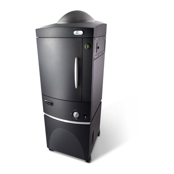
- Page 1 ® IVIS Spectrum In Vivo and In Vitro 3D Optical Imaging Bioluminescence and Fluorescence Spectral Unmixing Transmission and Reflectance Imaging Hardware Manual March 2012...
- Page 2 © 2007-2012 Caliper Corporation. All rights reserved. 121450_Rev01 Caliper LIfe Sciences 68 Elm Street Hopkinton, MA 01748 Main Phone: 1.508.435.9500 Fax: 1.508.435.3439 E-mail: tech.support@caliperls.com www.caliperls.com Discovery in the Living Organism, IVIS Imaging System and Living Image are either registered trademarks or trademarks of Xenogen Corporation.
-
Page 3: Table Of Contents
IVIS Spectrum Hardware Manual ® Contents 1 Welcome ......... . . 1 1.1 About the IVIS Spectrum Imaging System . - Page 4 Contents 5.6 Weights & Dimensions ........23 ®...
- Page 5 IVIS Spectrum Hardware Manual ® 9.4 Moving the System ........55 10 Servicing &...
- Page 6 Contents...
-
Page 7: Welcome
IVIS Spectrum Hardware Manual ® Welcome About the IVIS Spectrum Imaging System ....1 IVIS Imaging Systems Technology Support ....3 1.1 About the IVIS Spectrum Imaging System The IVIS Spectrum Imaging System is a high-sensitivity, low noise, in vivo... - Page 8 1. Welcome camera XGI-8 Gas Anesthesia System High resolution monitor Imaging chamber Acquisition computer XWS-260 Workstation Compartment that contains the ThermoCube chiller unit and camera power supply Figure 1.1 IVIS ® Spectrum Imaging System The IVIS Spectrum is an integrated imaging system that includes a: •...
-
Page 9: Ivis Imaging Systems Technology Support
IVIS Spectrum Hardware Manual ® 1.2 IVIS Imaging Systems Technology Support For technical support, please contact Caliper at: Telephone 1.877.522.2447 (US) 1.508.435.9500 E-mail tech.support@caliperls.com 1.508.435.3439 Caliper Life Sciences Mail US Corporate Headquarters 68 Elm Street Hopkinton, MA 01748... - Page 10 1. Welcome [This page intentionally blank.]...
-
Page 11: Important Safety Instructions
IVIS Spectrum Hardware Manual ® Important Safety Instructions Definitions ........5 Instrument Labels . -
Page 12: Instrument Labels
2. Important Safety Instructions 2.2 Instrument Labels Pay careful attention to the labels on the instrument. Label Description The Caliper IVIS Spectrum Imaging Instrument contains a Class 3R Laser module. ® The instrument itself is classified as a Class 1 device because the user is safely protected from the laser beam. -
Page 13: Laser Safety
IVIS Spectrum Hardware Manual ® 2.4 Laser Safety The IVIS Spectrum is equipped with Class 3R laser (532 nm (green) laser source, 5 mW maximum continuous (CW), which is suitably embedded and limited in power to less than 1mW where accessible in the imaging compartment behind the front door. -
Page 14: Power Considerations
2. Important Safety Instructions Water & Moisture VOLTAGE VOLTAGE! Do not use this product near water (for example, near a sink or wet room) due to risk of electric shock, electrical damage, and/or failure. The IVIS Spectrum requires a minimum of 100 square feet (9 square meters) Laboratory Space &... -
Page 15: Cleaning Or Moving The System Components
IVIS Spectrum Hardware Manual ® A separate surge protector is provided for the computer and other accessory equipment. Facilities should be adequately wired according to local building codes. If the IVIS Imaging System experiences a loss of supply power, turn off the Power Outages power switch for all components and do not restart the system until reliable power has been restored. -
Page 16: Servicing
2. Important Safety Instructions 2.10 Servicing Refer all servicing to IVIS Imaging Systems Technology Support. If the product is damaged and requires service, unplug the product from the outlet and contact technical support. Servicing by anyone other than those authorized by Caliper voids any warranty covering this product. -
Page 17: Warnings
IVIS Spectrum Hardware Manual ® Warnings Electrical Safety ......Burn Hazard & Eye Safety ......Mechanical Safety . -
Page 18: Burn Hazard & Eye Safety
3. Warnings 3.2 Burn Hazard & Eye Safety Laser The IVIS Spectrum Imaging Instrument contains an embedded Class 3R Laser module: 532 nm (visible green) laser source, 5 mW maximum continuous (CW). The instrument itself is classified as a Class 1 device because the user is safely protected from the laser beam. - Page 19 IVIS Spectrum Hardware Manual ® Figure 3.2 IVIS Spectrum, imaging chamber door CAUTION CAUTION! DO NOT defeat any of the safety interlocks. Do not place anything under the imaging platform. The imaging platform cannot be moved unless the door is closed and locked. If the platform moves when the door is unlocked, shut down the system and contact IVIS Imaging Systems Technology Support.
- Page 20 3. Warnings Filter wheel panel Figure 3.3 Filter wheel removable panel The laser beam is directed into the imaging chamber through an opening at the top of the chamber. Never place any object, tool, or fingers into this opening, otherwise damage to the galvanometer will result. WARNING WARNING! DO NOT look directly into this opening when the laser is operating.
-
Page 21: Chemical & Biological Safety
IVIS Spectrum Hardware Manual ® 3.4 Chemical & Biological Safety Normal operation may involve the use of test samples that are pathogenic, toxic, or radioactive. It is your responsibility to ensure that all necessary safety precautions are taken before such materials are used. Dispose of all waste materials according to appropriate environmental health and safety guidelines. - Page 22 3. Warnings [This page intentionally blank.]...
-
Page 23: Legal Notices
IVIS Spectrum Hardware Manual ® Legal Notices Limited Warranty ......Patents ........Trademarks . -
Page 24: Patents
4. Legal Notices OR ANY ASSOCIATED EQUIPMENT, COST OF CAPITAL, COST OF ANY SUBSTITUTE EQUIPMENT OR FACILITIES, DOWNTIME, THE CLAIMS OF ANY THIRD PARTIES, INCLUDING CUSTOMERS, AND INJURY TO PROPERTY, RESULTING FROM THE PURCHASE OR USE OF THE SYSTEM OR ARISING FROM BREACH OF THE WARRANTY, BREACH OF CONTRACT, NEGLIGENCE, STRICT TORT, OR ANY OTHER LEGAL OR EQUITABLE THEORY, EVEN IF CALIPER KNEW OF THE... - Page 25 IVIS Spectrum Hardware Manual ® Corporation in the United States and/or other countries. Adobe and Illustrator are either registered trademarks or trademarks of Adobe Systems Incorporated in the United States and/or other countries. Intel is a registered trademark of Intel Corporation.
- Page 26 4. Legal Notices [This page intentionally left blank.]...
-
Page 27: Specifications
IVIS Spectrum Hardware Manual ® Specifications Electrical Power Requirements ..... CCD Camera ....... . Optics . -
Page 28: Optics
5. Specifications 5.3 Optics Optical Component Specification Lens f/stop f/1- f/8 Field of View (FOV) 3.9, 6.5, 13, 19.5, and 26 cm Resolution >60 μm (FOV = 3.9, f/1) Scanning Laser <1 mW at 532 nm 5.4 Fluorescence Imaging Components Fluorescence Imaging Specification Component... -
Page 29: Weights & Dimensions
IVIS Spectrum Hardware Manual ® 5.6 Weights & Dimensions Item Specification Weight 275 kg (600 lbs) Depth 77 cm (30 inches) Width 65 cm (25.5 inches) Height 211 cm (83 inches) Imaging Chamber Internal 51 x 51 x 66 cm (D x W x H) Dimensions... - Page 30 5. Specifications [This page intentionally blank.]...
-
Page 31: Ivis ® Spectrum Components
IVIS Spectrum Hardware Manual ® IVIS Spectrum Components ® CCD Camera ....... . ThermoCube Chiller Unit . -
Page 32: Ccd Camera
6. IVIS ® Spectrum Components CCD camera Integrated fluorescent imaging features: Emission filter wheel Custom lens, 11-position filter wheel assembly, Scanning laser laser light alignment assembly Excitation filter wheel Imaging chamber Gas anesthesia manifold Heated platform Top illumination light source Bottom illumination light source Compartment that... -
Page 33: Imaging Chamber
IVIS Spectrum Hardware Manual ® Figure 6.2 ThermoCube chiller unit 6.3 Imaging Chamber The imaging chamber is a highly specialized device consisting of the (Figure 6.3) imaging chamber housing, a heated, moveable platform, an auto focusing lens system with f/stop control, and synchronized filter wheels that control the spectral content of the luminescent or fluorescent images. -
Page 34: Optical Components
6. IVIS ® Spectrum Components Door locking hardware Figure 6.3 IVIS Spectrum, imaging chamber ® 6.4 Optical Components The IVIS Spectrum is equipped with a rotating lens carousel that provides Imaging System/Lenses ® demagnification of 1.5X, 2.5X, 5X, and 8.8X power .The filter wheel (Figure 6.4) ®... -
Page 35: Specimen Warming System
IVIS Spectrum Hardware Manual ® There are two 11-position filter wheels. Filter settings are selected by software Emission & Excitation control. For more details on how to access the filter wheels and change filters, Filter Wheels page Figure 6.5 Filter wheel For fluorescence studies, the IVIS Spectrum Imaging System can illuminate a ®... -
Page 36: Laser/Galvanometer System
6. IVIS ® Spectrum Components 6.6 Laser/Galvanometer System The laser/galvanometer system comprises a Class 3R laser (532 nm (visible green) laser source, 5 mW maximum continuous (CW). The laser beam is directed into the imaging chamber by two computer-controlled mirrors. WARNING WARNING! A laser beam can be harmful to the eyes. -
Page 37: Acquisition Computer
IVIS Spectrum Hardware Manual ® Ventilation openings Ventilation openings Figure 6.7 IVIS Spectrum, back view 6.9 Acquisition Computer The system includes a Windows -based personal computer. The Living Image ® ® software as well as Microsoft Office software is installed on the computer. The Living Image software controls the IVIS Spectrum, and displays and analyzes the image data. - Page 38 6. IVIS ® Spectrum Components Table 6.1 Connector pin usage Pin Number Function 12 and 13 Use these pins to monitor the skin or rectal temperature of the animal. The use of a copper-constantan thermocouple is recommended. These pins may also be used to connect to the THM 100 ECG monitor (Indus Instruments).
-
Page 39: High Reflectance Hemisphere
IVIS Spectrum Hardware Manual ® 6.11 High Reflectance Hemisphere You can special order a high reflectance hemisphere that is used to check for light contamination in the imaging chamber (Figure 6.10) The hemisphere does not emit any photons when it is imaged in a light-tight and contaminant-free imaging chamber. - Page 40 6. IVIS ® Spectrum Components [This page intentionally blank.]...
-
Page 41: Operating The Ivis ® Spectrum
IVIS Spectrum Hardware Manual ® Operating the IVIS Spectrum ® Restarting the System ......Gas Plumbing ....... Door Operation . - Page 42 7. Operating the IVIS ® Spectrum Status light Bottom illumination input optics Gas valve Standby toggle switch Figure 7.1 IVIS Spectrum Table 7.1 IVIS Spectrum status light modes Status Light Is... Indicates... Blue The system is in standby mode. Blue and blinking The CCD camera cooling system is disabled due to a power interruption.
-
Page 43: Gas Plumbing
IVIS Spectrum Hardware Manual ® 5. In the Living Image software, click Initialize IVIS system in the IVIS System Control panel (Figure 7.2) — The status light is red. 6. Wait until the camera has cooled to operating temperature (requires about ten minutes). - Page 44 7. Operating the IVIS ® Spectrum CAUTION CAUTION! Caliper recommends using the XGI-8 Gas Anesthesia System when imaging small animals. This system supplies a controlled (Figure 7.3) amount of isoflurane to the imaging chamber and continuously reduces the build-up of isoflurane in the chamber. If you want to use a gas other than the recommended isoflurane/oxygen gas mixture or pure air, contact IVIS Imaging Systems Technology Support.
-
Page 45: Door Operation
IVIS Spectrum Hardware Manual ® The mouse anesthesia manifold (part no. 117706) with transparent nose cones is provided with the IVIS Spectrum. The manifold has capacity for up to five ® mice and has a low profile (height) for operation with the system. NOTICE The IVIS Imaging System 100 Series and the XGI-8 Gas Anesthesia System are equipped with a different five-station manifold (PN 118274) that is taller... - Page 46 7. Operating the IVIS ® Spectrum To display the alignment grid, choose Alignment Grid On. Figure 7.4 IVIS System Control panel 2. Open the imaging chamber door to see the alignment grid projected by the laser/galvanometer on the imaging platform (Figure 7.5) —...
-
Page 47: Fluorescent Imaging
IVIS Spectrum Hardware Manual ® 7.5 Fluorescent Imaging The IVIS Spectrum has both bioluminescent and fluorescent imaging ® capabilities. To change from bioluminescent to fluorescent operation, select fluorescence mode in the IVIS System Control panel and select an appropriate excitation and emission filter (Figure 7.6) Choose luminescent or... -
Page 48: Imaging Basics
7. Operating the IVIS ® Spectrum In fluorescence mode, the excitation filter is automatically selected based on the Selecting an Excitation wavelength of the emission (imaging) filter selected from the IVIS System Filter Control panel. However, you can override the automatic selection in the IVIS System Control panel. - Page 49 IVIS Spectrum Hardware Manual ® 5. Turn off the main circuit breaker switch located on the rear of the IVIS Spectrum and disconnect the power cord from the wall socket. 6. Cover the gas inlet and outlet ports with masking tape to prevent entry of dust.
- Page 50 7. Operating the IVIS ® Spectrum [This page intentionally blank.]...
-
Page 51: Troubleshooting
IVIS Spectrum Hardware Manual ® Troubleshooting Measured Temperature Does Not Equal the Demand Temperature . 45 Photographic Image Is Unacceptable ....Luminescent Image Is Unacceptable ....No Image Is Produced . -
Page 52: Photographic Image Is Unacceptable
8. Troubleshooting 8.2 Photographic Image Is Unacceptable Default camera controls are programmed during the initialization of the Living Image software. Changes to these settings can greatly affect the photographic ® image. Check that the exposure time, f/stop and binning levels are set to the default conditions. -
Page 53: Luminescent Image Is Unacceptable
IVIS Spectrum Hardware Manual ® 8.3 Luminescent Image Is Unacceptable Binning, f/stop, and exposure time affect the appearance of a luminescent image. Please refer to the Living Image Software Manual for instructions on ® setting binning, exposure time, and f/stop values. In order to function properly and reduce camera noise, the CCD camera must be cooled to the demand temperature before acquiring an image. -
Page 54: No Image Is Produced
8. Troubleshooting 8.4 No Image Is Produced If no image is produced, there may be an error in the Living Image software, a problem with the physical connections to the camera, or a hardware failure. 1. Close the Living Image software and restart the computer. - Page 55 IVIS Spectrum Hardware Manual ® 3. Turn off the rear panel circuit breaker switch. Front panel Back panel Toggle switch Figure 8.4 IVIS Spectrum, front and back panels 4. Check the connections between the computer and the rear panel of the IVIS Spectrum.
-
Page 56: Accessing The Area Under The Imaging Platform
8. Troubleshooting 8.6 Accessing the Area Under the Imaging Platform During normal operation, the imaging platform always returns to the loading position before the door can be opened. This helps ensure user safety and convenience when loading subjects. Occasionally you may need access to the area beneath the platform for cleaning or to retrieve a subject. -
Page 57: Care & Maintenance
IVIS Spectrum Hardware Manual ® Care & Maintenance Cleaning the IVIS Spectrum ..... . . Cleaning the Lens Protection Window ....Changing the Emission Filters Used in Fluorescence Imaging . -
Page 58: Cleaning The Lens Protection Window
9. Care & Maintenance Table 9.1 Acceptable cleaning solutions for the IVIS ® Spectrum imaging chamber Cleaning Solution Manufacturer Cidexplus Solution (3.4% glutaraldehyde) Johnson & Johnson Medical ® 70% methyl alcohol/30% deionized water solution 70% ethyl alcohol/30% deionized water solution Sporicidin Sterilizing Solution (1.56% Sporicidin International... -
Page 59: Changing The Emission Filters Used In Fluorescence Imaging
IVIS Spectrum Hardware Manual ® 4. Take an image to confirm that the image quality is restored. 9.3 Changing the Emission Filters Used in Fluorescence Imaging The following steps explain how to change one or more of the optional emission filters used for fluorescence imaging in the IVIS Spectrum. - Page 60 9. Care & Maintenance 7. To clean a filter, use a Dust-Off compressed gas duster to apply an air ® stream at an angle to the filter surface, otherwise dust particles could be driven into the filter coating. NOTICE Do not blow air onto a filter in the filter wheel as dust could be spread to other optical components.
-
Page 61: Moving The System
IVIS Spectrum Hardware Manual ® 9.4 Moving the System It may be necessary to remove the plastic camera dome when you move the Removing the Dome IVIS Spectrum though a doorway or other low overhang. ® To remove the dome, wrap a flat blade screw driver with a thin cloth or ■... - Page 62 9. Care & Maintenance — The status light is red. The status light turns green when the system is initialized. Wait until the camera has cooled to the demand temperature before you begin an imaging session (about ten minutes).
-
Page 63: Servicing & Maintaining The Thermocube Chiller Unit
IVIS Spectrum Hardware Manual ® Servicing & Maintaining the ThermoCube Chiller Unit Required Tools ......Turning Off Electric Power to the Main Console . -
Page 64: Removing The Console Rear Panel
10. Servicing & Maintaining the ThermoCube Chiller Unit Figure 10.1 Lower rear panel Note that the power cord has been removed from the console. 10.3 Removing the Console Rear Panel 1. Use a 3/32" hex head wrench to remove the screws that secure the bottom rear (fan) panel (Figure 10.2) 2. -
Page 65: Sliding The Tray Out
IVIS Spectrum Hardware Manual ® 10.4 Sliding the Tray Out The ThermoCube unit sits on a tray that must be pulled out to access the unit. 1. Use the ¼" hex head (Allen) wrench to loosen and remove the bolt that secures the tray under the ThermoCube unit to the console (Figure 10.3) Figure 10.3 Loosen the tray locking bolt... -
Page 66: Filling The Thermocube Unit
10. Servicing & Maintaining the ThermoCube Chiller Unit 10.5 Filling the ThermoCube Unit 1. If additional coolant is required, wrap a piece of cloth or a paper towel around the neck of the tank to absorb accidental spills (Figure 10.5) 2. -
Page 67: Reassembling The System
IVIS Spectrum Hardware Manual ® 10.6 Reassembling the System 1. Replace the cap on the ThermoCube unit. Make sure that the cap is fully tightened to prevent rapid coolant evaporation. 2. Slide the tray back into the console while you hold the cables and hoses out of the way to prevent snagging. - Page 68 10. Servicing & Maintaining the ThermoCube Chiller Unit [This page intentionally blank.]...
-
Page 69: Appendix A Spare Parts List
IVIS Spectrum Hardware Manual ® Appendix A Spare Parts List Description Caliper Part Number Mouse Inhalation Nose Cone 117150 Low Profile, 5 Station Manifold 117706 XRH-1 High-Reflectance Hemisphere with container 118937 Black Paper, Swarthmore, Artagain. 9x12”, 24 sheet pad 117837 Low Fluorescence Imaging Mat, 11.6”... - Page 70 A. Spare Parts List [This page intentionally blank.]...
- Page 71 IVIS Spectrum Hardware Manual ® Index emission filter selecting 41 accessory cable 31 emission filter wheel 29 back connector 32 emission filters stage connector 32 changing 53–54 anesthesia delivery system 38 environmental considerations 7 anesthesia manifold 39 heat 7 array plate 41 location of system 7 space and ventilation 8 water and moisture 8...
- Page 72 Index gas plumbing 37 imaging platform patents 18 accessing space below 50 photographic image unacceptable 46 lock down bar 50 pinch hazard label 6 warming system 29 power cord 8 imaging system power line surges 8 proper location 7 power outages 9 information on manual instructions 6 power overloading 9 instrument labels...
- Page 73 IVIS Spectrum Hardware Manual ® system cleaning 9 moving 9, 55–56 servicing 10 shut down 42–43 temperature measured unequal to demand 45 ThermoCube servicing 57–61 ThermoCube chiller unit 26 trademarks 18 transillumination 41 troubleshooting camera noise 47 light contamination 47 measured temperature does not equal demand temperature 45 no image produced 48...
- Page 74 Index...
Need help?
Do you have a question about the Caliper IVIS Spectrum and is the answer not in the manual?
Questions and answers