Table of Contents
Advertisement
Quick Links
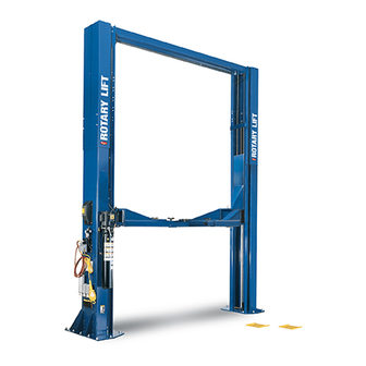
Sprinter SPO15 (3A0 Lifts) Capacity 11,000 lbs.
Standard SPO15 (300 Series Lifts) Capacity 15,000 lbs.
Standard SPO18 (300 Series Lifts) Capacity 18,000 lbs.
© November 2005 by Rotary Lift. All rights reserved.
SPO15, SPO18
LP20293
N
N
S
S
T
T
A
A
L
L
L
L
A
A
T
T
O
O
N
N
N
N
S
S
T
T
R
R
U
U
C
C
T
T
O
O
N
N
S
S
IN20379
CO6363.1 Rev. A 11/22/2005
I
I
I
I
I
I
I
I
Advertisement
Table of Contents

Related Manuals for Rotary Sprinter SPO15


Summary of Contents for Rotary Sprinter SPO15
- Page 1 SPO15, SPO18 Sprinter SPO15 (3A0 Lifts) Capacity 11,000 lbs. Standard SPO15 (300 Series Lifts) Capacity 15,000 lbs. Standard SPO18 (300 Series Lifts) Capacity 18,000 lbs. LP20293 IN20379 © November 2005 by Rotary Lift. All rights reserved. CO6363.1 Rev. A 11/22/2005...
- Page 2 Wheel Spotting Dishes 7''– 6" Min. To Nearest Obstruction " 15'– 0" Min. To Front Nearest Obstruction 34" 6" Power Unit to Passenger Side 28" (18) " Anchors " Lift Alignment Notches 15'– 0" Min. To Nearest Obstruction Rear 12' - 11" Fig.
- Page 3 Anchor 2-1/4" 3-1/4" Shims 4-1/4" 4-1/4" Flat (1/2" Max.) Washer Clean hole. Drill holes using Tighten nut with 3/4" carbide Run nut down just Fig. 3 Torque wrench tipped maso- below impact section to 150 ft.-lbs. nary drill bit per of bolt.
- Page 4 6. Mount switch assembly towards power unit column Attach overhead to extension using 3/8"-16NC x 3/4" as shown, Fig. 4, using (2) 1/4"-20NC x 3/4" lg. HHCS, Flanged HHCS and 3/8"-16NC Flanged Locknuts. Use (1) 3/8" Star Lockwasher on Power Unit Side. nuts and Star Washers.
- Page 5 Hose Routes Diagonally Across Overhead Fig. 7b Hose runs through holes in Use (4) 5/16”-18NC x 1-1/2” HHCS And Nuts extensions, then through holes in overhead. Hose runs down approach side to Push nuts hold bolts to brackets cylinder on left column. CAPACITY 15,000 LBS.
- Page 6 Upper Cable Tie Off Upper Cable Tie Off 3/4" Nylon Insert Locknut 3/4" Nylon Insert Locknut For 16'-6" height with 472" long cable or for 14'-6" height with For 15'-6" height lift with 472" cable or for 13'-6" height lift with 424"...
- Page 7 11. Locking Latch & Air Cylinders: A) To install cylinder, first slip dampening spacer over rod with rod in retracted position as shown below, Fig. 12. B) Put locknut on threaded shaft and run it down to the dampening spacer. C) Let rod extend and thread locknut down 1-1/2 more turns.
- Page 8 Single Phase Power Unit 12. Electrical: Have a certified electrician run appropriate power supply to motor, Fig. 21 & 22. Size wire for 20 amp circuit. See Motor Operating Data Table. MOTOR OPERATING DATA TABLE - SINGLE PHASE CAUTION Never operate the motor on line voltage less LINE VOLTAGE RUNNING MOTOR VOLTAGE RANGE than 208V.
- Page 9 Three Phase Power Unit MOTOR OPERATING DATA TABLE - THREE PHASE LINE VOLTAGE RUNNING MOTOR VOLTAGE RANGE 208-240V 50/60Hz. 197-253V 400V 50Hz. 360-440V 440-480V 50/60Hz. 396V-528V 575V 60Hz. 518V-632V NOTES: 1. Unit not suitable for use in unusual conditions. Contact Ro- tary for moisture and dust environment duty unit.
- Page 10 Arm Clevis Arm Pin "TOP" will be marked on top side of restraint gear Cotter Pin Rounded Edge Up Restraint Gear Fig. 20 (12) 3/8-16NC x 1-1/2" lg. HHCS (12) 3/8" Spring Lockwashers Fig. 18 15. Arm Restraints & Superstructure: Before install- After installing arm pin, torque the three Restraint ing arms, install arm Restraint Gears as follows: Install Gear bolts to 30-34 Ft.
- Page 11 21. Adapter Rack: Install adapter rack, Fig. 24. Place 17. Door Bumper Installation: 1) Press bumpers on column edge and carriage, Fig. 22. extension in racks. Note: Door Bumpers may need to be installed in different areas depending upon type(s) of vehicles used. The above installation is the most recommended.
- Page 12 Latin America / Caribbean: +54.3488.431.608 ® © Rotary , Printed in U.S.A., All Rights Middle East / Northern Africa: +49.771.9233.0 Reserved. Unless otherwise indicated, ROTARY, DOVER and all other trademarks are property of Dover Corporation and its affiliates.
Need help?
Do you have a question about the Sprinter SPO15 and is the answer not in the manual?
Questions and answers