Advertisement
Quick Links
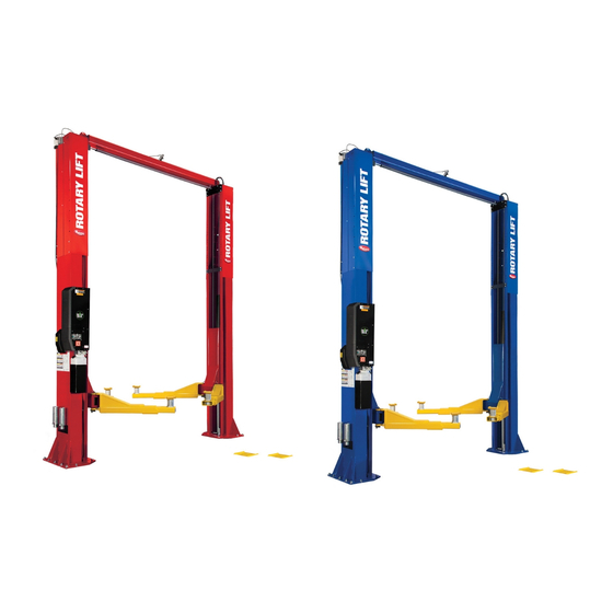
SPO16 Capacity 16,000 lbs. (7,258 kg.) / 4,000 lbs. (1,814 kg.) per Arm
SPO20 Capacity 20,000 lbs. (9,072 kg.) / 5,000 lbs. (2,268 kg.) per Arm
© May 2019 by Vehicle Service Group.
All rights reserved.
SPO16, SPO20
OPERATING CONDITIONS
Lift is not intended for outdoor use
and has an operating ambient temperature
range of
41°-104°F (5°-40°C)
LP20650
CO10949
I
I
N
N
S
S
T
T
A
A
L
L
L
L
A
A
T
T
I
I
O
O
N
N
I
I
N
N
S
S
T
T
R
R
U
U
C
C
T
T
I
I
O
O
N
N
S
S
IN20825
Rev. H 5/22/2019
Advertisement

Related Manuals for Rotary SPO16


Summary of Contents for Rotary SPO16
- Page 1 SPO16, SPO20 SPO16 Capacity 16,000 lbs. (7,258 kg.) / 4,000 lbs. (1,814 kg.) per Arm SPO20 Capacity 20,000 lbs. (9,072 kg.) / 5,000 lbs. (2,268 kg.) per Arm OPERATING CONDITIONS Lift is not intended for outdoor use and has an operating ambient temperature range of 41°-104°F (5°-40°C)
- Page 2 Lift Location: Use architects plan when available to locate Lift Setting: Position columns in bay using dimensions lift. Fig. 1 shows dimensions of a typical bay layout. shown in Fig.1. Place column with power unit mounting bracket on vehicle passenger side of lift. Both column base plate backs must be square on center line of lift.
- Page 3 Lift Height: See Fig. 2 for overall lift height of each specific Install Column Extensions to columns using (4) 3/8"-16NC x lift model. Add 1” min. to overall height to lowest obstruction. 1/2" Lg. Flanged HHCS and (3) 1/4"-20NC x 5/8" Lg. Flanged HHCS with (3) 1/4"-20NC Lock Nut, Fig.
- Page 4 5. Attach Overhead Bracket to column extensions using (4) 1/2"-13NC x 1-1/4" lg. Flanged HHCS and (4) 1/2"-13NC Flanged Locknut), Fig. 5. Fig. 5 (4) 1/2”-13NC Flanged Lock Nut (4) 1/2”-13NC x 1-1/4” Lg. Flanged HHCS 6. Attach overhead assembly to overhead bracket with (2) 1/2"-13NC x 1-1/4"...
- Page 5 Drill (14) 3/4" dia. holes (7 per side) in concrete floor using holes Concrete and Anchoring: in column base plate as a guide. See diagrams for hole depth, hole spacing, and edge distance requirements. CAUTION DO NOT install on asphalt or other similar unstable surfaces.
- Page 6 IMPORTANT: Using the horse shoe shims provided, shim If anchors do not tighten to 110 ft-lbs. installation torque, replace each column base until each column is plumb. If one column concrete under each column base with a 6' x 6' x 6" thick 3000 has to be elevated to match the plane of the other column, full PSI minimum concrete pad keyed under and flush with the top size base shim plates should be used (Reference Shim Kit...
- Page 7 9. Mount latch release air valve and bracket to column using (2) 5/16"-18NC x 3/8" lg. PHMS, Fig. 8. Fig. 8 (2) 5/16" x 3/8" Lg. Pan Head Screw With (2) 5/16" Ext. Tooth Lockwashers...
- Page 8 WZLOCK HHCS (3) THREADED HOLES USED FOR 5/16" x 1/2" Lg. HEX FLGD WZLOCK HHCS N567 ADAPTER PLATE 5/16"-18NC x 1-1/2" Lg. HEX FLGD WZLOCK HHCS FOR SPO16 CAPACITY 16,000 LBS. FOR SPO20 CAPACITY 20,000 LBS. 5/16"-18NC HEX FLGD WZLOCK NUT 10.
- Page 9 11. Hoses: Clean adapters and hose. Inspect all threads HOSE CLIP for damage and hose ends to be sure they are crimped. LOCATION Adapter & Hose Installation A) Install item (2) with hose clamps, on power unit column side connecting it to the cylinder (1) first. B) Install item (3) with hose clamps starting at left column cylinder (5) and working toward the right column.
- Page 10 ITEM QTY. DESCRIPTION Hose runs through holes in Hydraulic Cylinder extensions, then through Power Unit Hose holes in overhead. Overhead Hose Branch Tee Hose runs down Hose Clips(5/8") Passenger approach side to Side cylinder on left column. 5/16"-18NC x 3/8” lg. PHMS Cylinder bleeders Hose Clips(1/2") Torque values...
- Page 11 ***Longer threaded side must always be tie - off at upper tie - off (1 and 1a) ***Overhead must have matching sheave placement on both sides to be installed correctly Stance Cable Height Narrow Standard Wide (Pin hole to Pin hole 119.375) (125.375) (131.375) Upper Tie-off...
- Page 12 13. Locking Latch & Air Cylinders: H) Slide one side of lower Pivot Pin (pre-installed & fixed A) To install cylinder, first slip dampening spacer over rod in cylinder) into one half of the column Pivot Bracket. with rod in retracted position as shown below, Fig. 16. Install Pivot Bracket into column using (2) 1/4"-20NC x 3/8"...
- Page 13 Note: Cut provided tubing with sharp blade to length as required. Tubing must be cut square with no burrs. Fig. 17 5/16-18NC x 3/8" lg. PHCS To assemble air line tubing into fitting, use firm, manual pressure to push tubing into fitting until it bottoms, see below.
- Page 14 14. Electrical: Have a certified electrician run appropriate Single Phase Power Unit power supply to motor, Figs. 19 and 20. Size wire for 20 amp circuit. See Motor Operating Data Table. MOTOR OPERATING DATA TABLE - SINGLE PHASE CAUTION Never operate the motor on line voltage less LINE VOLTAGE RUNNING MOTOR VOLTAGE RANGE than 208V.
- Page 15 17. Arm Restraints & Superstructure: Install arm restraint gear over pin and into the slot in the Before installing arms, grease arm pins and holes with arm pin ensuring the side of the gear marked TOP is facing lithium grease. Slide arm onto yoke and install the arm upward.
- Page 16 After installing arm pin, torque the three Restraint Gear Release or lower pin bolts to 30-34 Ft-Lbs. Let the Gear Block down allowing to activate restraint the teeth of the Restraint Gear and Gear Block to mesh together, Fig. 24. Fig.
- Page 17 23. Adapter Rack: Install adapter rack, Fig. 27. Place 19. Door Bumper Installation: extension in racks. 1) Press bumpers on column edge and carriage, Fig. 25. Note: Door Bumpers may need to be installed in different Fig. 27 areas depending upon type(s) of vehicles used. The above installation is the most recommended.
- Page 18 SPO16 - SPO20 2-Post DC Installation Recommended Battery Specifications Normal Operation and Life High Use (15 minutes or less between lift cyles) or increase in life under normal use Battery Type Standard Lead Acid Absorbed Glass Mat (AGM) Technology Voltage...
- Page 19 B) Install included 3/8 NPT strain relief and nut to the back of the cabinet and route the FA9190-6 over head switch cable through the strain relief, Figure 30. The FA9190-6 overhead switch cable Fig. 30 is shipped attached to the grounding bolt inside the DC control cabinet.
- Page 20 D) Mount DC control cabinet by sliding slots around the power unit bracket flanges, Figure 31 and 32. Fig. 31 Fig. 32 MOUNT CABINET SO THAT SLOTS SLIDE AROUND POWER UNIT BRACKET FLANGES NOTE: SIDE PANEL NOT SHOWN MOUNT CABINET SO THAT SLOTS SLIDE AROUND POWER UNIT...
- Page 21 27. DC Control Cabinet Top Bracket: C) Mount the bracket to the side of the cabinet using the included hardware as shown in fig. 33. A) Secure top of DC control cabinet by mounting bracket to the top of the column as shown in fig. 33. D) The DC control cabinet should rest against the side of the column.
- Page 22 Fig. 34 5/16"-18NC x 1-1/2" FULL THREAD BOLT 5/16"-18NC HEX NUTS POSITION BOLT SO THAT IT SUPPORTS THE SIDE WALL OF THE ENCLOSURE DO NOT OVERTIGHTEN AND PUSH ENCLOSURE SIDE OUTWARD Fig. 35...
- Page 23 B) Fasten the two brackets to the column and DC 28. DC Control Cabinet Bottom Bracket: control as shown below, Figure 36. A) Secure bottom of DC control cabinet by mounting it to the side of the column using the included C) Re-attach the lower cover with the same brackets.
- Page 24 D) Finally, fasten the NP280 label to the front of the 29. Lowering Valve Bracket: bracket and connect the shop air supply with A) First, attach brass filter and swivel elbows to the included in-line filter to latch release air valve air valve, Figure 36a.
- Page 25 G) Fasten the “F” labeled terminal end of the FA9190- 30. DC Control Cables: 7 cable to the positive post of the bottom battery, Fig Before making electrical connections, CAUTION verify the red disconnect switch on the side panel is H) Fasten the FA9190-5 black cable to the negative in the OFF position.
- Page 26 BATTERY TERMINALS “E” FA9190-7 Fig. 37 “D” FA9190-9 “F” FA9190-7 BATTERY TERMINAL BATTERY POST (CONNECT LAST) CONNECTOR “H” FA9190-10 Fig. 37a POSITIVE MOTOR ”A” FA9190-8 TERMINAL “G” FA9190-5 NEGATIVE MOTOR TERMINAL ”A” FA9190-8 ROUTES TO POSITIVE MOTOR TERMINAL “C” FA9190-6 “B”...
- Page 27 31. Hydraulic Fittings and Flow Control: A) Attach the hydraulic fittings and flow control as shown in the single phase power unit installation, Fig. 10. Fig. 38 RE-ATTACH TOP AND BOTTOM FRONT COVERS TO THE CABINET USING INCLUDED SCREWS...
- Page 28 Fig. 39 PLUG CHARGER CABLE INTO RECEPTACLE AND ROUTE CHARGER CABLE AND OVERHEAD SWITCH CABLE TO THE TOP OF THE EXTENSION WITH OVERHEAD HOSE USING WIRE TIES...
- Page 29 32. Charger Cable & Overhead Switch Cable: 35. Electrical: Have a certified electrician run appropriate power supply to the 120 volt A) Plug the male end of the 10 foot charger cable receptacles mounted at the top of the lift. into the receptacle on the back of the DC control cabinet.
- Page 30 Fig. 40 MOUNT THRU HOLE IN EXTENSION PUNCH OUT HOLE IN RECEPTACLE BOX THAT LINES UP WITH HOLE MOUNT RECEPTACLE BOX TO POWER UNIT COLUMN IN EXTENSION WITH INCLUDED #12-24NC X 3/4" LONG PHMS, AND #12-24NC NUTS. MOUNT #12 STAR WASHERS WITH ONE MOUNTING SCREW, AS SHOWN PLUG CHARGER CABLE INTO TOP RECEIVER...
- Page 31 Notes...
- Page 32 Please return this booklet to literature package, and give to lift owner/operator. Thank You Trained Operators and Regular Maintenance Ensures Satisfactory Performance of Your Rotary Lift. Contact Your Nearest Authorized Rotary Parts Distributor for Genuine Rotary Replacement Parts. See Literature Package for Parts Breakdown.
Need help?
Do you have a question about the SPO16 and is the answer not in the manual?
Questions and answers
Witch holes do the rollers go in on the wide settings