JUMO diraTRON 104 Brief Instructions
Compact controller
Hide thumbs
Also See for diraTRON 104:
- Operating manual (104 pages) ,
- Interface description (40 pages)

Related Manuals for JUMO diraTRON 104


Summary of Contents for JUMO diraTRON 104
- Page 1 JUMO diraTRON 104/108/116/132 Compact controller Brief Instructions 70211000T97Z001K000 V1.00/EN/00688809...
-
Page 2: Safety Information
Introduction 1 Introduction Safety information General This manual contains information that must be observed in the interest of your own safety and to avoid material damage. This information is supported by symbols which are used in this manual as indicated. Please read this manual before starting up the device. -
Page 3: Intended Use
1 Introduction Intended use The device is designed for use in an industrial environment as specified in the technical data. Other uses beyond those defined are not viewed as intended uses. The device has been manufactured in compliance with applicable standards and directives as well as the applicable safety regulations. - Page 4 1 Introduction The accompanying letter for repair can be downloaded online from the manufacturer's website (use the search function if necessary). Protection against electrostatic discharge (ESD) (ESD = electrostatic discharge) To prevent damage due to ESD, electronic modules or components must be handled, packaged, and stored in an ESD-protected environment.
- Page 5 1 Introduction Identifying the device version 1.5.1 Nameplate The nameplate is affixed to the housing. Contents The nameplate contains important information. This includes: Description Designation on the Example nameplate Device type 702114/81-4356-25/214 Part no. 00123456 Serial number F-Nr. 0070033801217480006 Voltage supply AC/DC 20 to 30 V, 48 to 63 Hz Device type (Typ) Compare the specifications on the nameplate with the order.
-
Page 6: Order Details
1 Introduction 1.5.2 Order details Basic type 702110 Type 702110 (format 132: 48 x 24 mm) 1 analog input, 2 digital inputs (digital input 1, alternative to logic output), 1 relay (N/O contact), 1 logic output 0/14 V (alternative to digital input 1) incl. - Page 7 1 Introduction Voltage supply AC 110 to 240 V +10/-15 %, 48 to 63 Hz AC/DC 20 to 30 V, 48 to 63 Hz Extra codes Not used Math and logic module Structured text The language of the device texts can be adjusted (German, English, French, Spanish). The options cannot be retrofitted! Please consider options when ordering.
-
Page 8: Brief Description
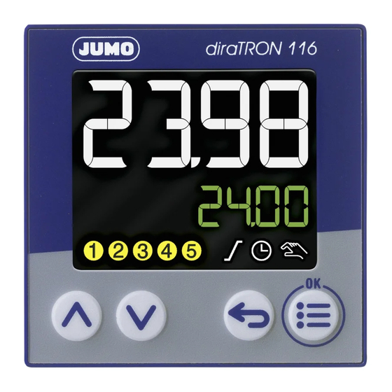
1 Introduction Brief description The controller series comprises five freely configurable, universally usable compact controllers in various DIN formats to control temperature, pressure, and other process variables. The devices are characterized by a simple, clearly structured operation supported with texts. Process values and parameters are represented by two 18-segment LCD displays. -
Page 9: Device Types
1 Introduction Device types Type 702110 (format 132) Type 702111 (format 116) Type 702113 (format 108Q) Type 702114 (format 104) Type 702112 (format 108H) Available technical documentation In addition to this quick start guide, the following documents are available as PDF files and can be down- loaded from the manufacturer's website: •... -
Page 10: Installation Instructions
Mounting 2 Mounting Installation instructions WARNING! The device is not designed for use in potentially explosive areas. Explosion hazard. Only deploy the device outside of potentially explosive areas. Mounting site The device is designed for installation in a panel cut-out within a closed switch cabinet. The front of the device and housing have different protection types (see technical data). - Page 11 2 Mounting Dimensions Type 702110 (format 132: 48 mm × 24 mm) Type 702111 (format 116: 48 mm × 48 mm) 77.9...
- Page 12 2 Mounting Type 702112 (format 108H: 48 mm × 96 mm) Type 702113 (format 108Q: 96 mm × 48 mm)
- Page 13 2 Mounting Type 702114 (format 104: 96 mm × 96 mm) Panel cut-out according to DIN IEC 61554 Type (format; front frame dimensions) Panel cut-out Minimum spacing of panel cut- (width x height) outs (for tightly packed installa- tions) Horizontal Vertical +0.6 +0.3...
-
Page 14: Din Rail Installation
2 Mounting Type 702110 (format 132) mounted on DIN rail (see accessories) 124.6 Type 702111 (format 116) mounted on DIN rail (see accessories) 114.4 DIN rail installation For devices in the formats 132 and 116, special mounting elements for mounting on a DIN rail (35 mm, according to DIN EN 60715) are available as accessories. -
Page 15: Panel Mounting
2 Mounting Panel mounting Types 702110 (format 132), 702111 (format 116) Types 702112 (format 108H), 702113 (format 108Q), 702114 (format 104) Insert the device from the front into the pan- Insert the device from the front into the pan- el cut-out and ensure that the seal is correct- el cut-out and ensure that the seal is correct- ly positioned. -
Page 16: Electrical Connection
Electrical connection 3 Electrical connection Installation notes Requirements for personnel • Work on the device must only be carried out to the extent described and, like the electrical connec- tion, only by qualified personnel. • Before plugging and unplugging connecting cables, it must be ensured that the acting person is elec- trostatically discharged (by touching grounded metallic parts, for example). -
Page 17: Connection Elements
3 Electrical connection Connection elements Type 702110 (format 132) Type 702110 (48 mm × 24 mm) Termi- Connection Termi- Connection Termi- Connection nals nals nals 1, 2 Output 1 (relay) 8, 10 Input 2 (for potential-free L1(L+), Voltage supply contact) N(L-) 3, 4 (2) = option 2: output 2 (re-... - Page 18 3 Electrical connection Types 702112 (format 108H), 702113 (format 108Q), 702114 (format 104) Type 702113 (96 mm × 48 mm) Type 702112 (48 mm × 96 mm) Type 702114 (96 mm × 96 mm) Termi- Connection Termi- Connection Termi- Connection nals nals nals...
-
Page 19: Connection Diagram
3 Electrical connection Connection diagram CAUTION! In unfavorable conditions, the temperature may exceed 60 °C at the terminals. As a result, the insulation of the cables connected at the terminals may be damaged. The affected cables must be heat-resistant up to at least 80 °C. NOTE! There is an individual connection diagram on the housing that corresponds to the ordered device ver- sion. - Page 20 3 Electrical connection 3.3.3 Analog output Version for type 702110 (format 132) Version for types 702111 to 702114 Output Symbol and termi- Output Symbol and termi- nal designation nal designation Option 2 (alternative to Option 2 (alternative to digital output 2): digital output 5): DC 0/2 ...
-
Page 21: Voltage Supply
3 Electrical connection 3.3.5 RS485 interface Version Symbol and termi- Version Symbol and termi- for type 702110 (format 132) nal designation for types 702111 to 702114 nal designation Option 1: Option 1 (alternative to digital RxD/TxD+ RxD/TxD+ output 4): RS485 interface RxD/TxD- RxD/TxD- RS485 interface... -
Page 22: Operation
Operation 4 Operation The device is configured, parametrized, and operated using the four buttons on the front. A setup pro- gram is also available for convenient configuration of the device using a PC. Some functions can only be configured with the setup program. The individual parameters for device setting are organized in different levels that can be inhibited. - Page 23 4 Operation Symbol Lights up Flashes Manual mode Manual mode is not ac- Manual mode is active tive (= automatic mode) The outputs can be manually controlled us- ing the "Up" and "Down" buttons: Increase/de- crease output level or three-step controller: Open/close actuator).
-
Page 24: Language Selection
4 Operation Language selection After switching on the device for the first time, the user can either confirm the flashing displayed lan- guage with "OK" or select another language using the "Up"/"Down" buttons and then confirm this with "OK". If, at a later point, another user is to also have the option of selecting a language, the configuration pa- rameter "Language selection active"... -
Page 25: Analog Input
Technical data 5 Technical data Analog input Thermocouples Designation Standard Measuring range Accuracy ≤ 0.25 % Fe-CuNi "L" DIN 43710 ITPS-68 -200 to +900 °C ≤ 0.25 % from -100 °C Fe-CuNi "J" IEC 60584-1 ITS-90 -210 to +1200 °C Cu-CuNi "U"... - Page 26 5 Technical data Resistance transmitter and resistor/potentiometer Designation Measuring range Accuracy Measuring current 0 to 4000 Ω ≤ 0.1 % 50 μA Resistance transmitter 0 to 400 Ω ≤ 0.1 % 500 μA Resistance/potentiometer 0 to 4000 Ω ≤ 0.1 % 50 μA The accuracy value refers to the maximum measuring range.
-
Page 27: Digital Inputs
5 Technical data Measuring Measuring Measuring Short-circuit Break (probe/ Polarity probe range underflow range overflow (probe/line) line) Voltage 2 to 10 V ++ ++ = is detected --- = is not detected (+) = is detected in certain conditions is not detected in all combinations break in measuring current path is not detected dependent on the set characteristic line Digital inputs... -
Page 28: Electrical Data
5 Technical data Interfaces USB device Connector type Micro-B (socket) Standard Low-Speed, Full-Speed Max. cable length RS485 Baud rate 9600, 19200, 38400, 115200 Data format 8/1n, 8/1e, 8/1o, 8/2n Protocol Modbus RTU as slave Display 18-segment LCD displays Digit height Upper display: Lower display: Type 702110 (format 132) -
Page 29: Environmental Influences
5 Technical data Conductor cross section Wire or stranded wire Min. 0.2 mm , max. 1.5 mm (without ferrule) Stranded wire with ferrule Without plastic collar: min. 0.2 mm , max. 1.5 mm With plastic collar: min. 0.2 mm , max. 0.75 mm Stripping length 8 mm Environmental influences... -
Page 30: Approvals/Approval Marks
5 Technical data 5.10 Approvals/approval marks Approval mark Test facility Certificate/certification Inspection basis Valid for numbers c UL us Underwriters Submitted UL 61010-1 (3. Ed.), All types Laboratories CAN/CSA- 22.2 No. 61010-1 (3. Ed.) -
Page 31: China Rohs
China RoHS 6 China RoHS... - Page 32 JUMO GmbH & Co. KG JUMO Instrument Co. Ltd. JUMO Process Control, Inc. Street address: JUMO House 6733 Myers Road Moritz-Juchheim-Straße 1 Temple Bank, Riverway East Syracuse, NY 13057, USA 36039 Fulda, Germany Harlow, Essex, CM20 2DY, UK Delivery address:...
Need help?
Do you have a question about the diraTRON 104 and is the answer not in the manual?
Questions and answers