JUMO diraTRON 104 Operating Manual
Compact controller
Hide thumbs
Also See for diraTRON 104:
- Brief instructions (33 pages) ,
- Interface description (40 pages)

Related Manuals for JUMO diraTRON 104


Summary of Contents for JUMO diraTRON 104
- Page 1 JUMO diraTRON 104/108/116/132 Compact controller Operating Manual 70211000T90Z001K000 V3.00/EN/00688648...
-
Page 3: Table Of Contents
Contents Contents Introduction ........... . 7 Safety information . - Page 4 Contents Level inhibit ..............34 User level .
- Page 5 Contents Math/Logic ..............80 Service .
- Page 6 Contents...
-
Page 7: Introduction
Introduction 1 Introduction Safety information General This manual contains information that must be observed in the interest of your own safety and to avoid material damage. This information is supported by symbols which are used in this manual as indicated. Please read this manual before starting up the device. -
Page 8: Intended Use
1 Introduction Intended use The device is designed for use in an industrial environment as specified in the technical data. Other uses beyond those defined are not viewed as intended uses. The device has been manufactured in compliance with applicable standards and directives as well as the applicable safety regulations. -
Page 9: Disposal
1 Introduction The accompanying letter for repair can be downloaded online from the manufacturer's website (use the search function if necessary). Protection against electrostatic discharge (ESD) (ESD = electrostatic discharge) To prevent damage due to ESD, electronic modules or components must be handled, packaged, and stored in an ESD-protected environment. -
Page 10: Identifying The Device Version
1 Introduction Identifying the device version 1.5.1 Nameplate The nameplate is affixed to the housing. Contents The nameplate contains important information. This includes: Description Designation on the Example nameplate Device type 702114/81-4356-25/214 Part no. 00123456 Serial number F-Nr. 0070033801217480006 Voltage supply AC/DC 20 to 30 V, 48 to 63 Hz Device type (Typ) Compare the specifications on the nameplate with the order. -
Page 11: Order Details
1 Introduction 1.5.2 Order details Basic type 702110 Type 702110 (format 132: 48 x 24 mm) 1 analog input, 2 digital inputs (digital input 1, alternative to logic output), 1 relay (N/O contact), 1 logic output 0/14 V (alternative to digital input 1) incl. -
Page 12: Scope Of Delivery
1 Introduction Voltage supply AC 110 to 240 V +10/-15 %, 48 to 63 Hz AC/DC 20 to 30 V, 48 to 63 Hz Extra codes Without extra code Math and logic module Structured text The language of the device texts can be adjusted (German, English, French, Spanish). The options cannot be retrofitted! Please consider options when ordering. -
Page 13: Brief Description
1 Introduction Brief description The controller series comprises five freely configurable, universally usable compact controllers in various DIN formats to control temperature, pressure, and other process variables. The devices are characterized by a simple, clearly structured operation supported with texts. Process values and parameters are represented by two 18-segment LCD displays. -
Page 14: Device Types
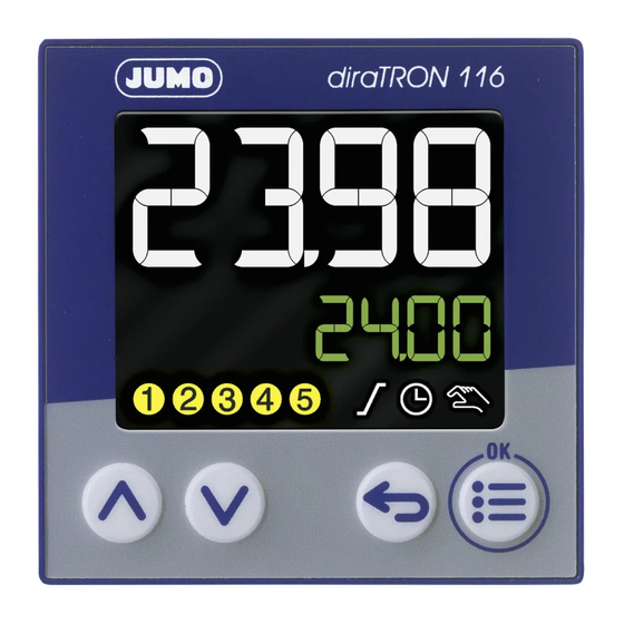
1 Introduction Device types Type 702110 (format 132) Type 702111 (format 116) Type 702113 (format 108Q) Type 702114 (format 104) Type 702112 (format 108H) -
Page 15: Mounting
Mounting 2 Mounting Installation instructions WARNING! The device is not designed for use in potentially explosive areas. Explosion hazard. Only deploy the device outside of potentially explosive areas. Mounting site The device is designed for installation in a panel cut-out within a closed switch cabinet. The front of the device and housing have different protection types (see technical data). -
Page 16: Dimensions
2 Mounting Dimensions Type 702110 (format 132: 48 mm × 24 mm) Type 702111 (format 116: 48 mm × 48 mm) 77.9... - Page 17 2 Mounting Type 702112 (format 108H: 48 mm × 96 mm) Type 702113 (format 108Q: 96 mm × 48 mm)
- Page 18 2 Mounting Type 702114 (format 104: 96 mm × 96 mm) Panel cut-out according to DIN IEC 61554 Type (format; front frame dimensions) Panel cut-out Minimum spacing of panel cut- (width x height) outs (for tightly packed installa- tions) Horizontal Vertical +0.6 +0.3...
- Page 19 2 Mounting Type 702110 (format 132) mounted on DIN rail (see accessories) 124.6 Type 702111 (format 116) mounted on DIN rail (see accessories) 114.4...
-
Page 20: Din Rail Installation
2 Mounting DIN rail installation For devices in the formats 132 and 116, special mounting elements for mounting on a DIN rail (35 mm, according to DIN EN 60715) are available as accessories. This involves a base plate attached to the DIN rail and a device holder (see depictions in the section "Dimensions"). -
Page 21: Panel Mounting
2 Mounting Panel mounting Types 702110 (format 132), 702111 (format 116) Types 702112 (format 108H), 702113 (format 108Q), 702114 (format 104) Insert the device from the front into the pan- Insert the device from the front into the pan- el cut-out and ensure that the seal is correct- el cut-out and ensure that the seal is correct- ly positioned. - Page 22 2 Mounting...
-
Page 23: Electrical Connection
Electrical connection 3 Electrical connection Installation notes Requirements for personnel • Work on the device must only be carried out to the extent described and, like the electrical connec- tion, only by qualified personnel. • Before plugging and unplugging connecting cables, it must be ensured that the acting person is elec- trostatically discharged (by touching grounded metallic parts, for example). -
Page 24: Connection Elements
3 Electrical connection Connection elements Type 702110 (format 132) Type 702110 (48 mm × 24 mm) Termi- Connection Termi- Connection Termi- Connection nals nals nals 1, 2 Output 1 (relay) 8, 10 Input 2 (for potential-free L1(L+), Voltage supply contact) N(L-) 3, 4 (2) = option 2: output 2 (re-... - Page 25 3 Electrical connection Types 702112 (format 108H), 702113 (format 108Q), 702114 (format 104) Type 702113 (96 mm × 48 mm) Type 702112 (48 mm × 96 mm) Type 702114 (96 mm × 96 mm) Termi- Connection Termi- Connection Termi- Connection nals nals nals...
-
Page 26: Connection Diagram
3 Electrical connection Connection diagram CAUTION! In unfavorable conditions, the temperature may exceed 60 °C at the terminals. As a result, the insulation of the cables connected at the terminals may be damaged. The affected cables must be heat-resistant up to at least 80 °C. NOTE! There is an individual connection diagram on the housing that corresponds to the ordered device ver- sion. -
Page 27: Analog Output
3 Electrical connection 3.3.3 Analog output Version for type 702110 (format 132) Version for types 702111 to 702114 Output Symbol and termi- Output Symbol and termi- nal designation nal designation Option 2 (alternative to Option 2 (alternative to digital output 2): digital output 5): DC 0/2 ... -
Page 28: Rs485 Interface
3 Electrical connection 3.3.5 RS485 interface Version Symbol and termi- Version Symbol and termi- for type 702110 (format 132) nal designation for types 702111 to 702114 nal designation Option 1: Option 1 (alternative to digital RxD/TxD+ RxD/TxD+ output 4): RS485 interface RxD/TxD- RxD/TxD- RS485 interface... -
Page 29: Operation
Operation 4 Operation The device is configured, parametrized, and operated using the four buttons on the front. A setup pro- gram is also available for convenient configuration of the device using a PC. Some functions can only be configured with the setup program. The individual parameters for device setting are organized in different levels that can be inhibited. - Page 30 4 Operation Symbol Lights up Flashes Manual mode Manual mode is not ac- Manual mode is active tive (= automatic mode) The outputs can be manually controlled us- ing the "Up" and "Down" buttons: Increase/de- crease output level or three-step controller: Open/close actuator).
-
Page 31: Language Selection
4 Operation Language selection After switching on the device for the first time, the user can either confirm the flashing displayed lan- guage with "OK" or select another language using the "Up"/"Down" buttons and then confirm this with "OK". If, at a later point, another user is to also have the option of selecting a language, the configuration pa- rameter "Language selection active"... -
Page 32: Manual Mode
4 Operation Manual mode After switching to manual mode – for all controller types except the three-step controller – either the cur- rent output level or a specific, adjustable output level is displayed and output (configurable). The "Up" and "Down" buttons can be used to change the output level. For the three-step controller, the actuator gradually opens each time the "Up"... - Page 33 4 Operation Operating level Sub-menu 1 Sub-menu 2 User level Program editor Section 1 (only for program controller) Section 24 Parameterization Parameter block 1 Parameter block 2 Configuration System data Display/operation Analog input Digital inputs Analog output (if available) Digital outputs Controller Controller configuration Controller input...
-
Page 34: Level Inhibit
4 Operation Level inhibit Access to the individual levels can be inhibited. Press and hold the "Menu/OK" and "Down" buttons at the same time for longer than 5 seconds to set the level inhibit. The corresponding degree of inhibition can be selected using the "Up" and "Down" buttons and con- firmed using the "Menu/OK"... -
Page 35: Service
4 Operation ST code version Version of the "ST code" extra code Hardware version Device hardware version 4.8.2 Service The counters are configured using the setup program (Setup only > Service): Service counter Service counter reading Operating time Operating hours counter reading Default setting The device can be reset to the default settings in this menu item. - Page 36 4 Operation...
-
Page 37: Program Editor
Program editor 5 Program editor This menu is available on the device if the device has been configured as a program controller. The default settings are shown in bold in the tables. Program administration Using the program editor, the user can create a program for a setpoint value and four operating contacts with up to 24 program sections. - Page 38 5 Program editor Parameter Selection/text/value Description Operating contacts Activation of operating contacts (contact 1 to contact 4) by selection (drop- down list) (setup only) Selected (checkmark) Operating contact is active Active operating contacts are displayed in the "Op- erating contacts" field. Not selected Operating contact is not active Press button...
-
Page 39: Program Simulation (Setup Only)
5 Program editor Program simulation (setup only) The program simulation produces a diagram that shows the progression of the setpoint value and the state of the operating contacts. The following examples 1 and 2 must show the different setpoint value progression as a function of the "Program progression step"... - Page 40 5 Program editor Example 2: Setpoint ramp The setpoint value programmed in a section (e.g. 20 in section 1) changes gradually during that section to the setpoint value of the next section (e.g. 100 in section 2). This produces a course in a ramp shape. For a setpoint value to remain constant in a section (e.g.
-
Page 41: Parameterization
Parameterization 6 Parameterization The designation "Parameter level" is used in the setup program. The default settings are shown in bold in the tables. Parameter blocks The following table shows the parameters in a parameter block. The same parameters are also available for the second parameter block. - Page 42 6 Parameterization Parameter Selection/text/value Description Y1 max. output level lim- 0 to 100 Admissible maximum output level (in percent; only effective if Xp > 0) Y2 min. output level limit -100 to +100 Admissible minimum output level (in percent; only effective if Xp >...
-
Page 43: Controller Types
6 Parameterization Controller types Two-state controller This controller has a switched output and can be parameterized with P, PI, PD, or PID transmission be- havior. The proportional band Xp must be greater than 0 for the controller structure to take effect. If Xp = 0, the behavior corresponds to the function of limit value monitoring with switching differential Xd1 (working point Y0 = 0 %): Y0 = 0 %... - Page 44 6 Parameterization Three-state controller This controller has two outputs, which can be configured as continuous (analog output) or switched (dig- ital output). In both cases, the controller can be parameterized with P, PI, PD, or PID transmission be- havior. The proportional bands Xp1 and Xp2 must be greater than 0 for the controller structure to take effect.
-
Page 45: Configuration
Configuration 7 Configuration This chapter describes the configuration based on the menu items and parameters of the device: MENU > CONFIGURATION The description also applies for the configuration with the setup program (identification, configuration level). Functions and parameters that only exist on the device or in the setup program are marked as "(device only)"... - Page 46 7 Configuration Analog selector Category Signal Description No selection No signal selected Analog input Analog input Analog input signal Controller Actual value Actual value on the controller input Setpoint value Active setpoint value on the controller input Sampling rate Sampling rate (fixed value: 150 ms) Controller output 1 (ana- Switched controller output 1 (0 to +100 %;...
- Page 47 7 Configuration Category Signal Description Service Terminal temperature Temperature on the connection terminals Service counter Service counter reading (number or time, configu- ration dependent) Operating time Operating hours counter reading (in hours or days, configuration dependent) Digital selector Category Signal Description No selection No signal selected...
-
Page 48: System Data
7 Configuration Category Signal Description Flags Digital flags 1 Digital flags are binary values that can be de- digital flags 2 scribed and read out as well as internally pro- cessed via the interface. Logic Logic result 1 to Results of the logic formulae (formula 1 to formula logic result 4 ST digital outputs ST digital output 1 to... - Page 49 7 Configuration Parameter Selection/text/value Description Display 1 Analog selector Analog signal that is shown in the first 18-segment display (top, white). Analog input Display 2 Analog selector Analog signal that is shown in the second 18-seg- ment display (bottom, green). Current setpoint value Display 3 Analog selector...
-
Page 50: Analog Input
7 Configuration Parameter Selection/text/value Description Key lock Digital selector Digital signal (high active) for inhibiting the buttons No selection Display off Digital selector Digital signal (high active) for switching off all dis- plays No selection Additional functions Expansion 1 to Reserved functions for service purposes. - Page 51 7 Configuration Parameter Selection/text/value Description Signal type No sensor No sensor selected 2L RTD temperature RTD temperature probe in two-wire circuit probe 3L RTD temperature RTD temperature probe in three-wire circuit probe 2L resistance/potenti- Resistance/potentiometer in two-wire circuit ometer 3L resistance/potenti- Resistance/potentiometer in three-wire circuit ometer Resistance transmitter...
- Page 52 7 Configuration Parameter Selection/text/value Description Unit <Enter text> Value unit (if it is not a temperature) (setup only) Resistance measuring 0...400 Ω Measuring range for resistance/potentiometer and range RTD temperature probe with customer-specific lin- 0...4000 Ω earization Resistance Ra or R0 0 to 4000 (Ω) For resistance transmitter: Resistance Ra between slider (S) and start (A), if the slider is positioned at...
-
Page 53: Fine Adjustment
7 Configuration Parameter Selection/text/value Description Actual start value -1999 to 9999 (0) Fine adjustment: device measured value at the lower measuring point In contrast to measured value offsetting, which is used to specify a constant correction value for the entire characteristic line, fine adjustment can also be used to change the gradient of the characteris- tic line. - Page 54 7 Configuration Example The temperature inside a furnace is measured with an RTD temperature probe connected to the device. The measured value displayed by the device deviates from the actual temperature as a result of the sen- sor temperature drifting. The amount of deviation is different at the lower measuring point (start value) and at the upper measuring point (end value), meaning a measured value offset correction is not suit- able.
-
Page 55: Analog Output
7 Configuration (1) Characteristic line before fine adjustment (2) Characteristic line after fine adjustment Reverse fine adjustment The following settings must be made to reverse the fine adjustment: actual start value = target start val- ue; actual end value = target end value Switching off fine adjustment leads to this being reversed. -
Page 56: Digital Inputs
7 Configuration Scaling start, scaling end An input signal range is assigned to the physical output signal range by scaling. If, for example, a tem- perature with a range from 150 °C to 500 °C (input signal range) is issued via the analog output with sig- nal type 0 to 20 mA (output signal range), the zero point is set to 150 (corresponds to 0 mA) and the end value is set to 500 (corresponds to 20 mA). -
Page 57: Digital Outputs
7 Configuration NOTE! Digital input 2 can only be used if the analog input has not been configured with signal type 0(2) up to 10 V. Digital outputs The device has a digital output (logic output 0/14 V) and up to two relay outputs (normally open contact). On top of that, up to four additional digital outputs are optionally available depending on the device type (relay, logic 0/14 V, PhotoMOS relay). -
Page 58: Controller Input
7 Configuration Parameter Selection/text/value Description Control direction Direct The controller output level is positive if the actual value is greater than the setpoint value (cooling). Inverse The controller output level is positive if the actual value is smaller than the setpoint value (heating). Manual mode Enabled Changeover to manual mode possible (through... -
Page 59: Autotuning
7 Configuration Parameter Selection/text/value Description Parameter block Digital selector Signal (high-active) for changeover from parame- changeover signal ter block 1 to parameter block 2 No selection Controller signal on Digital selector Signal (high-active) for switching on the controller No selection Controller signal off Digital selector Signal (high-active) for switching off the controller... - Page 60 7 Configuration Method The standard method is the oscillation method, whereas the step response method is used specifically in the plastics industry. With the oscillation method, the output level is set alternately to 100 % and 0 %, which produces oscillation of the control variable. With the step response method, a step of a specified size is made from the standby output.
- Page 61 7 Configuration Autotuning during the startup phase Autotuning during operation t1 t2 y = output level Δy = step size = standby output t1 = start of autotuning x = actual value t2 = time of output level step w = setpoint value t3 = end of autotuning Optimized controller parameters With both autotuning methods, the parameters for PI or PID controller structure are optimized according...
-
Page 62: Control Loop Monitoring (Setup Only)
7 Configuration Requirements for autotuning The following aspects must be considered before starting autotuning: • Is the suitable controller type configured? • Check and/or adjust the control action of the controller. • Is it possible to sufficiently influence the process value in manual mode? •... - Page 63 7 Configuration Description of the function Monitoring starts as soon as the maximum output level is produced in heating mode (see example) or as soon as the minimum output level is produced in cooling mode. Starting from this point, the actual value must leave the monitoring band –...
-
Page 64: Output Level Monitoring (Setup Only)
7 Configuration Δx Actual value Monitoring band Output level Max. output level (for example, 100 %) Start of monitoring Response time Alarm period End of monitoring An alarm may be caused by: • Partial or total failure of heating elements or other parts in the control loop •... - Page 65 7 Configuration Parameter Selection/text/value Description Output level band 0 to 100 (10) Monitored output level band (admissible range around the mean output level) Alarm delay 0 to 9999 Delay time (in seconds) for alarm triggering Controller differential 0 to 9999 (1) Controller differential band (admissible range band around the actual value in corrected state)
- Page 66 7 Configuration Functional limitations Output level monitoring is not active in the following cases: • Proportional band Xp = 0 • Autotuning active • Manual mode • Ramp function active • Controller operating as program controller Parameter dimensioning Appropriate dimensioning of parameters used for determining the mean output level is required for the output level monitoring to function correctly.
-
Page 67: Setpoint Values
7 Configuration 7.9.6 Setpoint values One of four (switchable) setpoint values is used a a controller setpoint value. For each of these setpoints, certain specifications can be made here that are of importance, for example, when entering the setpoint value. The setpoint itself can also be set here. Parameter Selection/text/value Description... -
Page 68: Program Controller
7 Configuration Parameter Selection/text/value Description Off signal Digital selector Signal (high active) for switching off the ramp func- tion (setpoint value immediately assumes the No selection specified end value) Restart signal Digital selector Signal (high-active) for aborting and restarting the ramp (with actual value as setpoint value) No selection Additional functions... -
Page 69: Timer
7 Configuration Parameter Selection/text/value Description Operating contacts ba- Contact 1 to These operating contact are used if the program is sic status contact 4 not running (program controller in basic status). (setup only) Click checkbox to activate the contact. Not selected (empty) Operating contact is not active. - Page 70 7 Configuration Parameter Selection/text/value Description Behavior after power on Abort Timer aborted Continuation Timer continues to run for the remaining running (setup only) time. Any minute of remaining running time that is not completed is repeated; examples (mm:ss): power off at 09:01, continuation at 10:00 power off at 09:00, continuation at 09:00 Restart Timer restarts at the timer time.
-
Page 71: Limit Value Monitoring Functions
7 Configuration Parameter Selection/text/value Description Tolerance band 0 to 9999 Standard tolerance band (in Kelvin) around the setpoint value After the timer is started, the timer time only runs from the point in time when the actual value reach- es the tolerance band. 0 = Start without tolerance band Tolerance band actual Analog selector... - Page 72 7 Configuration Parameter Selection/text/value Description Function Without function Limit value above and below the setpoint value As for AF1, output signal inverted Limit value below the setpoint value As for AF3, output signal inverted Limit value above the setpoint value As for AF5, output signal inverted Fixed limit value (independent of the setpoint val- As for AF7, output signal inverted...
- Page 73 7 Configuration Parameter Selection/text/value Description Switch-off delay 0 to 9999 Delay time (in seconds) for deactivation of the out- put signal if alarm condition is no longer present. (setup only) Pulse time 0 to 9999 Output signal is deactivated automatically after this time (in seconds).
-
Page 74: Alarm Functions And Switching Behavior
7 Configuration 7.12.1 Alarm functions and switching behavior This section describes the alarm function AF1 to AF8 and the switching behavior (non-standard left, standard, non-standard right). Limit value in relation to the setpoint value Non-standard left Standard Non-standard right 0 = output signal not active x = actual value (1) Limit value (AL) 1 = output signal active... - Page 75 7 Configuration Fixed limit value Non-standard left Standard Non-standard right 0 = output signal not active x = actual value (1) Limit value (AL) 1 = output signal active (2) Switching differential Limit value in relation to the setpoint value – non-standard monitoring band Non-standard left Standard Non-standard right...
-
Page 76: Serial Interface
7 Configuration 7.13 Serial interface The device can be optionally equipped with a RS485 interface that is provided for connecting to a Mod- bus master and is operated as a Modbus slave (Modbus RTU protocol). Parameter Selection/text/value Description Device address 1 to 254 Modbus device address Baud rate... -
Page 77: Configuration - Setup Only
Configuration - setup only 8 Configuration - setup only The functions described in this chapter can only be configured with the setup program. The default settings are shown in bold in the tables. ST code NOTE! This function is available in the setup program if the "ST code" extra code has been activated (Hardware assistant >... -
Page 78: Digital Control Signals
8 Configuration - setup only Parameter Selection/text/value Description Decimal places Number of pre-decimal and decimal places for the numerical display of the value Auto Automatic XXXX. No decimal place XXX.X One decimal place XX.XX Two decimal places X.XXX Three decimal places ST editor Press the corresponding button to start the ST editor. -
Page 79: User Level
8 Configuration - setup only Parameter Selection/text/value Description Switch-on time 0 to 9999 Pulses: Switch-on time (high status; in seconds) Delay: Delay time (in seconds) for the transition from low to high status Break time 0 to 9999 Pulses: Switch-off time (low status; in seconds) Delay: Delay time (in seconds) for the transition from high to low status Pulse time... -
Page 80: Math/Logic
8 Configuration - setup only Parameter Selection/text/value Description Unit <Enter text> Value unit (if it is not a temperature) Decimal places Decimal places for the numerical display of the val- Auto Automatic XXXX. No decimal place XXX.X One decimal place XX.XX Two decimal places X.XXX... -
Page 81: Service
8 Configuration - setup only Parameter Selection/text/value Description Decimal places Decimal places for the numerical display of the val- Auto Automatic XXXX. No decimal place XXX.X One decimal place XX.XX Two decimal places X.XXX Three decimal places Response in case of a Value of the output signal in the event of a fault fault (e.g., in case of overrange or underrange) -
Page 82: Ext. Analog Inputs
8 Configuration - setup only Parameter Selection/text/value Description Operating hours counter Off Function is switched off The counter is reset to 0. Display in hours Device operating time in hours Display in days Device operating time in days Behavior after power on Counter readings are maintained after power off (readings are saved on the device in hours). -
Page 83: Customized Linearization
8 Configuration - setup only Customized linearization The user can create an individual linearization characteristic line for the analog input with the customer- specific linearization. Two procedures are available for this (type of linearization): formula or grid points (value pairs). The text entered under "designation"... - Page 84 8 Configuration - setup only The graphic includes the characteristic lines for both types of linearization where applicable, namely the grid points (table) and the formula. The display range for the graphic is initially determined by the smallest and largest grid points; it can be temporarily changed in the display by entering different x values.
-
Page 85: Online Parameter (Setup Only)
Online parameter (setup only) 9 Online parameter (setup only) The functions described in this section are only configured or executed in the setup program. An active connection between the setup program and the device is required for this. The default settings are shown in bold in the tables. Fine adjustment You can use this function to correct the measured values of the analog input. -
Page 86: Calibrate/Test
9 Online parameter (setup only) Action Version Description Generate code number To generate a code number, click the This function is used to generate a function to select it and then click the code number to enable an extra "Next" button. Follow the other in- code. - Page 87 9 Online parameter (setup only) After selecting the corresponding signal type and entering the setpoint value, the corresponding value is output at the analog output by pressing the "Test" button. The output value must be measured and en- tered in the "Measured value" field. Finally, the setpoint value and actual value (measured value) are dis- played for comparison.
- Page 88 9 Online parameter (setup only) Set all: All outputs are set to TRUE after the button is pressed (checkmark in checkbox). Delete all: All outputs are set to FALSE after the button is pressed (no checkmark). Each output can be individually set to TRUE by clicking the checkbox. The output is set back to FALSE by clicking the checkbox again.
- Page 89 9 Online parameter (setup only) After pressing the "Read buttons", each press of a button on the device is shown by a red circle around the corresponding button of the device shown here:...
-
Page 90: Additional Process Values For Online Data
9 Online parameter (setup only) Additional process values for online data Additional process values to be displayed in the online data window of the setup program are selected in this window ("Additional process values" tab). After pressing the "Edit" button (or double clicking on the relevant line), the process value for the previ- ously marked line can be selected: Parameter Selection/text/value... -
Page 91: Start-Up Parameter (Setup Only)
Start-up parameter (setup only) 10 Start-up parameter (setup only) The start-up function, which is a component of the setup program, allows the visualization and recording of process values in real time. This considerably simplifies the startup of a plant. Amongst other things, there is a print function available in the context menu (right mouse button) that can be used to print out the device configuration. -
Page 92: Display
10 Start-up parameter (setup only) After pressing the "Edit" button (or double clicking on the relevant line), the process value for the previ- ously marked line can be selected: Parameter Selection/text/value Description Process value Select the process value External analog input, external digital input, analog from the selector (drop- flag, or digital flag down menu) - Page 93 10 Start-up parameter (setup only) The meaning of the symbols is explained by a tool tip function (hover over the respective symbol with the mouse pointer in the setup program). Example The following example shows the recorded curve of the signal at the analog input. The appropriate scal- ing must be selected for a correct display.
- Page 94 10 Start-up parameter (setup only)
-
Page 95: 11 Technical Data
Technical data 11 Technical data 11.1 Analog input Thermocouples Designation Type Standard Measuring range Accuracy ≤ 0.25 % Fe-CuNi "L" DIN 43710 ITPS-68 -200 to +900 °C ≤ 0.25 % from -100 °C Fe-CuNi "J" IEC 60584-1 ITS-90 -210 to +1200 °C ≤... - Page 96 11 Technical data Ambient temperature influence ≤ 50 ppm/K Max. 30 Ω per line Sensor line resistance Sampling rate 150 ms Input filter Digital filter, 2nd order; filter constant can be set from 0 to 100.0 s Resistance transmitter and resistor/potentiometer Designation Measuring range Accuracy...
-
Page 97: Digital Inputs
11 Technical data Measuring Measuring Measuring Short-circuit Break (probe/ Polarity probe range underflow range overflow (probe/line) line) Current 0 to 20 mA Current 4 to 20 mA Voltage 0 to 10 V --- Voltage 2 to 10 V ++ ++ = is detected --- = is not detected (+) = is detected in certain conditions Is not detected in all combinations... -
Page 98: Interfaces
11 Technical data 11.5 Interfaces USB device Connector type Micro-B (socket) Standard Low-Speed, Full-Speed Max. cable length RS485 Baud rate 9600, 19200, 38400, 115200 Data format 8/1n, 8/1e, 8/1o, 8/2n Protocol Modbus RTU as slave 11.6 Display 18-segment LCD displays Digit height Upper display: Lower display:... -
Page 99: Environmental Influences
11 Technical data Conductor cross section Wire or stranded wire Min. 0.2 mm , max. 1.5 mm (without ferrule) Stranded wire with ferrule Without plastic collar: min. 0.2 mm , max. 1.5 mm With plastic collar: min. 0.2 mm , max. 0.75 mm Stripping length 8 mm 11.8... -
Page 100: Approvals/Approval Marks
11 Technical data 11.10 Approvals/approval marks Approval mark Test facility Certificate/certification Inspection basis Valid for numbers c UL us Underwriters Submitted UL 61010-1 (3. Ed.), All types Laboratories CAN/CSA- 22.2 No. 61010-1 (3. Ed.) -
Page 101: 12 China Rohs
China RoHS 12 China RoHS... - Page 102 12 China RoHS...
- Page 104 JUMO GmbH & Co. KG JUMO Instrument Co. Ltd. JUMO Process Control, Inc. Street address: JUMO House 6733 Myers Road Moritz-Juchheim-Straße 1 Temple Bank, Riverway East Syracuse, NY 13057, USA 36039 Fulda, Germany Harlow, Essex, CM20 2DY, UK Delivery address:...
Need help?
Do you have a question about the diraTRON 104 and is the answer not in the manual?
Questions and answers