Table of Contents
Advertisement
Quick Links
Bedienungsanleitung / Handbuch / Datenblatt
Sie benötigen einen Reparaturservice für Ihren Etikettendrucker
oder suchen eine leicht zu bedienende Etikettensoftware?
Wir helfen Ihnen gerne weiter.
Ihr Partner für industrielle Kennzeichnungslösungen
Drucksysteme Janz & Raschke GmbH
Röntgenstraße 1
D-22335 Hamburg
Telefon +49(0)40 – 840 509 0
Telefax +49(0)40 – 840 509 29
kontakt@jrdrucksysteme.de
www.jrdrucksysteme.de
Advertisement
Chapters
Table of Contents

Related Manuals for Datalogic PowerScan 9100 Series


Summary of Contents for Datalogic PowerScan 9100 Series
- Page 1 Bedienungsanleitung / Handbuch / Datenblatt Sie benötigen einen Reparaturservice für Ihren Etikettendrucker oder suchen eine leicht zu bedienende Etikettensoftware? Wir helfen Ihnen gerne weiter. Ihr Partner für industrielle Kennzeichnungslösungen Drucksysteme Janz & Raschke GmbH Röntgenstraße 1 D-22335 Hamburg Telefon +49(0)40 – 840 509 0 Telefax +49(0)40 –...
- Page 2 Bedienungsanleitung / Handbuch / Datenblatt Maßgeschneiderte Lösungen für den Etikettendruck und die Warenkennzeichnung Seit unserer Gründung im Jahr 1997, sind wir erfolgreich als Partner namhafter Hersteller und als Systemintegrator im Bereich der industriellen Kennzeichnung tätig. Unser Motto lautet: So flexibel wie möglich und so maßgeschneidert wie nötig. Ich stehe mit meinem Namen für eine persönliche und kompetente Beratung.
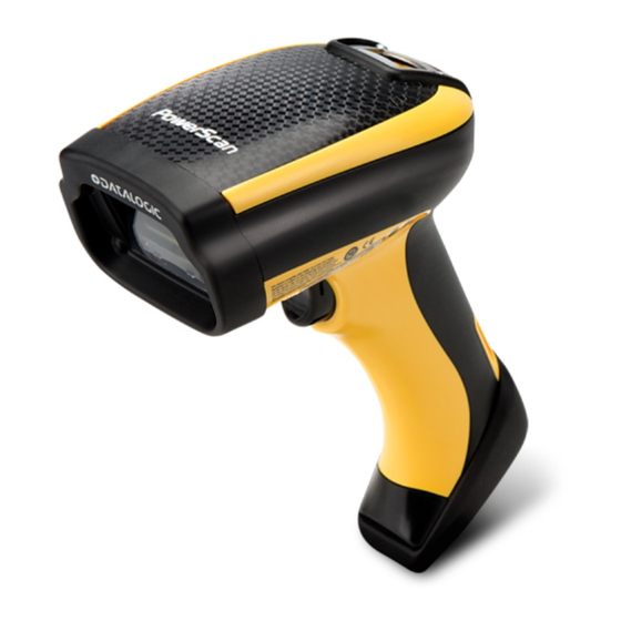
- Page 3 PowerScan™ 9100 Family Linear Imager Bar Code Reader PowerScan PD9130/PBT9100/PM9100 Product Reference Guide...
- Page 4 • All rights reserved. • Without limiting the rights under copyright, no part of this documenta- tion may be reproduced, stored in or introduced into a retrieval system, or transmitted in any form or by any means, or for any purpose, without the express written permission of Datalogic S.p.A. and/or its affiliates.
-
Page 5: Table Of Contents
Set Date and Time ......................................18 Linking the Reader ......................................... 19 Link Datalogic RF Devices to Base ................................19 Linking to a Bluetooth Adapter in Serial Port Profile (Slave) Mode ......................19 Linking to a Bluetooth Adapter in Serial Port Profile (Master) Mode ...................... 19 Linking to a Bluetooth Adapter in HID mode ............................. - Page 6 Contents ACK Character ....................................32 NAK Character ..................................... 32 ACK NAK Timeout Value ................................33 ACK NAK Retry Count .................................. 33 ACK NAK Error Handling ................................34 Indicate Transmission Failure ..............................34 Disable Character ..................................35 Enable Character ..................................35 Keyboard EMULATION Settings ..............................
- Page 7 Contents GTIN FORMATTING ....................................85 EAN 13 (JAN 13) ....................................85 EAN 13 Enable/Disable ................................85 EAN 13 Check Character Transmission ............................. 86 EAN-13 Flag 1 Character ................................86 EAN-13 ISBN Conversion ................................86 ISSN ........................................87 ISSN Enable/Disable ................................... 87 EAN 13 Minimum Reads ................................
- Page 8 Interleaved 2 of 5 Enable/Disable ............................129 DATALOGIC 2 OF 5 ....................................130 Datalogic 2 of 5 Enable/Disable .............................. 130 Datalogic 2 of 5 Check Character Calculation ......................... 130 Datalogic 2 of 5 Check Character Transmission ........................131 Datalogic 2 of 5 Minimum Reads ............................131 Datalogic 2 of 5 Decoding Levels .............................
- Page 9 Contents Code 11 Set Length 2 ................................164 Code 11 Interdigit Ratio ................................165 Code 11 Decoding Levels ................................167 GS1 DATABAR™ OMNIDIRECTIONAL ..............................168 GS1 DataBar™ Omnidirectional Enable/Disable ........................168 GS1 DataBar™ Omnidirectional GS1-128 Emulation ......................168 GS1 DataBar™ Omnidirectional Minimum Reads ........................169 GS1 DATABAR™...
- Page 10 Contents Plessey Length Control ................................207 Plessey Set Length 1 ................................208 Plessey Set Length 2 ................................209 Plessey Minimum Reads ................................210 Plessey Decoding Levels ................................211 Wireless Features ..................................213 WIRELESS BEEPER FEATURES ................................. 217 Good Transmission Beep ................................217 Beep Frequency ..................................
- Page 11 Contents ACTION CONFIGURATION FOR FUNCTION KEYS ..........................261 Configure Actions for F1 ................................261 Configure Actions for F2 ................................262 FUNCTION KEYS CONFIGURATION (16-KEY MODELS ONLY) ......................263 Configure Actions for F3 (16-key models only) ........................263 Configure Actions for F4 (16-key models only) ........................263 Configure Actions for Shift (16-key models only) ........................
- Page 12 Contents TECHNICAL SPECIFICATIONS ................................317 Imager Labeling ........................................320 Standard Cable Pinouts .......................................320 LED and Beeper Indications ....................................321 Base Station Indications (Cordless Models ONLY) ..........................322 SAMPLE BAR CODES..................................... 323 1D Bar Codes .........................................323 GS1 DataBar (RSS) ........................................325 GS1 DataBar-14 ......................................325 STANDARD DEFAULTS..................................327 KEYPAD........................................
-
Page 13: Introduction
Chapter 1 Introduction About this Manual This Product Reference Guide (PRG) is provided for users seeking advanced technical information, including connection, programming, maintenance and specifications. The Quick Reference Guide (QRG) and other publications associated with this product are downloadable free of charge from the web- site listed on the back cover of this manual. -
Page 14: Manual Conventions
Telephone Technical Support If you do not have internet or email access, you may contact Datalogic tech- nical support at (541) 349-8283 or check the back cover of your manual for more contact information. -
Page 15: About The Reader
Typically, units are factory-programmed for the most common terminal and communications settings. If you need to modify any programmable settings, custom configuration can be done by scanning the programming barcodes within this guide or with Datalogic Aladdin™, available from the Datalogic website. See "Datalogic Aladdin™"... -
Page 16: The Bc9Xx0™ Base Station/Charger
Introduction The BC9xx0™ Base Station/Charger The BC9xx0 base station, when paired with one or more PowerScan™ 9100 readers, builds a Cordless Reading System for the collection, decoding and transmission of bar code data. It can be connected to a Host PC via RS-232, USB, or KBD Wedge, and is suited for single-cradle layouts. -
Page 17: Battery Safety
Always charge the battery at 32° – 104°F (0° - 40°C) temperature range. Use only the authorized power supplies, battery pack, chargers, and docks supplied by your Datalogic reseller. The use of any other power supplies can damage the device and CAUTION void your warranty. -
Page 18: Programming The Reader
In addition, Aladdin makes it easy to upgrade the handheld’s firmware, to attain the benefits of new reader features. Reference the Datalogic Aladdin™ Online Help for more details. Aladdin is available for download free of charge on the Datalogic website. PowerScan™ PD9130/PBT9100/PM9100... -
Page 19: Setup
Chapter 2 Setup Unpacking Check carefully to ensure the reader and any accessories ordered are pres- ent and undamaged. If any damage occurred during shipment, contact Dat- alogic Technical Support. Information is shown on page KEEP THE PACKAGING. Should the unit ever require service, it should be returned in its original shipping container. -
Page 20: Connecting The Cable (Corded Versions)
Setup Connecting the Cable (Corded versions) A. Rubber gasket B. Cable Holder C. Cover D. Connector Holder 1. Slip the cable through the Cover. 2. Push the Rubber Gasket onto the Cable Holder. FRONT>> 3. Push the Cable Holder and gasket into the handle. -
Page 21: Configuring The Base Station
Configuring the Base Station Configuring the Base Station To set up your BC9xx0 cradle you must: 1. Physically install the cradle. 2. Make all system connections. 3. Configure the BC9xx0 cradle. Mounting the BC9xx0 Cradle The cradle package contains the following items: BC9xx0 Base Station (with Desktop Mounting 1 Metal Mounting plate Bracket installed) -
Page 22: Permanent Mounting
Setup To change the Bracket: 1. Remove the screw holding the Bracket in place. Retain the screw for re- use. 2. Carefully lift off the Bracket. 3. Install the other bracket by first slipping the end tab into place on the base station, then easing the tabs (shown in Figure 1 on page 9) into... -
Page 23: Mounting For Portable Use
Mounting the BC9xx0 Cradle Mounting for Portable Use If portability of the cradle is required, the metal plate must be used. There are two ways this can be done: (1) by first mounting the metal plate on a flat surface so the cradle can be slid off and on, or (2) mounting the metal plate onto the back of the base station and then screwing both to the desired sur- face. -
Page 24: System Connections
Setup Attaching the Metal Plate to Base Alternatively, the mount can be attached first to the base, then both can be mounted to a wall as described above. Figure 5. Attaching Mounting Plate to Base Base with Mount attached System Connections Connections should always be made with power off! CAUTION The BC9xx0 cradle provides a multi-interface connector and a power supply... -
Page 25: Connecting And Disconnecting The Interface Cable
Mounting the BC9xx0 Cradle Connecting and Disconnecting the Interface Cable The BC9xx0 can be connected to a Host by means of a multi-interface cable, which must be simply plugged into the Host connector, visible on the front panel of the cradle. To disconnect the cable, insert a paper clip or other similar object into the hole corresponding to the Host connector on the body of the cradle. -
Page 26: Bc9Xx0 Configuration
Setup BC9xx0 Configuration The BC9xx0 configuration can be performed in three ways: by using the ™ Datalogic Aladdin software configuration program, by sending configura- tion strings from the Host PC via the RS-232 or USB-COM interface or by ™ reading configuration bar codes with the PowerScan 9100 reader. - Page 27 Set USB-OEM Interface Select USB-OEM Features starting on page USB Keyboard with standard key encoding Select USB Keyboard USB Keyboard with alternate key encoding Select USB Alternate Keyboard a. Download the correct USB Com driver from www.datalogic.com Product Reference Guide...
- Page 28 Setup KEYBOARD FEATURES AT, PS/2 25-286, 30-286, 50, 50Z, 60, 70, 80, 90 & 95 w/Standard Key Encoding Select KBD-AT Keyboard Wedge for IBM AT PS2 with Set KEYBOARD standard key encoding but without WEDGE external keyboard Interface Select KBD-AT-NK Features starting on page 37...
-
Page 29: Customizing Configuration Settings
Customizing Configuration Settings Customizing Configuration Settings Configure Interface Settings If after scanning the interface bar code from the previous table, your instal- lation requires you to select options to further customize your reader, turn to the appropriate section for your interface type in "Configuration Parame- ters"... -
Page 30: Set Date And Time
Setup Restore Factory Configuration The "Restore Custom Default Configuration" command above is normally enough to restart the machine from a known status (set in the factory or by the customer via configuration file). The machine is set as it arrived to you from the factory or according to the custom configuration file you loaded afterward. -
Page 31: Linking The Reader
3. Use the host computer’s Bluetooth manager to “Discover new devices” and select "Datalogic Scanner." If you receive an error message, it may be necessary to disable security on the device. 4. Use an RS-232 terminal program to see incoming data on the port des- ignated by the computer's Bluetooth manager. -
Page 32: Linking To A Bluetooth Adapter In Hid Mode
Link to PC in HID 3. Use the host computer’s Bluetooth manager to “Discover new devices” and select "Datalogic Scanner." If you receive an error message, it may be necessary to disable security on the device. 4. Use a text editor to see incoming data on the port designated by the computer's Bluetooth manager. -
Page 33: Configuration Using Bar Codes
Chapter 3 Configuration Using Bar Codes This and following sections provide programming bar codes to configure your reader by changing the default settings. For details about additional methods of programming, see "Configuration Methods" on page You must first enable your PowerScan to read bar codes in order to Setup, starting use this section. - Page 34 Enter/Exit Programming Mode You must first enable your reader to read bar codes in order to use Setup, starting on this section. If you have not done this, go to page 7 and complete the appropriate procedure. To program features: 1.
-
Page 35: Global Interface Features
Enter/Exit Programming Mode GLOBAL INTERFACE FEATURES The following interface features are configurable by all interface types. Host Commands — Obey/Ignore This option specifies whether the reader will obey or ignore host com- mands. When set to ignore, the reader will ignore all host commands except those necessary for: •... - Page 36 Configuration Using Bar Codes NOTES PowerScan™ PD9130/PBT9100/PM9100...
-
Page 37: Rs-232 Only Interface
RS-232 ONLY INTERFACE on page 26 on page 27 on page 27 ARITY on page 28 ANDSHAKING ONTROL Use the programming bar codes in this section if modifications to the stan- dard RS-232 interface settings are necessary to meet your system’s require- ments. -
Page 38: Baud Rate
Enter/Exit Programming Mode Baud Rate page 286 for information on this feature. Baud Rate = 1200 Baud Rate = 2400 Baud Rate = 4800 Baud Rate = 9600 Baud Rate = 19,200 Baud Rate = 38,400 Baud Rate = 57,600 DEFAULT Baud Rate = 115,200 PowerScan™... -
Page 39: Stop Bits
Enter/Exit Programming Mode Stop Bits Set the number of stop bits to match host device requirements. See page 286 for more information on this feature. DEFAULT 1 Stop Bit 2 Stop Bits Parity This feature specifies parity required for sending and receiving data. Select the parity type according to host device requirements. -
Page 40: Handshaking Control
Enter/Exit Programming Mode Handshaking Control page 286 for more information about this feature. DEFAULT Handshaking Control = RTS Handshaking Control = RTS/CTS Handshaking Control = RTS/XON/XOFF Handshaking Control = RTS On/CTS Handshaking Control = RTS/CTS Scan Control PowerScan™ PD9130/PBT9100/PM9100... -
Page 41: Rs-232/Usb-Com Interfaces
RS-232/USB-COM INTERFACES on page 30 NTERCHARACTER ELAY on page 30 ASCII BEL on page 31 OT ON on page 31 ACK NAK O PTIONS on page 32 ACK C HARACTER on page 32 NAK C HARACTER on page 33 ACK NAK T IMEOUT ALUE on page 33... -
Page 42: Intercharacter Delay
Enter/Exit Programming Mode Intercharacter Delay This parameter specifies the intercharacter delay between the end of one character and the beginning of the next. The delay can be set within a range of zero (0) to 990 milliseconds in 10ms increments. A setting of zero speci- fies no delay. -
Page 43: Beep On Not On File
Enter/Exit Programming Mode Beep On Not on File This option enables/disables the action of the reader to sound a three beep sequence upon receiving a Not-On-File (NOF) host command. Beep On Not On File = Disable DEFAULT Beep On Not On File = Enable ACK NAK Options This enables/disables the ability of the reader to support the RS-232 ACK/ NAK protocol. -
Page 44: Ack Character
Enter/Exit Programming Mode ACK Character This setting specifies an ASCII character or hex value to be used as the ACK character. ASCII characters or any hex value from 0 to 0xFF can be selected. page 288 for more information. To configure this feature, scan the ENTER/EXIT PROGRAMMING MODE bar code above, then the bar code at left followed by the digits from the Alphanu- Appendix D, Keypad... -
Page 45: Ack Nak Timeout Value
Enter/Exit Programming Mode ACK NAK Timeout Value This option specifies the amount of time the reader waits for an ACK char- acter from the host following label transmission. The selectable timeout range is 200 milliseconds to 15,000ms (15 seconds) in 200ms increments. A selection of 0 disables the timeout. -
Page 46: Ack Nak Error Handling
Enter/Exit Programming Mode ACK NAK Error Handling This feature specifies the method the reader uses to handle receive errors detected while waiting for an ACK character from the host. DEFAULT ACK NAK Error Handling = Ignore Errors Detected ACK NAK Error Handling = Process Error as Valid ACK Char- acter ACK NAK Error Handling = Process Error as Valid NAK Character... -
Page 47: Disable Character
Enter/Exit Programming Mode Disable Character Specifies the value of the RS-232 host command used to disable the reader. ASCII characters or any hex value from 0 to 0xFF can be selected. page 292 for more information on setting this feature. To configure this feature, scan the ENTER/EXIT PROGRAMMING MODE bar code above, then the bar code at left followed by the digits from the Alphanu-... - Page 48 NOTES PowerScan™ PD9130/PBT9100/PM9100...
-
Page 49: Keyboard Emulation Settings
KEYBOARD EMULATION SETTINGS on page 38 OUNTRY on page 41 ONTROL HARACTERS on page 42 EDGE UIET NTERVAL on page 42 NTERCODE ELAY on page 43 TATE on page 43 UMLOCK on page 44 USB K EYBOARD PEED on page 45 USB K EYBOARD UMERIC... -
Page 50: Country Mode
Enter/Exit Programming Mode Country Mode This feature specifies the country/language supported by the keyboard. Several languages are supported: DEFAULT Country Mode = U.S. Country Mode = Belgium Country Mode = Britain Country Mode = Denmark Country Mode = France Country Mode = Germany Country Mode = Italy PowerScan™... - Page 51 Enter/Exit Programming Mode Country Mode (continued) Country Mode = Norway Country Mode = Portugal Country Mode = Spain Country Mode = Sweden Country Mode = Switzerland Country Mode = Japanese 106-key Country Mode = Hungary Product Reference Guide...
- Page 52 Enter/Exit Programming Mode Country Mode (continued) Country Mode = Czech Republic Country Mode = Slovakia Country Mode = Romania Country Mode = Croatia Country Mode = Poland Country Mode = French Canadian Country Mode = Lithuanian PowerScan™ PD9130/PBT9100/PM9100...
-
Page 53: Send Control Characters
Enter/Exit Programming Mode Send Control Characters This feature specifies how the reader transmits ASCII control characters to the host. Reference Appendix E, Scancode Tables for more information about control characters. Options are as follows: Characters from 00 to 0x1F are sent as control charac- Control Character 00 : ter Ctrl+Keys, special keys are located from 0x80 to 0xA1. -
Page 54: Wedge Quiet Interval
Enter/Exit Programming Mode Wedge Quiet Interval Specifies amount of time to look for keyboard activity before scanner breaks keyboard connection in order to transmit data to host. The selectable range for this setting is 00 to 990 milliseconds (00-0x63 by 01) in increments of ten milliseconds. -
Page 55: Caps Lock State
Enter/Exit Programming Mode Caps Lock State This option specifies the format in which the reader sends character data. This does not apply when an alternate key encoding keyboard is selected. DEFAULT Caps Lock State = Caps Lock OFF Caps Lock State = Caps Lock ON Caps Lock State = AUTO Caps Lock Enable Numlock This option specifies the setting of the NUMLOCK key in the Keyboard... -
Page 56: Usb Keyboard Speed
Enter/Exit Programming Mode USB Keyboard Speed This option specifies the USB poll rate for a USB keyboard. This feature applies ONLY to the USB Keyboard interface. DEFAULT USB Keyboard Speed = 1ms USB Keyboard Speed = 2ms USB Keyboard Speed = 3ms USB Keyboard Speed = 4ms USB Keyboard Speed = 5ms USB Keyboard Speed = 6ms... -
Page 57: Usb Keyboard Numeric Keypad
Enter/Exit Programming Mode USB Keyboard Speed (continued) USB Keyboard Speed = 7ms USB Keyboard Speed = 8ms USB Keyboard Speed = 9ms USB Keyboard Speed = 10ms USB Keyboard Numeric Keypad This option Controls whether numeric characters will be sent using standard keys or the numeric keypad. - Page 58 NOTES PowerScan™ PD9130/PBT9100/PM9100...
-
Page 59: Usb-Oem Interface
USB-OEM INTERFACE on page 48 USB-OEM D EVICE SAGE on page 48 NTERFACE PTIONS Feature settings for USB interfaces differ depending upon which host type the reader will be connected with. Use the feature settings in this chapter to specifically configure for the USB-OEM interface. Other USB interfaces are included in the appropriate chapter for their host type. -
Page 60: Usb-Oem Device Usage
Enter/Exit Programming Mode USB-OEM Device Usage The USB-OEM protocol allows for the reader to be identified as one of two different types of bar code scanners. Depending on what other scanners you may already have connected to a USB-OEM POS, you may need to change this setting to enable all devices to communicate. -
Page 61: Data Format
DATA FORMAT on page 50 LOBAL REFIX UFFIX EADER ERMINATOR on page 51 AIM ID LOBAL on page 53 AIM ID I GS1-128 NDIVIDUALLY FOR on page 54 ID: P ABEL OADED on page 55 ID C ABEL ONTROL on page 56 ID S ABEL YMBOLOGY... -
Page 62: Global Prefix/Suffix (Header/Terminator)
Enter/Exit Programming Mode Global Prefix/Suffix (Header/Terminator) This option sets up to 20 characters each from the set of ASCII characters or any hex value from 00 to FF. The characters may be added as a prefix (in a position before the bar code data, also called a header) and/or as a suffix (in a position following the bar code data, also called a terminator). -
Page 63: Global Aim Id
Enter/Exit Programming Mode Global AIM ID This feature enables/disables addition of AIM IDs for all sym- bology types. AIM label identifiers (as opposed to custom characters you select yourself as with label identifiers) can be included with scanned bar code data. See the following table for a listing of AIM IDs. - Page 64 Enter/Exit Programming Mode AIM IDs (continued) DATABAR EXPANDED DATABAR EXPANDED COMPOSITE DATABAR LIMITED DATABAR LIMITED COMPOSITE EAN128 EAN128 COMPOSITE EAN13 EAN13 P2 EAN13 P5 EAN13 COMPOSITE EAN8 EAN8 P2 EAN8 P5 EAN8 COMPOSITE FOLLET 2OF5 I2OF5 IATA INDUSTRIAL 2OF5 (Only standard optic models) INDUSTRIAL 2OF5 ISBN ISBT128 CONCAT...
-
Page 65: Set Aim Id Individually For Gs1-128
Enter/Exit Programming Mode AIM IDs (continued) UPCA P2 UPCA P5 UPCA COMPOSITE UPCE UPCE P2 UPCE P5 UPCE COMPOSITE Set AIM ID Individually for GS1-128 This feature configures a Label ID individually for the GS1-128 symbology and the programming for this works the same way as Label ID. See Label ID: Set Individually Per Symbology, starting on page 304 for detailed instruc-... -
Page 66: Label Id
Enter/Exit Programming Mode LABEL ID A Label ID is a customizable code of up to three ASCII characters (convert to Hex using the ASCII Chart on the inside back cover of this manual), used to identify a bar code symbology type. It can be appended previous to or fol- lowing the transmitted bar code data depending upon how this option is enabled. -
Page 67: Individually Set Label Id
Enter/Exit Programming Mode INDIVIDUALLY SET LABEL ID This feature configures a Label ID individually for a single symbology. To set, first define whether you want it as a prefix or suffix by scanning a label below. Then turn to Label ID Symbology Selection, starting on page 56 select the symbology you want to set, followed by up to 3 characters from the ASCII Chart at the back of this manual. -
Page 68: Label Id Symbology Selection
Enter/Exit Programming Mode Label ID Symbology Selection This option selects the symbology for which a Label ID is to be configured. "Label ID" on page 54 or page 304 in “References” for more detailed instructions. If less than the expected string of 3 characters are selected, scan the ENTER/EXIT bar code twice to accept the selection and exit Program- ming Mode. - Page 69 Enter/Exit Programming Mode Label ID Symbology Selection (continued) Set EAN 13 Composite Label ID Character(s) Set Code 128 Label ID Character(s) Set EAN 13 / P2 Label ID Character(s) Set Code 39 Label ID Character(s) Set EAN 13 / P5 Label ID Character(s) Set Code 39 CIP Label ID Character(s) (Only standard optic models) Set GS1 DataBar Expanded Composite...
- Page 70 Enter/Exit Programming Mode Label ID Symbology Selection (continued) Set GS1-128 Composite Label ID Character(s) Set GS1 DataBar Limited Label ID Character(s) Set Follett 2 of 5 Label ID Character(s) (Only standard optic models) Set GS1 DataBar Limited Composite Label ID Character(s) Set GS1 DataBar 14 Label ID Character(s) Set GTIN 2 Label ID Character(s) Set GS1 DataBar 14 Composite Label ID Character(s)
- Page 71 Enter/Exit Programming Mode Label ID Symbology Selection (continued) Set GS1 DataBar Expanded Label ID Character(s) Set GTIN 8 Label ID Character(s) Set IATA Industrial 2 of 5 Label ID Character(s) (Only standard optic models) Set MSI Label ID Character(s) Set Interleaved 2 of 5 Label ID Character(s) Set Plessey Label ID Character(s) (Only standard optic models) Set Industrial 2 of 5 Label ID Character(s)
- Page 72 Enter/Exit Programming Mode Label ID Symbology Selection (continued) Set ISBN Label ID Character(s) Set UPC-A / P2 Label ID Character(s) Set ISSN Label ID Character(s) Set Standard 2 of 5 Label ID Character(s) Set UPC-A Label ID Character(s) Set UPC-A P5 Label ID Character(s) Set UPC-E P5 Label ID Character(s) Set UPC-E Label ID Character(s) Set Codablock F Label ID Character(s)
-
Page 73: Advanced Formatting: User Label Edit
Enter/Exit Programming Mode ADVANCED FORMATTING: USER LABEL EDIT Advanced formatting is available to create user label edit scripts. See the Datalogic Aladdin configuration application or contact Technical Support. Case Conversion This feature allows conversion of the case of all alphabetic characters to upper or lower case. -
Page 74: Character Conversion
Enter/Exit Programming Mode Character Conversion Character conversion is an eight byte configuration item. The eight bytes are 4 character pairs represented in hexadecimal ASCII values. The first charac- ter in the pair is the character that will be converted. The second character in the pair is the character to convert to. -
Page 75: Reading Parameters
READING PARAMETERS on page 64 OUBLE IMEOUT on page 66 OWER LERT on page 66 HEN TO NDICATE on page 67 on page 67 REQUENCY on page 68 ENGTH on page 69 OLUME on page 70 LED D URATION on page 71 on page 72 CANNING CTIVE... -
Page 76: Double Read Timeout
Enter/Exit Programming Mode Double Read Timeout Double Read Timeout prevents a double read of the same label by setting the minimum time allowed between reads of labels of the same symbology and data. If the unit reads a label and sees the same label again within the specified timeout, the second read is ignored. - Page 77 Enter/Exit Programming Mode Double Read Timeout (continued) Double Read Timeout = 0.8 Second Double Read Timeout = 0.9 Second Double Read Timeout = 1 Second Product Reference Guide...
-
Page 78: Led And Beeper Indicators
Enter/Exit Programming Mode LED AND BEEPER INDICATORS Power On Alert Disables or enables the indication (from the Beeper) that the reader is receiving power. Power On Alert = Disable (No Audible Indication) DEFAULT Power On Alert = Power-up Beep Good Read: When to Indicate This feature specifies when the reader will provide indication (beep and/or flash its green LED) upon successfully reading a bar code. -
Page 79: Good Read Beep Type
Enter/Exit Programming Mode Good Read Beep Type Specifies whether the good read beep has a mono or bitonal beep sound. DEFAULT Good Read Beep Type = Mono Good Read Beep Type = Bitonal Good Read Beep Frequency Adjusts the good read beep to sound at a selectable low, medium or high frequency, selectable from the list below. -
Page 80: Good Read Beep Length
Enter/Exit Programming Mode Good Read Beep Length Good Read Beep Length = 60 msec DEFAULT Good Read Beep Length = 80 msec Good Read Beep Length = 100 msec Good Read Beep Length = 120 msec Good Read Beep Length = 140 msec Good Read Beep Length = 160 msec Good Read Beep Length = 180 msec Good Read Beep Length = 200 msec... -
Page 81: Good Read Beep Volume
Enter/Exit Programming Mode Good Read Beep Volume Selects the beeper volume (loudness) upon a good read beep. There are three selectable volume levels. Good Read Beep Volume = Beeper Off Good Read Beep Volume = Low Good Read Beep Volume = Medium DEFAULT Good Read Beep Volume = High Product Reference Guide... -
Page 82: Good Read Led Duration
Enter/Exit Programming Mode Good Read LED Duration This feature specifies the amount of time that the Good Read LED remains on following a good read. The good read LED on time can be set within a range of 100 milliseconds to 25,500 milliseconds (0.1 to 25.5 seconds) in 100ms increments. -
Page 83: Scanning Features
Enter/Exit Programming Mode SCANNING FEATURES Scan Mode Selects the reader’s scan operating mode. See page 308 in “References” for descriptions. DEFAULT Scan Mode = Trigger Single Scan Mode = Trigger Hold Multiple Scan Mode = Trigger Pulse Multiple Scan Mode = Flashing Scan Mode = Always On Product Reference Guide... -
Page 84: Scanning Active Time
Enter/Exit Programming Mode Scanning Active Time This setting specifies the amount of time that the reader stays in scan ON state once the state is entered. The range for this setting is from 1 to 255 seconds in 1-second increments. See page 308 in “References”... -
Page 85: Flash Off Time
Enter/Exit Programming Mode Flash Off Time This feature specifies the OFF time for the indicator LED while in Flash Mode. The selectable range is 100 to 9,900 milliseconds (0.1 to 9.9 sec- onds), in 100 millisecond increments. See page 308 in “References”... -
Page 86: Green Spot Duration
Enter/Exit Programming Mode Green Spot Duration Specifies the duration of the good read pointer beam after a good read. Green Spot Duration = Disable (Green Spot is Off) DEFAULT Green Spot Duration = Short (300 msec) Green Spot Duration = Medium (500 msec) Green Spot Duration = Long (800 msec) PowerScan™... -
Page 87: Symbologies
SYMBOLOGIES The scanner supports the following symbologies (bar code types). Symbol- ogy-dependent options are included in each chapter. on page 78 EAN/UPC on page 79 UPC-A on page 82 UPC-E on page 85 GTIN F ORMATTING on page 85 EAN 13 (J on page 87 ISSN on page 88... - Page 88 on page 170 GS1 D ™ E XPANDED on page 175 GS1 D ™ L IMITED on page 177 on page 184 ODABLOCK F on page 188 on page 190 on page 192 OMMON ONFIGURATION ITEMS on page 194 BC412 on page 200 on page 206 LESSEY...
-
Page 89: Disable All Symbologies
Enter/Exit Programming Mode DISABLE ALL SYMBOLOGIES Use this feature to disable all symbologies. 1. Scan the ENTER/EXIT PROGRAMMING Mode bar code. 2. Scan the Disable All Symbologies bar code. 3. Complete the programming sequence by scanning the ENTER/EXIT PROGRAMMING bar code. Disable All Symbologies This does not disable the reading of programming labels. -
Page 90: Code Ean/Upc
Enter/Exit Programming Mode CODE EAN/UPC Coupon Control This feature is used to control the reader’s method of processing coupon labels. Options are: • Allow all — allow all coupon bar codes to be decoded • UPC/EAN coupon decoding • Enable only GS1 DataBar — enables only GS1 DataBar coupon decoding To set this feature: 1. -
Page 91: Upc-A
Enter/Exit Programming Mode UPC-A The following options apply to the UPC-A symbology. UPC-A Enable/Disable When disabled, the reader will not read UPC-A bar codes. UPC-A = Disable DEFAULT UPC-A = Enable UPC-A Check Character Transmission Enable this option to transmit the check character along with UPC-A bar code data. -
Page 92: Expand Upc-A To Ean-13
Enter/Exit Programming Mode Expand UPC-A to EAN-13 Expands UPC-A data to the EAN-13 data format. Selecting this feature also changes the symbology ID to match those required for EAN-13. DEFAULT UPC-A to EAN-13 = Don’t Expand UPC-A to EAN-13 = Expand UPC-A Number System Character Transmission This feature enables/disables transmission of the UPC-A number system character. -
Page 93: In-Store Minimum Reads
Enter/Exit Programming Mode In-Store Minimum Reads This feature specifies the minimum number of consecutive times an in- store label must be decoded before it is accepted as good read. In-store labels are defined as UPC-A labels with a number-system character of 2 or 4 as well as EAN 8 and EAN 13 labels with a Flag1 character of 2 or an EAN 13 label starting with the three characters '980'. -
Page 94: Upc-E
Enter/Exit Programming Mode UPC-E The following options apply to the UPC-E symbology. UPC-E Enable/Disable When disabled, the reader will not read UPC-E bar codes. UPC-E = Disable DEFAULT UPC-E = Enable UPC-E Check Character Transmission Enable this option to transmit the check character along with UPC-E bar code data. -
Page 95: Expand Upc-E To Ean-13
Enter/Exit Programming Mode Expand UPC-E to EAN-13 Expands UPC-E data to the EAN-13 data format. Selecting this feature also changes the symbology ID to match those required for EAN-13. DEFAULT UPC-E to EAN-13 = Don’t Expand UPC-E to EAN-13 = Expand Expand UPC-E to UPC-A Expands UPC-E data to the UPC-A data format. -
Page 96: Upc-E Number System Character Transmission
Enter/Exit Programming Mode UPC-E Number System Character Transmission This feature enables/disables transmission of the UPC-E system number character. UPC-E Number System Character = Do not transmit DEFAULT UPC-E Number System Character = Transmit UPC-E Minimum Read This feature specifies the minimum number of consecutive times a UPC-E label must be decoded before it is accepted as good read. -
Page 97: Gtin Formatting
Enter/Exit Programming Mode GTIN FORMATTING This feature enables/disables the ability to convert UPC-E, UPC-A, and EAN 13 labels into the GTIN 14-character format. If add-on information is present on the base label prior to the conversion taking place, the add-on information will be appended to the converted GTIN label. -
Page 98: Ean 13 Check Character Transmission
Enter/Exit Programming Mode EAN 13 Check Character Transmission Enable this option to transmit the check character along with EAN 13 bar code data. EAN 13 Check Character Transmission = Don’t Send DEFAULT EAN 13 Check Character Transmission = Send EAN-13 Flag 1 Character Enables/disables transmission of an EAN/JAN13 Flag1 character. -
Page 99: Issn
Enter/Exit Programming Mode ISSN The following options apply to the ISSN symbology. ISSN Enable/Disable Enables/disables conversion of EAN/JAN13 Bookland labels starting with 977 to ISSN labels. DEFAULT ISSN = Disable ISSN = Enable EAN 13 Minimum Reads This feature specifies the minimum number of consecutive times an EAN 13 label must be decoded before it is accepted as good read. -
Page 100: Ean 8
Enter/Exit Programming Mode EAN 8 The following options apply to the ISSN symbology. EAN 8 Enable/Disable The following options apply to the ISSN symbology. EAN 8 = Disable DEFAULT EAN 8 = Enable EAN 8 Check Character Transmission Enable this option to transmit the check character along with EAN 8 barcode data EAN 8 Check Character Transmission = Don’t Send DEFAULT... -
Page 101: Ean 8 To Ean 13
Enter/Exit Programming Mode EAN 8 to EAN 13 Enable this option to expand EAN 8/JAN 8 labels to EAN 13/Jan 13. DEFAULT Expand EAN 8 to EAN 13 = Disable Expand EAN 8 to EAN 13 = Enable EAN 8 Minimum Reads This feature specifies the minimum number of consecutive times an EAN 8 (Jan 8) label must be decoded before it is accepted as good read. -
Page 102: Upc/Ean Global Settings
Enter/Exit Programming Mode UPC/EAN GLOBAL SETTINGS This section provides configuration settings for UPC-A, UPC-E, EAN 13 sym- bologies, and affects all of these unless otherwise marked for each feature description. UPC/EAN Decoding Levels Decoding Levels are used to configure a bar code symbology decoder to be very aggressive to very conservative depending on a particular customer’s needs UPC/EAN Decoding Level = 1... -
Page 103: Upc/Ean Price Weight Check
Enter/Exit Programming Mode UPC/EAN Price Weight Check This feature enables/disables calculation and verification of price/weight check digits. Options are: • Disabled • Enable 4-digit price-weight check-digit calculation • Enable 5-digit price-weight check-digit calculation • Enable European 4-digit price-weight check-digit calculation •... -
Page 104: Upc-A Minimum Reads
Enter/Exit Programming Mode UPC-A Minimum Reads This feature specifies the minimum number of consecutive times a UPC-A label must be decoded before it is accepted as good read. DEFAULT UPC-A Minimum Reads = 1 UPC-A Minimum Reads = 2 UPC-A Minimum Reads = 3 UPC-A Minimum Reads = 4 UPC/EAN Quiet Zones This feature specifies the number of quiet zones for UPC/EAN labels. -
Page 105: Add-Ons
Enter/Exit Programming Mode ADD-ONS Contact Customer Support for advanced programming of optional and con- ditional add-ons. Contact Customer Support for advanced programming of optional and condi- tional add-ons. Optional Add-ons The reader can be enabled to optionally read the following add-ons (sup- plementals): •... -
Page 106: Optional Add-On Timer
Enter/Exit Programming Mode Optional Add-On Timer This option sets the time the reader will look for an add-on when an add-on fragment has been seen and optional add-ons are enabled. Optional Add-on Timer = 10ms Optional Add-on Timer = 20ms Optional Add-on Timer = 30ms Optional Add-on Timer = 50ms DEFAULT... -
Page 107: P2 Add-Ons Minimum Reads
Enter/Exit Programming Mode P2 Add-Ons Minimum Reads This feature specifies the minimum number of times a P2 add-on must be read before it is marked as valid and then combined with a base label. P2 Add-Ons Minimum Reads = 1 DEFAULT P2 Add-Ons Minimum Reads = 2 P2 Add-Ons Minimum Reads = 3... -
Page 108: P5 Add-Ons Minimum Reads
Enter/Exit Programming Mode P5 Add-Ons Minimum Reads This feature specifies the minimum number of times a P5 add-on must be read before it is marked as valid and then combined with a base label. DEFAULT P5 Add-Ons Minimum Reads = 1 P5 Add-Ons Minimum Reads = 2 P5 Add-Ons Minimum Reads = 3 P5 Add-Ons Minimum Reads = 4... -
Page 109: Code 39
Enter/Exit Programming Mode CODE 39 The following options apply to the Code 39 symbology. Code 39 Enable/Disable Code 39 = Disable DEFAULT Code 39 = Enable Code 39 Check Character Calculation Enable this option to enables/disables calculation and verification of an optional Code 39 check character. -
Page 110: Code 39 Check Character Transmission
Enter/Exit Programming Mode Code 39 Check Character Calculation (continued) Code 39 Check Character Calculation = Enable Italian Post Check (no AR) Code 39 Check Character Calculation = Enable Daimler Chrysler Check (no AR) Code 39 Check Character Transmission Enable this option to transmit the check character along with Code 39 bar code data. -
Page 111: Code 39 Start/Stop Character Transmission
Enter/Exit Programming Mode Code 39 Start/Stop Character Transmission Enable this option to enable/disable transmission of Code 39 start and stop characters DEFAULT Code 39 Start/Stop Character Transmission = Don’t Transmit Code 39 Start/Stop Character Transmission = Transmit Code 39 Full ASCII Enables/disables the translation of Code 39 characters to Code 39 full- ASCII characters. -
Page 112: Code 39 Quiet Zones
Enter/Exit Programming Mode Code 39 Quiet Zones This feature specifies the number of quiet zones for Code 39 labels. Quiet zones are blank areas at the ends of a bar code, typically 10 times the width of the narrowest bar or space in the label. Code 39 Quiet Zones = Quiet Zone on one side Code 39 Quiet Zones = Quiet Zones on two sides DEFAULT... -
Page 113: Code 39 Minimum Reads
Enter/Exit Programming Mode Code 39 Minimum Reads This feature specifies the minimum number of consecutive times a Code 39 label must be decoded before it is accepted as good read. Code 39 Minimum Reads = 1 DEFAULT Code 39 Minimum Reads = 2 Code 39 Minimum Reads = 3 Code 39 Minimum Reads = 4 Product Reference Guide... -
Page 114: Code 39 Decoding Levels
Enter/Exit Programming Mode Code 39 Decoding Levels Decoding Levels are used to configure a bar code symbology decoder to be very aggressive to very conservative depending on a particular customer’s needs. Code 39 Decoding Level = Disable Code 39 Decoding Level = 1 Code 39 Decoding Level = 2 DEFAULT Code 39 Decoding Level = 3... -
Page 115: Code 39 Length Control
Enter/Exit Programming Mode Code 39 Length Control This feature specifies either variable length decoding or fixed length decod- ing for the Code 39 symbology. For variable length decoding, a minimum and maximum Variable Length. length may be set. For fixed length decoding, two different lengths may be set. Fixed Length. -
Page 116: Code 39 Set Length 1
Enter/Exit Programming Mode Code 39 Set Length 1 This feature specifies one of the bar code lengths for Code 39 Length Con- trol. Length 1 is the minimum label length if in Variable Length Mode, or the first fixed length if in Fixed Length Mode. -
Page 117: Code 39 Set Length 2
Enter/Exit Programming Mode Code 39 Set Length 2 This feature specifies one of the bar code lengths for Code 39 Length Con- trol. Length 2 is the maximum label length if in Variable Length Mode, or the second fixed length if in Fixed Length Mode. -
Page 118: Code 39 Interdigit Ratio
Enter/Exit Programming Mode Code 39 Interdigit Ratio This feature specifies the ratio between an intercharacter space and module for Code 39 labels. Code 39 Interdigit Ratio = Disable Code 39 Interdigit Ratio = 1 Code 39 Interdigit Ratio = 2 Code 39 Interdigit Ratio = 3 DEFAULT Code 39 Interdigit Ratio = 4... -
Page 119: Code 32 (Ital Pharmaceutical Code)
Enter/Exit Programming Mode CODE 32 (ITAL PHARMACEUTICAL CODE) The following options apply to the Code 32 (Italian Pharmaceutical Code) symbology. Code 32 Enable/Disable When disabled, the reader will not read Code 32 bar codes. DEFAULT Code 32 = Disable Code 32 = Enable Code 32 Feature Setting Exceptions The following features are set for Code 32 by using these Code 39 settings: "Code 39 Quiet Zones"... -
Page 120: Code 32 Start/Stop Character Transmission
Enter/Exit Programming Mode Code 32 Start/Stop Character Transmission This option enables/disables transmission of Code 32 start and stop char- acters DEFAULT Code 32 Start/Stop Character Transmission = Don’t Transmit Code 32 Start/Stop Character Transmission = Transmit CODE 39 CIP (FRENCH PHARMACEUTICAL) The following options apply to the Code 39 CIP symbology. -
Page 121: Code 128
Enter/Exit Programming Mode CODE 128 The following options apply to the Code 128 symbology. Code 128 Enable/Disable When disabled, the reader will not read Code 128 bar codes. Code 128 = Disable DEFAULT Code 128 = Enable Expand Code 128 to Code 39 This feature enables/disables expansion of Code 128 labels to Code 39 labels. -
Page 122: Code 128 Check Character Transmission
Enter/Exit Programming Mode Code 128 Check Character Transmission Enable this option to transmit the check character along with Code 128 bar code data. DEFAULT Code 128 Check Character Transmission = Don’t Send Code 128 Check Character Transmission = Send Code 128 Function Character Transmission Enables/disables transmission of Code128 function characters 1, 2, 3, and DEFAULT Code 128 Function Character Transmission = Don’t Send... -
Page 123: Code 128 Sub-Code Exchange Transmission
Enter/Exit Programming Mode Code 128 Sub-Code Exchange Transmission Enables/disables the transmission of “Sub-Code Exchange” characters (NOT transmitted by standard decoding). DEFAULT Code 128 Sub-Code Exchange Transmission = Disable Code 128 Sub-Code Exchange Transmission = Enable Code 128 Quiet Zones This feature specifies the number of quiet zones for Code 128 labels. Quiet zones are blank areas at the ends of a bar code and are typically 10 times the width of the narrowest bar or space in the label. -
Page 124: Code 128 Minimum Reads
Enter/Exit Programming Mode Code 128 Minimum Reads This feature specifies the minimum number of consecutive times a Code 128 label must be decoded before it is accepted as good read DEFAULT Code 128 Minimum Reads = 1 Code 128 Minimum Reads = 2 Code 128 Minimum Reads = 3 Code 128 Minimum Reads = 4 PowerScan™... -
Page 125: Code 128 Decoding Levels
Enter/Exit Programming Mode Code 128 Decoding Levels Decoding Levels are used to configure a bar code symbology decoder to be very aggressive to very conservative depending on a particular customer’s needs Code 128 Decoding Level = Disable Code 128 Decoding Level = 1 Code 128 Decoding Level = 2 DEFAULT Code 128 Decoding Level = 3... -
Page 126: Code 128 Length Control
Enter/Exit Programming Mode Code 128 Length Control This feature specifies either variable length decoding or fixed length decod- ing for the Code 128 symbology. For variable length decoding, a minimum and maximum Variable Lenght. length may be set. Fixed Lenght. For fixed length decoding, two different lengths may be set. -
Page 127: Code 128 Set Length 1
Enter/Exit Programming Mode Code 128 Set Length 1 Specifies one of the bar code lengths for Code 128 Length Control. Length 1 is the minimum label length if in Variable Length Mode, or the first fixed length if in Fixed Length Mode. -
Page 128: Code 128 Set Length 2
Enter/Exit Programming Mode Code 128 Set Length 2 This feature specifies one of the bar code lengths for Code 128 Length Con- trol. Length 2 is the maximum label length if in Variable Length Mode, or the second fixed length if in Fixed Length Mode. -
Page 129: Gs1-128
Enter/Exit Programming Mode GS1-128 The following options apply to the GS1-128 symbology. (Also known as USS-128, GS1-128, GTIN-128, UCC-128, EAN-128.) GS1-128 Enable This option enables/disables the ability of the reader to translate GS1-128 labels to the GS1-128 data format. Options are: •... -
Page 130: Code Isbt 128
Enter/Exit Programming Mode CODE ISBT 128 The following options apply to the ISBT 128 symbology. ISBT 128 Concatenation Use this option to enable/disable ISBT128 concatenation of 2 labels. DEFAULT ISBT 128 Concatenation = Disable ISBT 128 Concatenation = Enable ISBT 128 Force Concatenation When enabled, this feature forces concatenation for ISBT. -
Page 131: Isbt 128 Concatenation Mode
Enter/Exit Programming Mode ISBT 128 Concatenation Mode Specifies the concatenation mode between Static and Dynamic. ISBT 128 This option is only valid when ISBT 128 Concatenation is enabled (see " Concatenation" on page 118 DEFAULT ISBT 128 Concatenation Mode = Static ISBT 128 Concatenation Mode = Dynamic Product Reference Guide... -
Page 132: Isbt 128 Dynamic Concatenation Timeout
Enter/Exit Programming Mode ISBT 128 Dynamic Concatenation Timeout Specifies the timeout used by the ISBT 128 Dynamic Concatenation Mode. ISBT 128 Dynamic Concatenation Timeout = 50 msec ISBT 128 Dynamic Concatenation Timeout = 100 msec DEFAULT ISBT 128 Dynamic Concatenation Timeout = 200 msec ISBT 128 Dynamic Concatenation Timeout = 500 msec ISBT 128 Dynamic Concatenation Timeout = 750 msec ISBT 128 Dynamic Concatenation Timeout = 1 second... -
Page 133: Isbt 128 Advanced Concatenation Options
Enter/Exit Programming Mode ISBT 128 Advanced Concatenation Options To set up pairs of label types for concatenation, use the Datalogic Aladdin configura- page 2 tion application or contact Datalogic Technical Support, as described on INTERLEAVED 2 OF 5 (I 2 OF 5) The following options apply to the I 2 of 5 symbology. -
Page 134: I 2 Of 5 Check Character Calculation
Enter/Exit Programming Mode I 2 of 5 Check Character Calculation This option enables/disables calculation and verification of an optional I 2 of 5 check character. Combinations of these settings are possible via the Alad- din configuration utility, or contact Technical Support. DEFAULT I 2 of 5 Check Character Calculation = Disable I 2 of 5 Check Character Calculation = Check Standard... -
Page 135: I 2 Of 5 Check Character Transmission
Enter/Exit Programming Mode I 2 of 5 Check Character Transmission Enable this option to transmit the check character along with I 2 of 5 bar code data. This feature is valid only when I 2 of 5 Check Character Calculation is enabled. I 2 of 5 Check Character Transmission = Don’t Send DEFAULT I 2 of 5 Check Character Transmission = Send... -
Page 136: I 2 Of 5 Decoding Levels
Enter/Exit Programming Mode I 2 of 5 Decoding Levels This configuration item applies to Interleaved 2 of 5, Datalogic 2 of 5 and Stan- dard 2 of 5. Decoding Levels are used to configure a bar code symbology decoder to be very aggressive to very conservative depending on a particular customer’s... -
Page 137: I 2 Of 5 Length Control
Enter/Exit Programming Mode I 2 of 5 Length Control This feature specifies either variable length decoding or fixed length decod- ing for the I 2 of 5 symbology. For variable length decoding, a minimum and maximum Variable Length: length may be set. For fixed length decoding, two different lengths may be set. -
Page 138: I 2 Of 5 Set Length 1
Enter/Exit Programming Mode I 2 of 5 Set Length 1 This feature specifies one of the bar code lengths for I 2 of 5 Length Control. Length 1 is the minimum label length if in Variable Length Mode, or the first fixed length if in Fixed Length Mode. -
Page 139: I 2 Of 5 Set Length 2
Enter/Exit Programming Mode I 2 of 5 Set Length 2 This feature specifies one of the bar code lengths for I 2 of 5 Length Con- trol. Length 2 is the maximum label length if in Variable Length Mode, or the second fixed length if in Fixed Length Mode. -
Page 140: I 2 Of 5 Zero Pattern
Enter/Exit Programming Mode I 2 of 5 Zero Pattern Enables/disables ZERO-Digit decoding. This character does not represent any cipher. It allows encoding of an odd number of ciphers with Interleaved 2 of 5. It must be enabled to decode Code 2 of 5 CIP/HR. DEFAULT I 2 of 5 Zero Pattern = Disable I 2 of 5 Zero Pattern = Enable... -
Page 141: Interleaved 2 Of 5 Cip Hr
Enter/Exit Programming Mode INTERLEAVED 2 OF 5 CIP HR The following options apply to the Interleaved 2 of 5 CIP HR symbology. Interleaved 2 of 5 Enable/Disable Enables/Disables ability of reader to decode Interleaved 2 of 5 CIP HR labels. DEFAULT Interleaved 2 of 5 CIP HR = Disable Interleaved 2 of 5 CIP HR = Enable... -
Page 142: Datalogic 2 Of 5
DATALOGIC 2 OF 5 The following options apply to the Datalogic 2 of 5 symbology. Datalogic 2 of 5 Enable/Disable When disabled, the scanner will not read Datalogic 2 of 5 bar codes. DEFAULT Datalogic 2 of 5 = Disable... -
Page 143: Datalogic 2 Of 5 Check Character Transmission
Enter/Exit Programming Mode Datalogic 2 of 5 Check Character Transmission This option enables/disables transmission of an optional Datalogic 2 of 5 character. Datalogic 2 of 5 Check Character Transmission = Don’t Send DEFAULT Datalogic 2 of 5 Check Character Transmission = Send... -
Page 144: Datalogic 2 Of 5 Length Control
Fixed Length. For fixed length decoding, two different lengths may be set. DEFAULT Datalogic 2 of 5 Length Control = Variable Length Datalogic 2 of 5 Length Control = Fixed Length Datalogic 2 of 5 Set Length 1 This feature specifies one of the bar code lengths for... -
Page 145: Datalogic 2 Of 5 Set Length 2
Appendix D, Keypad representing your desired character(s). End by scanning the ENTER/EXIT bar Select Datalogic 2 of 5 Length 2 Setting code again. Make a mistake? Scan the CANCEL bar code to abort and not save the entry string. You can then start again at the beginning. -
Page 146: Datalogic 2 Of 5 Interdigit Maximum Ratio
This feature specifies the maximum ratio between intercharacter space and module for Datalogic 2 of 5. Datalogic 2 of 5 Interdigit Ratio = Disable Datalogic 2 of 5 Interdigit Ratio = 1 Datalogic 2 of 5 Interdigit Ratio = 2... -
Page 147: Follett 2 Of 5 (Only Standard Optic Models)
Enter/Exit Programming Mode Datalogic 2 of 5 Interdigit Ratio = 6 Datalogic 2 of 5 Interdigit Ratio = 7 Datalogic 2 of 5 Interdigit Ratio = 8 Datalogic 2 of 5 Interdigit Ratio = 9 Datalogic 2 of 5 Interdigit Ratio = 10... -
Page 148: Standard 2 Of 5
Enter/Exit Programming Mode STANDARD 2 OF 5 The following options apply to the Standard 2 of 5 symbology. Standard 2 of 5 Enable/Disable When disabled, the reader will not read Standard 2 of 5 bar codes. DEFAULT Standard 2 of 5 = Disable Standard 2 of 5 = Enable Standard 2 of 5 Check Character Calculation This option enables/disables calculation and verification of an optional... -
Page 149: Standard 2 Of 5 Check Character Transmission
Enter/Exit Programming Mode Standard 2 of 5 Check Character Transmission This feature enables/disables transmission of an optional Standard 2 of 5 check character. Standard 2 of 5 Check Character Transmission = Don’t Send DEFAULT Standard 2 of 5 Check Character Transmission = Send Standard 2 of 5 Minimum Reads This feature specifies the minimum number of consecutive times a Standard 2 of 5 label must be decoded before it is accepted as good read. -
Page 150: Standard 2 Of 5 Decoding Levels
Enter/Exit Programming Mode Standard 2 of 5 Decoding Levels "I 2 of 5 Decoding Level" The Standard 2 of 5 Decoding Level feature is set using on page 135. Standard 2 of 5 Length Control This feature specifies either variable length decoding or fixed length decod- ing for the Standard 2 of 5 symbology. -
Page 151: Standard 2 Of 5 Set Length 1
Enter/Exit Programming Mode Standard 2 of 5 Set Length 1 This feature specifies one of the bar code lengths for Standard 2 of 5 Length Control. Length 1 is the minimum label length if in Variable Length Mode, or the first fixed length if in Fixed Length Mode. -
Page 152: Standard 2 Of 5 Set Length 2
Enter/Exit Programming Mode Standard 2 of 5 Set Length 2 This feature specifies one of the bar code lengths for Standard 2 of 5 Length Control. Length 2 is the maximum label length if in Variable Length Mode, or the second fixed length if in Fixed Length Mode. -
Page 153: Industrial 2 Of 5 (Only Standard Optic Models)
Enter/Exit Programming Mode INDUSTRIAL 2 OF 5 ( ONLY STANDARD OPTIC MODELS The following options apply to the Industrial 2 of 5 symbology. Industrial 2 of 5 Enable/Disable Enables/Disables ability of reader to decode Industrial 2 of 5 labels. DEFAULT Industrial 2 of 5 = Disable Industrial 2 of 5 = Enable Industrial 2 of 5 Check Character Calculation... -
Page 154: Industrial 2 Of 5 Check Character Transmission
Enter/Exit Programming Mode Industrial 2 of 5 Check Character Transmission Enables/disables transmission of an Industrial 2 of 5 check character. Industrial 2 of 5 Check Character Transmission = Disable DEFAULT Industrial 2 of 5 Check Character Transmission = Enable Industrial 2 of 5 Length Control This feature specifies either variable length decoding or fixed length decod- ing for the Industrial 2 of 5 symbology. -
Page 155: Industrial 2 Of 5 Set Length 1
Enter/Exit Programming Mode Industrial 2 of 5 Set Length 1 This feature specifies one of the bar code lengths for Industrial 2 of 5 Length Control. Length 1 is the minimum label length if in Variable Length Mode, or the first fixed length if in Fixed Length Mode. -
Page 156: Industrial 2 Of 5 Set Length 2
Enter/Exit Programming Mode Industrial 2 of 5 Set Length 2 This feature specifies one of the bar code lengths for Industrial 2 of 5 Length Control. Length 2 is the maximum label length if in Variable Length Mode, or the second fixed length if in Fixed Length Mode. -
Page 157: Industrial 2 Of 5 Minimum Reads
Enter/Exit Programming Mode Industrial 2 of 5 Minimum Reads This feature specifies the minimum number of consecutive times an Indus- trial 2 of 5 label must be decoded before it is accepted as good read. DEFAULT Industrial 2 of 5 Minimum Reads = 1 Industrial 2 of 5 Minimum Reads = 2 Industrial 2 of 5 Minimum Reads = 3 Industrial 2 of 5 Minimum Reads = 4... -
Page 158: Code Iata (Only Standard Optic Models)
Enter/Exit Programming Mode CODE IATA ( ONLY STANDARD OPTIC MODELS The following options apply to the IATA symbology. IATA Enable/Disable Enables/Disables the ability of the reader to decode IATA labels. DEFAULT IATA = Disable IATA = Enable IATA Check Character Transmission Enables/Disables calculation and verification of an optional Industrial 2 of 5 check character. -
Page 159: Codabar
Enter/Exit Programming Mode CODABAR The following options apply to the Codabar symbology. Codabar Enable/Disable When disabled, the reader will not read Codabar bar codes. DEFAULT Codabar = Disable Codabar = Enable Codabar Check Character Calculation Enable this option to enables/disables calculation and verification of an optional Codabar check character. -
Page 160: Codabar Check Character Transmission
Enter/Exit Programming Mode Codabar Check Character Transmission Enable this option to transmit the check character along with Codabar bar code data. Codabar Check Character Transmission = Don’t Send DEFAULT Codabar Check Character Transmission = Send Codabar Start/Stop Character Transmission Enable this option to enable/disable transmission of Codabar start and stop characters Codabar Start/Stop Character Transmission = Don’t Transmit... -
Page 161: Codabar Start/Stop Character Set
Enter/Exit Programming Mode Codabar Start/Stop Character Set This option specifies the format of transmitted Codabar start/stop charac- ters Codabar Check Character Set = ABCD/TN*E Codabar Check Character Set = ABCD/ABCD Codabar Check Character Set = abcd/tn*e DEFAULT Codabar Check Character Set = abcd/abcd Codabar Start/Stop Character Match When enabled, this option requires that start and stop characters match DEFAULT... -
Page 162: Codabar Quiet Zones
Enter/Exit Programming Mode Codabar Quiet Zones Specifies the number of quiet zones for Codabar labels. Quiet zones are blank areas at the ends of a bar code and are typically 10 times the width of the narrowest bar or space in the label. Codabar Quiet Zones = Quiet Zone on one side Codabar Quiet Zones = Quiet Zones on two sides DEFAULT... -
Page 163: Codabar Minimum Reads
Enter/Exit Programming Mode Codabar Minimum Reads This feature specifies the minimum number of consecutive times a Codabar label must be decoded before it is accepted as good read. DEFAULT Codabar Minimum Reads = 1 Codabar Minimum Reads = 2 Codabar Minimum Reads = 3 Codabar Minimum Reads = 4 Product Reference Guide... -
Page 164: Codabar Decoding Levels
Enter/Exit Programming Mode Codabar Decoding Levels Decoding Levels are used to configure a bar code symbology decoder to be very aggressive to very conservative depending on a particular customer’s needs Codabar Decoding Level = Disable Codabar Decoding Level = 1 Codabar Decoding Level = 2 DEFAULT Codabar Decoding Level = 3... -
Page 165: Codabar Length Control
Enter/Exit Programming Mode Codabar Length Control This feature specifies either variable length decoding or fixed length decod- ing for the Codabar symbology. For variable length decoding, a minimum and maximum Variable Length. length may be set. For fixed length decoding, two different lengths may be set. Fixed Length. -
Page 166: Codabar Set Length 1
Enter/Exit Programming Mode Codabar Set Length 1 This feature specifies one of the bar code lengths for Codabar Length Con- trolCodabar Length Control. Length 1 is the minimum label length if in Vari- able Length Mode, or the first fixed length if in Fixed Length Mode. -
Page 167: Codabar Set Length 2
Enter/Exit Programming Mode Codabar Set Length 2 This feature specifies one of the bar code lengths for Codabar Length Con- trolCodabar Length Control. Length 2 is the maximum label length if in Variable Length Mode, or the second fixed length if in Fixed Length Mode. -
Page 168: Codabar Interdigit Ratio
Enter/Exit Programming Mode Codabar Interdigit Ratio This feature specifies the maximum ratio between an intercharacter space and module for Codabar labels. Codabar Interdigit Ratio = Disable Codabar Interdigit Ratio = 1 Codabar Interdigit Ratio = 2 Codabar Interdigit Ratio = 3 DEFAULT Codabar Interdigit Ratio = 4 Codabar Interdigit Ratio = 5... - Page 169 Enter/Exit Programming Mode Codabar Interdigit Ratio (continued) Codabar Interdigit Ratio = 6 Codabar Interdigit Ratio = 7 Codabar Interdigit Ratio = 8 Codabar Interdigit Ratio = 9 Codabar Interdigit Ratio = 10 Product Reference Guide...
-
Page 170: Abc Codabar
Enter/Exit Programming Mode ABC CODABAR The following options apply to the ABC Codabar symbology. ABC Codabar Enable/Disable Enables/Disables ability of scanner to decode ABC Codabar labels. DEFAULT ABC Codabar = Disable ABC Codabar = Enable ABC Codabar Concatenation Mode Specifies the concatenation mode between Static and Dynamic. DEFAULT ABC Codabar Concatenation Mode = Static ABC Codabar Concatenation Mode = Dynamic... -
Page 171: Abc Codabar Dynamic Concatenation Timeout
Enter/Exit Programming Mode ABC Codabar Dynamic Concatenation Timeout This parameter specifies the timeout in 10-millisecond ticks used by the ABC Codabar Dynamic Concatenation Mode. The timeout can be set within a range of 05 to 255 in 10ms increments. A setting of zero specifies no delay. To configure this feature, scan the ENTER/EXIT bar code above, then the bar code at left fol- lowed by digits from the Alphanumeric charac-... -
Page 172: Code 11 (Only Standard Optic Models)
Enter/Exit Programming Mode CODE 11 ( ONLY STANDARD OPTIC MODELS The following options apply to the Code 11 symbology. Code 11 Enable/Disable When disabled, the reader will not read Code 11 bar codes. DEFAULT Code 11 = Disable Code 11 = Enable Code 11 Check Character Calculation This option enables/disables calculation and verification of optional Code 11 check character. -
Page 173: Code 11 Check Character Transmission
Enter/Exit Programming Mode Code 11 Check Character Transmission This feature enables/disables transmission of an optional Code 11 check character. Code 11 Check Character Transmission = Don’t Send DEFAULT Code 11 Check Character Transmission = Send Code 11 Minimum Reads This feature specifies the minimum number of consecutive times a Code 11 label must be decoded before it is accepted as good read. -
Page 174: Code 11 Length Control
Enter/Exit Programming Mode Code 11 Length Control This feature specifies either variable length decoding or fixed length decod- ing for the Code 11 symbology. For variable length decoding, a minimum and maximum Variable Length. length may be set. For fixed length decoding, two different lengths may be set. Fixed Length. -
Page 175: Code 11 Set Length 1
Enter/Exit Programming Mode Code 11 Set Length 1 This feature specifies one of the bar code lengths for Code 11 Length Con- trol. Length 1 is the minimum label length if in Variable Length Mode, or the first fixed length if in Fixed Length Mode. -
Page 176: Code 11 Set Length 2
Enter/Exit Programming Mode Code 11 Set Length 2 This feature specifies one of the bar code lengths for Code 11 Length Con- trol. Length 2 is the maximum label length if in Variable Length Mode, or the second fixed length if in Fixed Length Mode. -
Page 177: Code 11 Interdigit Ratio
Enter/Exit Programming Mode Code 11 Interdigit Ratio This feature specifies the ratio between an intercharacter space and module for Code 11 labels Code 11 Interdigit Ratio = Disable Code 11 Interdigit Ratio = 1 Code 11 Interdigit Ratio = 2 Code 11 Interdigit Ratio = 3 DEFAULT Code 11 Interdigit Ratio = 4... - Page 178 Enter/Exit Programming Mode Code 11 Interdigit Ratio (continued) Code 11 Interdigit Ratio = 6 Code 11 Interdigit Ratio = 7 Code 11 Interdigit Ratio = 8 Code 11 Interdigit Ratio = 9 Code 11 Interdigit Ratio = 10 PowerScan™ PD9130/PBT9100/PM9100...
-
Page 179: Code 11 Decoding Levels
Enter/Exit Programming Mode Code 11 Decoding Levels Decoding Levels are used to configure a bar code symbology decoder to be very aggressive to very conservative depending on a particular customer’s needs Code 11 Decoding Level = Disable Code 11 Decoding Level = 1 Code 11 Decoding Level = 2 DEFAULT Code 11 Decoding Level = 3... -
Page 180: Gs1 Databar™ Omnidirectional
Enter/Exit Programming Mode GS1 DATABAR™ OMNIDIRECTIONAL The following options apply to the GS1 DataBar™ Omnidirectional (formerly RSS-14) symbology. GS1 DataBar™ Omnidirectional Enable/Disable When disabled, the reader will not read GS1 DataBar™ Omnidirectional bar codes. DEFAULT GS1 DataBar™ Omnidirectional = Disable GS1 DataBar™... -
Page 181: Gs1 Databar™ Omnidirectional Minimum Reads
Enter/Exit Programming Mode GS1 DataBar™ Omnidirectional Minimum Reads This feature specifies the minimum number of consecutive times a GS1 DataBar Omnidirectional label must be decoded before it is accepted as good read. DEFAULT GS1 DataBar Omnidirectional Minimum Reads = 1 GS1 DataBar Omnidirectional Minimum Reads = 2 GS1 DataBar Omnidirectional Minimum Reads = 3 GS1 DataBar Omnidirectional Minimum Reads = 4... -
Page 182: Gs1 Databar™ Expanded
Enter/Exit Programming Mode GS1 DATABAR™ EXPANDED The following options apply to the GS1 DataBar™ Expanded (formerly RSS Expanded) symbology. GS1 DataBar™ Expanded Enable/Disable When disabled, the reader will not read GS1 DataBar™ Expanded bar codes. DEFAULT GS1 DataBar™ Expanded = Disable GS1 DataBar™... -
Page 183: Gs1 Databar™ Expanded Minimum Reads
Enter/Exit Programming Mode GS1 DataBar™ Expanded Minimum Reads This feature specifies the minimum number of consecutive times a GS1 DataBar Expanded label must be decoded before it is accepted as good read. DEFAULT GS1 DataBar Expanded Minimum Reads = 1 GS1 DataBar Expanded Minimum Reads = 2 GS1 DataBar Expanded Minimum Reads = 3 GS1 DataBar Expanded Minimum Reads = 4... -
Page 184: Gs1 Databar™ Expanded Length Control
Enter/Exit Programming Mode GS1 DataBar™ Expanded Length Control This feature specifies either variable length decoding or fixed length decod- ing for the GS1 DataBar™ Expanded symbology. For variable-length decoding, a minimum length may be set. Variable Length: For fixed-length decoding, two different lengths may be set. Fixed Length: DEFAULT GS1 DataBar™... -
Page 185: Gs1 Databar™ Expanded Set Length 1
Enter/Exit Programming Mode GS1 DataBar™ Expanded Set Length 1 This feature specifies one of the bar code lengths for GS1 DataBar™ Expanded Length Control. Length 1 is the minimum label length if in Vari- able Length Mode, or the first fixed length if in Fixed Length Mode. -
Page 186: Gs1 Databar™ Expanded Set Length 2
Enter/Exit Programming Mode GS1 DataBar™ Expanded Set Length 2 This feature specifies one of the bar code lengths for GS1 DataBar™ Expanded Length Control. Length 2 is the maximum label length if in Vari- able Length Mode, or the second fixed length if in Fixed Length Mode. -
Page 187: Gs1 Databar™ Limited
Enter/Exit Programming Mode GS1 DATABAR™ LIMITED The following options apply to the GS1 DataBar™ Limited (formerly RSS Lim- ited) symbology. GS1 DataBar™ Limited Enable/Disable When disabled, the reader will not read GS1 DataBar™ Limited bar codes. DEFAULT GS1 DataBar™ Limited = Disable GS1 DataBar™... -
Page 188: Gs1 Databar™ Limited Minimum Reads
Enter/Exit Programming Mode GS1 DataBar™ Limited Minimum Reads This feature specifies the minimum number of consecutive times a GS1 DataBar Limited label must be decoded before it is accepted as good read. DEFAULT GS1 DataBar Limited Minimum Reads = 1 GS1 DataBar Limited Minimum Reads = 2... -
Page 189: Code 93
Enter/Exit Programming Mode CODE 93 The following options apply to the Code 93 symbology. Code 93 Enable/Disable Enables/Disables ability of reader to decode Code 93 labels. DEFAULT Code 93 = Disable Code 93 = Enable Code 93 Check Character Calculation Enables/disables calculation and verification of an optional Code 93 check character. -
Page 190: Code 93 Check Character Transmission
Enter/Exit Programming Mode Code 93 Check Character Transmission Enables/disables transmission of an optional Code 93 check character. Code 93 Check Character Transmission = Disable DEFAULT Code 93 Check Character Transmission = Enable Code 93 Length Control This feature specifies either variable length decoding or fixed length decod- ing for the Code 93 symbology. -
Page 191: Code 93 Set Length 1
Enter/Exit Programming Mode Code 93 Set Length 1 Specifies one of the bar code lengths for Code 93 Length Control. Length 1 is the minimum label length if in Variable Length Mode, or the first fixed length if in Fixed Length Mode. -
Page 192: Code 93 Set Length 2
Enter/Exit Programming Mode Code 93 Set Length 2 This feature specifies one of the bar code lengths for Code 93 Length Con- trol. Length 2 is the maximum label length if in Variable Length Mode, or the second fixed length if in Fixed Length Mode. -
Page 193: Code 93 Minimum Reads
Enter/Exit Programming Mode Code 93 Minimum Reads This feature specifies the minimum number of consecutive times a Code 93 label must be decoded before it is accepted as good read. DEFAULT Code 93 Minimum Reads = 1 Code 93 Minimum Reads = 2 Code 93 Minimum Reads = 3 Code 93 Minimum Reads = 4 Product Reference Guide... -
Page 194: Code 93 Decoding Levels
Enter/Exit Programming Mode Code 93 Decoding Levels Decoding Levels are used to configure a bar code symbology decoder to be very aggressive to very conservative depending on a particular customer’s needs Code 93 Decoding Level = Disable Code 93 Decoding Level = 1 Code 93 Decoding Level = 2 DEFAULT Code 93 Decoding Level = 3... -
Page 195: Code 93 Quiet Zones
Enter/Exit Programming Mode Code 93 Quiet Zones Enables/disables quiet zones for Code 93. This feature is available only on the TD1130 model. Code 93 Quiet Zones = No Quiet Zones Code 93 Quiet Zones = Quiet Zone on one side Code 93 Quiet Zones = Quiet Zones on two sides DEFAULT Code 93 Quiet Zones = Auto... -
Page 196: Codablock F
Enter/Exit Programming Mode CODABLOCK F The following options apply to the Codablock F symbology. Codablock F Enable/Disable Enables/Disables ability of reader to decode Codablock F labels. DEFAULT Codablock F = Disable Codablock F = Enable Codablock F EAN Enable/Disable Enables/Disables the Codablock F EAN subtype (code with FNC1 in the first position). -
Page 197: Codablock F Aim Check
Enter/Exit Programming Mode Codablock F AIM Check Specifies if Check Digit calculation algorithm is AIM compliant or not. Codablock F AIM Check = Not AIM compliant DEFAULT Codablock F AIM Check = AIM compliant Codablock F Length Control This feature specifies either variable length decoding or fixed length decod- ing for the Codablock F symbology. -
Page 198: Codablock F Set Length 1
Enter/Exit Programming Mode Codablock F Set Length 1 This feature specifies one of the bar code lengths for Codablock F Length Control. Length 1 is the minimum label length if in Variable Length Mode, or the first fixed length if in Fixed Length Mode. Length includes the bar code’s data characters only. -
Page 199: Codablock F Set Length 2
Enter/Exit Programming Mode Codablock F Set Length 2 This feature specifies one of the bar code lengths for Codablock F Length Control. Length 2 is the maximum label length if in Variable Length Mode, or the second fixed length if in Fixed Length Mode. Length includes the bar code’s check, data, and full-ASCII shift characters. -
Page 200: Code 4
Enter/Exit Programming Mode CODE 4 The following options apply to the Code 4 symbology. Code 4 Enable/Disable Enables/Disables ability of reader to decode Code 4 labels. DEFAULT Code 4 = Disable Code 4 = Enable Code 4 Check Character Transmission This feature enables/disables transmission of an optional Code 4 check character. -
Page 201: Code 4 Hex To Decimal Conversion
Enter/Exit Programming Mode Code 4 Hex to Decimal Conversion This feature enables/disables the conversion of hexadecimal label data to decimal label data. Code 4 Hex to Decimal Conversion = Disable DEFAULT Code 4 Hex to Decimal Conversion = Enable Product Reference Guide... -
Page 202: Code 5
Enter/Exit Programming Mode CODE 5 The following options apply to the Code 5 symbology. Code 5 Enable/Disable Enables/Disables ability of reader to decode Code 5 labels. DEFAULT Code 5 = Disable Code 5 = Enable Code 5 Check Character Transmission This feature enables/disables transmission of an optional Code 5 check character. -
Page 203: Code 5 Hex To Decimal Conversion
Enter/Exit Programming Mode Code 5 Hex to Decimal Conversion This feature enables/disables the conversion of hexadecimal label data to decimal label data. Code 5 Hex to Decimal Conversion = Disable DEFAULT Code 5 Hex to Decimal Conversion = Enable Product Reference Guide... -
Page 204: Code 4 And Code 5 Common Configuration Items
Enter/Exit Programming Mode CODE 4 AND CODE 5 COMMON CONFIGURATION ITEMS The following options apply to both Code 4 and Code 5 symbologies. Code 4 and 5 Decoding Levels Decoding Levels are used to configure a bar code symbology decoder to be very aggressive to very conservative depending on a particular customer’s needs. -
Page 205: Code 4 And Code 5 Minimum Reads
Enter/Exit Programming Mode Code 4 and Code 5 Minimum Reads This feature specifies the minimum number of consecutive times a Code 4 or Code 5 label must be decoded before it is accepted as good read DEFAULT Code 4 or Code 5 Minimum Reads = 1 Code 4 or Code 5 Minimum Reads = 2 Code 4 or Code 5 Minimum Reads = 3 Code 4 or Code 5 Minimum Reads = 4... -
Page 206: Bc412
Enter/Exit Programming Mode BC412 The following options apply to the BC412 symbology. BC412 Enable/Disable Enables/Disables ability of scanner to decode BC412 labels. DEFAULT BC412 = Disable BC412 = Enable BC412 Check Character Calculation Enable this option to enable/disable calculation and verification of an optional BC412 check character. -
Page 207: Bc412 Minimum Reads
Enter/Exit Programming Mode BC412 Minimum Reads This feature specifies the minimum number of consecutive times a BC412 label must be decoded before it is accepted as good read. DEFAULT BC412 Minimum Reads = 1 BC412 Minimum Reads = 2 BC412 Minimum Reads = 3 BC412 Minimum Reads = 4 Product Reference Guide... -
Page 208: Bc412 Decoding Levels
Enter/Exit Programming Mode BC412 Decoding Levels Decoding Levels are used to configure a bar code symbology decoder to be very aggressive to very conservative depending on a particular customer’s needs BC412 Decoding Level = 1 BC412 Decoding Level = 2 DEFAULT BC412 Decoding Level = 3 BC412 Decoding Level = 4... -
Page 209: Bc412 Length Control
Enter/Exit Programming Mode BC412 Length Control This feature specifies either variable length decoding or fixed length decod- ing for the BC412 symbology. For variable length decoding, a minimum and maximum Variable Length. length may be set. For fixed length decoding, two different lengths may be set. Fixed Length. -
Page 210: Bc412 Set Length 1
Enter/Exit Programming Mode BC412 Set Length 1 This feature specifies one of the bar code lengths for BC412 Length Control. Length 1 is the minimum label length if in Variable Length Mode, or the first fixed length if in Fixed Length Mode. -
Page 211: Bc412 Set Length 2
Enter/Exit Programming Mode BC412 Set Length 2 This feature specifies one of the bar code lengths for BC412 Length Control. Length 2 is the maximum label length if in Variable Length Mode, or the second fixed length if in Fixed Length Mode. -
Page 212: Msi
Enter/Exit Programming Mode The following options apply to the MSI symbology. MSI Enable/Disable Enables/Disables ability of reader to decode MSI labels. DEFAULT MSI = Disable MSI = Enable MSI Check Character Calculation Enables/Disables calculation and verification of an optional MSI check char- acter. -
Page 213: Msi Check Character Transmission
Enter/Exit Programming Mode MSI Check Character Transmission Enables/disables transmission of an MSI check character. MSI Check Character Transmission = Disable DEFAULT MSI Check Character Transmission = Enable MSI Length Control This feature specifies either variable length decoding or fixed length decod- ing for the MSI symbology. -
Page 214: Msi Set Length 1
Enter/Exit Programming Mode MSI Set Length 1 This feature specifies one of the bar code lengths for MSI Length Control. Length 1 is the minimum label length if in Variable Length Mode, or the first fixed length if in Fixed Length Mode. -
Page 215: Msi Set Length 2
Enter/Exit Programming Mode MSI Set Length 2 This feature specifies one of the bar code lengths for MSI Length Control. Length 2 is the maximum label length if in Variable Length Mode, or the second fixed length if in Fixed Length Mode. -
Page 216: Msi Minimum Reads
Enter/Exit Programming Mode MSI Minimum Reads This feature specifies the minimum number of consecutive times an MSI label must be decoded before it is accepted as good read MSI Minimum Reads = 1 MSI Minimum Reads = 2 MSI Minimum Reads = 3 DEFAULT MSI Minimum Reads = 4 PowerScan™... -
Page 217: Msi Decoding Levels
Enter/Exit Programming Mode MSI Decoding Levels Decoding Levels are used to configure a bar code symbology decoder to be very aggres- mer’s needs. sive to very conservative depending on a particular custo MSI Decoding Level = Disable MSI Decoding Level = 1 MSI Decoding Level = 2 DEFAULT MSI Decoding Level = 3... -
Page 218: Plessey (Only Standard Optic Models)
Enter/Exit Programming Mode PLESSEY ONLY STANDARD OPTIC MODELS The following options apply to the Plessey symbology. Plessey Enable/Disable Enables/Disables ability of reader to decode Plessey labels. DEFAULT Plessey = Disable Plessey = Enable Plessey Check Character Calculation Enables/Disables calculation and verification of an optional Plessey check character. -
Page 219: Plessey Check Character Transmission
Enter/Exit Programming Mode Plessey Check Character Transmission Enables/disables transmission of an MSI check character. Plessey Check Character Transmission = Disable DEFAULT Plessey Check Character Transmission = Enable Plessey Length Control This feature specifies either variable length decoding or fixed length decod- ing for the Plessey symbology. -
Page 220: Plessey Set Length 1
Enter/Exit Programming Mode Plessey Set Length 1 This feature specifies one of the bar code lengths for Plessey Length Con- trol. Length 1 is the minimum label length if in Variable Length Mode, or the first fixed length if in Fixed Length Mode. -
Page 221: Plessey Set Length 2
Enter/Exit Programming Mode Plessey Set Length 2 This feature specifies one of the bar code lengths for Plessey Length Con- trol. Length 2 is the maximum label length if in Variable Length Mode, or the second fixed length if in Fixed Length Mode. -
Page 222: Plessey Minimum Reads
Enter/Exit Programming Mode Plessey Minimum Reads This feature specifies the minimum number of consecutive times a Plessey label must be decoded before it is accepted as good read. Plessey Minimum Reads = 1 Plessey Minimum Reads = 2 Plessey Minimum Reads = 3 DEFAULT Plessey Minimum Reads = 4 PowerScan™... -
Page 223: Plessey Decoding Levels
Enter/Exit Programming Mode Plessey Decoding Levels Specifies the decoding level for Plessey. Decoding Levels are used to config- ure a bar code symbology decoder to be very aggressive to very conserva- tive depending on a particular customer’s needs. Plessey Decoding Level = Disable Plessey Decoding Level = 1 (conservative) Plessey Decoding Level = 2 DEFAULT... - Page 224 NOTES PowerScan™ PD9130/PBT9100/PM9100...
-
Page 225: Wireless Features
WIRELESS FEATURES This section provides options and programming related to the reader’s wire- less communication features. Reference Appendix C, for a listing of standard factory settings. on page 217 IRELESS EEPER EATURES on page 217 RANSMISSION on page 217 REQUENCY on page 218 URATION on page 219... - Page 226 on page 231 ORMAT on page 231 EPARATOR on page 232 RANSMISSION RDER on page 233 OWER on page 233 OWERDOWN IMEOUT PBT9100-ONLY FEATURES on page 234 LUETOOTH ECURITY EATURES on page 235 LUETOOTH ECURITY on page 235 PIN C LUETOOTH on page 235 PIN C...
- Page 227 DISPLAY AND KEYBOARD FEATURES on page 252 ISPLAY PERATING on page 253 ISPLAY IMEOUT on page 254 ACKLIGHT NABLE on page 255 ISPLAY ONTRAST on page 255 on page 256 NABLE ISABLE UTTONS on page 258 RROW KEY MODELS ONLY ONFIGURE USTOM ABEL...
- Page 228 on page 276 on page 277 EYPRESS OUND on page 277 SHIFT E NABLE ISABLE on page 278 SHIFT K SSOCIATION on page 279 OWER on page 280 F1 L ABEL on page 280 F2 L ABEL on page 281 F3 L ABEL on page 281...
-
Page 229: Wireless Beeper Features
Enter/Exit Programming Mode WIRELESS BEEPER FEATURES Several options are available to configure beeper behavior for RF operation. Good Transmission Beep Enables/disables the Good Transmission Beep indication. When enabled, a beep occurs when a Label is correctly transmitted to the base. Good Transmission Beep = Disable DEFAULT Good Transmission Beep = Enable... -
Page 230: Beep Duration
Enter/Exit Programming Mode Beep Duration This feature controls the duration of radio-specific beep indications. Beep Duration = 60 msec DEFAULT Beep Duration = 80 msec Beep Duration = 100 msec Beep Duration = 120 msec Beep Duration = 140 msec Beep Duration = 160 msec Beep Duration = 180 msec Beep Duration = 200 msec... -
Page 231: Beep Volume
Enter/Exit Programming Mode Beep Volume Selects the beeper volume (loudness) of radio-specific beep indications. There are three selectable volume levels. Beep Volume = Low Beep Volume = Medium DEFAULT Beep Volume = High Disconnect Beep Enables/disables the beep indication that a handheld has become con- nected or disconnected from a Base Station. -
Page 232: Leash Alarm
Enter/Exit Programming Mode Leash Alarm This setting specifies the number of seconds to sound the Leash Mode beeps (three per second) when the handheld goes out of range. This is especially useful in instances where the reader might inadvertently have been placed in a bag or cart. - Page 233 Enter/Exit Programming Mode Leash Alarm (continued) Leash Alarm = 10 Seconds Leash Alarm = 25 Seconds Leash Alarm = 30 Seconds Product Reference Guide...
-
Page 234: Configuration Updates
Enter/Exit Programming Mode CONFIGURATION UPDATES page 310 in “References” for detailed information and examples of these features. Automatic Configuration Update When this feature is enabled, a reader and its linked Base Station can auto- matically ensure they stay in sync with regard to application hardware and/ or configuration. -
Page 235: Copy Configuration To Scanner
Enter/Exit Programming Mode Copy Configuration to Scanner Scan the following label to copy the current Base Station configuration to the scanner. Use this method when the Auto Configuration Update feature is disabled and you want a one-time configuration update to be performed on the scanner. -
Page 236: Batch Features
Enter/Exit Programming Mode BATCH FEATURES Batch Mode This option specifies whether to store labels in the handheld while discon- nected from the base. Options are as follows: • Disabled — The handheld will not store/batch labels. • Automatic — The handheld will store labels when the handheld goes out of range and is disconnected from the remote device. -
Page 237: Send Batch
Enter/Exit Programming Mode Send Batch When the scanner is configured in Manual Batch Mode, use the following bar code to initiate sending of labels stored in batch memory. Do not scan an ENTER/EXIT PROGRAMMING MODE label in conjunc- tion with this bar code. Send Batch Erase Batch Memory When the scanner is configured in Manual Batch Mode, use the following bar... -
Page 238: Rf Batch Mode Transmit Delay
Enter/Exit Programming Mode RF Batch Mode Transmit Delay Specifies the delay in 10 msec increments between transmitting labels stored in batch memory. DEFAULT RF Batch Mode Transmit Delay = No Delay RF Batch Mode Transmit Delay = 50 mS RF Batch Mode Transmit Delay = 100 mS RF Batch Mode Transmit Delay = 0.5 seconds RF Batch Mode Transmit Delay = 1 second RF Batch Mode Transmit Delay = 2.5 seconds... -
Page 239: Direct Radio Autolink
Enter/Exit Programming Mode DIRECT RADIO AUTOLINK This feature enables/disables the ability to link a wireless handheld to a base station without scanning the Unlink label first. DEFAULT Direct Radio Link = Unlink Label Required Direct Radio Link = Automatic Unlinking RF ADDRESS STAMPING These features allow configuration of source radio data inclusion. -
Page 240: Source Radio Address Delimiter Character
Enter/Exit Programming Mode Source Radio Address Delimiter Character This option specifies the delimiter character to be placed between the label data and radio address when address stamping is enabled. Source Radio Address Transmission on This feature only applies if page 227 is enabled. -
Page 241: Real Time Clock (Rtc) Configuration
Enter/Exit Programming Mode REAL TIME CLOCK (RTC) CONFIGURATION Current Date Sets the date of the internal Real Time Clock (RTC) To configure this feature, scan the ENTER/EXIT PROGRAMMING MODE bar code above, then the bar code at left followed by the digits from the Alphanu- Appendix D, Keypad meric characters in repre-... -
Page 242: Date Tx Format
Enter/Exit Programming Mode Date Tx Format Sets the format of the date. DEFAULT YYYY-MM-DD (ISO 8601) YYYYMMDD (No ISO) MMDDYYYY DDMMYYYY PowerScan™ PD9130/PBT9100/PM9100... -
Page 243: Time Tx Format
Enter/Exit Programming Mode Time Tx Format Sets the format of the time. DEFAULT hh:mm:ss (ISO 8601) hhmmss (No ISO) Date-Time Separator Sets the character used to separate Date and Time from the next field in message. DEFAULT Disable Date-Time Separator To configure this feature, scan the ENTER/EXIT PROGRAMMING MODE bar code above, then the bar code at left followed by 2 digits from the Alphanu-... -
Page 244: Date-Time Transmission Order
Enter/Exit Programming Mode Date-Time Transmission Order Allows the selection of the order of date and time transmission. DEFAULT Disable ISO 8601: Date' T ' T ime DateTime TimeDate Date Time PowerScan™ PD9130/PBT9100/PM9100... -
Page 245: Power Off
Enter/Exit Programming Mode Power Off See Power Off on page 20 for information about this feature. Powerdown Timeout The Powerdown Timeout feature sets the time for automatically switching the unit off when the imager has been idle. Powerdown Timeout = Disable Powerdown Timeout = 10 minutes Powerdown Timeout = 20 minutes DEFAULT... -
Page 246: Pbt9100-Only Features
PBT9100-ONLY FEATURES The features in this section are valid only for PBT9100 Bluetooth models. Also reference the Setup section for instructions, see the paragraph Linking the Reader on page BLUETOOTH SECURITY FEATURES On the Bluetooth system, it is possible to set a (configurable) PIN code to authenticate/connect Bluetooth devices, and encrypt the data. -
Page 247: Bluetooth Security Mode
Enter/Exit Programming Mode Bluetooth Security Mode This feature enables/disables authentication and encryption of the Blue- tooth link. Use the feature Bluetooth PIN Code, described below, to specify the length and digits in the PIN code used to authenticate the Bluetooth Link. -
Page 248: Set Pin Code
Enter/Exit Programming Mode Set PIN Code Determine the desired characters for the PIN code, then convert to hexadec- imal using the ASCII Chart on the inside back cover of this manual. page 312 for detailed information and examples for setting this feature. To configure this feature, scan the ENTER/EXIT PROGRAMMING MODE bar code above, then the bar code at left followed by the hexadecimal digits from... -
Page 249: Other Bluetooth Features
Enter/Exit Programming Mode OTHER BLUETOOTH FEATURES Reconnect Attempt Interval This feature specifies the interval time between reconnection attempts. Reconnect Attempt Interval = 1 minute Reconnect Attempt Interval = 5 minutes Reconnect Attempt Interval = 30 minutes DEFAULT Reconnect Attempt Interval = Indefinitely Product Reference Guide... -
Page 250: Bluetooth Hid Variable Pin Code
PowerScan BT9100. Scan the bar code "Variable PIN Code" below, then use the host computer’s Bluetooth manager to “Discover new devices” and select "Datalogic Scanner." Use a text editor to see incoming data on the port des- ignated by the computer's Bluetooth manager. -
Page 251: Bluetooth Hid Alt Mode
Enter/Exit Programming Mode Bluetooth HID Alt Mode Enable/Disable the ability to correctly transmit a label to the host regardless of the Bluetooth HID Country Mode selected, when Bluetooth HID Profile is configured. Read the configuration command label below for the HID Alt Mode feature. DEFAULT DEFAULT HID Alt Mode = OFF... - Page 252 Enter/Exit Programming Mode Bluetooth Max Client (continued) Bluetooth Max Client = 4 Bluetooth Max Client = 5 Bluetooth Max Client = 6 DEFAULT Bluetooth Max Client = 7 PowerScan™ PD9130/PBT9100/PM9100...
-
Page 253: Bluetooth Friendly Name
Enter/Exit Programming Mode Bluetooth Friendly Name You can set a meaningful name for PowerScan BT9100 that will appear in the application during device discovery. To set a new Bluetooth Friendly Name, scan the barcode below and follow the instructions. To configure this feature, scan the ENTER/EXIT PROGRAMMING MODE bar code above, then the bar code at left followed by a maximum 64 digits from Appendix D,... -
Page 254: Bluetooth Reconnect Attempt Mode
Enter/Exit Programming Mode Bluetooth Reconnect Attempt Mode Enable/Disable reconnection by trigger pull. Bluetooth Reconnect Attempt Mode = Disable DEFAULT Bluetooth Reconnect Attempt Mode = Enable PowerScan™ PD9130/PBT9100/PM9100... -
Page 255: Hid Country Mode
Enter/Exit Programming Mode HID Country Mode When the Reader is connected with a Bluetooth Adapter in HID mode, you may want to set the country for which your PC is localized. In order to do that, read one of the configuration command labels below. DEFAULT Country Mode = U.S. - Page 256 Enter/Exit Programming Mode HID Country Mode (continued) Country Mode = Germany Country Mode = Italy Country Mode = Norway Country Mode = Portugal Country Mode = Spain Country Mode = Sweden PowerScan™ PD9130/PBT9100/PM9100...
- Page 257 Enter/Exit Programming Mode HID Country Mode (continued) Country Mode = Switzerland Country Mode = Japanese 106-key Country Mode = Hungary Country Mode = Czech Republic Country Mode = Slovakia Country Mode = Romania Product Reference Guide...
- Page 258 Enter/Exit Programming Mode HID Country Mode (continued) Country Mode = Croatia Country Mode = Poland Country Mode = French Canadian Country Mode = Lithuanian PowerScan™ PD9130/PBT9100/PM9100...
-
Page 259: Pm9100-Only Features
Enter/Exit Programming Mode PM9100-ONLY FEATURES The features in this section are valid only for the PowerScan PM9100 Star model: • STAR Radio Protocol Timeout • STAR Radio Transmit Mode STAR Radio Protocol Timeout This parameter sets the valid wait time before transmission between the handheld reader and Base Station is considered failed. -
Page 260: Star Radio Transmit Mode
Enter/Exit Programming Mode STAR Radio Transmit Mode Specifies the transmission protocol for Star communications. Options are: • ACK from cradle to scanner — signals a good transmission as soon as the Base Station receives a label • ACK when sent to host — scanner signals a good transmission as soon as the Base Station has sent the label to the host •... -
Page 261: Radio Sleep
Enter/Exit Programming Mode Radio Sleep This feature disables the radio when the scanner is in standby mode in order to save the battery power. When Radio sleep is enabled, the scanner cannot receive asynchronous messages nor paging button requests from the base. The scanner is still able to receive ACK From Host message. -
Page 262: Changing System Speed
Normal Mode: High Speed (3) The Reader and Base will now be linked at the new programmed speed. This feature can also be programmed using Datalogic Aladdin. 1. On the BC9xxx Base, change the System Speed. 2. Place an unlinked PM9100 onto the BC9xxx base. -
Page 263: Frequency Agility
CAUTION it is possible to select a fixed channel with a frequency different from the default; please contact Datalogic Technical Support for information about this feature. For the 910 models, the radio range can change depending on the Frequency Agility parameter value;... -
Page 264: Display And Keyboard Features
Enter/Exit Programming Mode DISPLAY AND KEYBOARD FEATURES Two keyboard models are available, the 4-key model and the 16-key model. The following section contains configuration parameters that are common and applicable to both keypad models, unless specifically labeled as "4-key models only" or "16-key models only”. For more items for the 16-key model, see Additional Features for 16-key models on page... -
Page 265: Display Off Timeout
Enter/Exit Programming Mode Display Off Timeout Sets the timeout for display, backlight and keyboard. Display Off Timeout = Disable To configure this feature, scan the ENTER/EXIT PROGRAMMING MODE bar code above, then the bar code at left followed by two digits from the Alphanu- Appendix D, Keypad meric characters in repre-... -
Page 266: Backlight Enable
Enter/Exit Programming Mode Backlight Enable Enables/Disables the display backlight. DEFAULT Backlight Disable (display and keyboard) Backlight for Display enable (4-keys models only) Backlight for Keyboard disable and display enable (16-keys models only) Backlight for Keyboard enable and display disable (16-keys models only) Backlight for Keyboard and display enable (16-keys models only) PowerScan™... -
Page 267: Display Contrast
Enter/Exit Programming Mode Display Contrast Adjust the contrast of the display. To configure this feature, scan the ENTER/EXIT PROGRAMMING MODE bar code above, then the bar code at left followed by two digits (00-32 by 01) from Appendix D, the Alphanumeric characters in Keypad representing your desired character(s). -
Page 268: Enable/Disable Buttons
Enter/Exit Programming Mode Enable/Disable Buttons This feature offers the ability to enable or disable the keypad. Figure 6. PowerScan 9100 Keypad Models 4-key keypad 16-key keypad Key Programming DEFAULT All keys enabled All keys disabled To configure this feature, scan the ENTER/EXIT PRO- GRAMMING MODE bar code above, then the bar code at left followed by 4 digits from the Alphanumeric Appendix D, Keypad... - Page 269 4-key models only: the first digit is used to enable or disable the four keys, the other three digit must be zero. To enable a combination of keys, sum each key's related weight, the result is the value to read using the Alphanu- meric characters in Appendix D, keypad.
-
Page 270: Arrow Keys Mode (4-Key Models Only)
Enter/Exit Programming Mode Arrow Keys Mode (4-key models only) Configure the Arrow Keys functionality type. Two options are available: When in this mode, arrow keys are used to Function Keys Action Select mode. select one of the 3 possible actions associated to the Function Keys. To associate actions to the Function keys, see Configure Actions for Function keys on page... -
Page 271: Configure Custom Label String For Arrow Up Key (4-Key Models Only)
Enter/Exit Programming Mode Configure Custom Label String for Arrow Up Key (4-key models only) Associate a pre-defined string to the Arrow Up key To configure this feature, scan the ENTER/EXIT PRO- GRAMMING MODE bar code above, then the bar code at left. -
Page 272: Configure Actions For Function Keys
CONFIGURE ACTIONS FOR FUNCTION KEYS Each of the function keys can be programmed to perform a user-assigned function. This is done by associating a function key with either a predefined command or your own custom string. See the Define Strings on page 265command to define customized strings. -
Page 273: Action Configuration For Function Keys
Enter/Exit Programming Mode ACTION CONFIGURATION FOR FUNCTION KEYS Configure actions (up to three for 4K model when configured with "Function Keys Action Select Mode") for the function keys Configure Actions for F1 DEFAULT F1 No Actions Configured To configure this feature, scan the ENTER/EXIT PROGRAM- MING MODE bar code above, then the bar code for the Func- tion Key you want to program. -
Page 274: Configure Actions For F2
Enter/Exit Programming Mode Configure Actions for F2 DEFAULT F2 No Actions Configured To configure this feature, scan the ENTER/EXIT PRO- GRAMMING MODE bar code above, then the bar code for the Function Key you want to program. Next scan Appen- 4 digits from the Alphanumeric characters in dix D, Keypad Configure Actions for F2... -
Page 275: Function Keys Configuration (16-Key Models Only)
Enter/Exit Programming Mode FUNCTION KEYS CONFIGURATION (16-KEY MODELS ONLY) Function Keys F3 through F5 are available on 16-key models only. For more 16-key programming, see Additional Features for 16-key models on page 268. Configure Actions for F3 (16-key models only) DEFAULT F3 No Actions Configured To configure this feature, scan the ENTER/EXIT PRO-... -
Page 276: Configure Actions For Shift (16-Key Models Only)
Enter/Exit Programming Mode Configure Actions for Shift (16-key models only) DEFAULT Shift No Actions Configured To configure this feature, scan the ENTER/EXIT PRO- GRAMMING MODE bar code above, disable the SHIFT by reading "Disable SHIFT function" on page 266, then read "Configure Actions for Shift"... -
Page 277: Define Strings
Enter/Exit Programming Mode Define Strings Configure string 1-5. To configure this feature, scan the ENTER/EXIT PROGRAMMING MODE bar code at the top of the page, then the bar code for the String you want to set. Define the label string by scan- Appendix D, Keypad ning 32 digits from the Alphanumeric characters in The digits must be the hexadecimal ASCII representation of the desired characters;... -
Page 278: Set String Id
Enter/Exit Programming Mode Set String ID Sets the identifier of the predefined strings. To configure this feature, scan the ENTER/EXIT PRO- GRAMMING MODE bar code above, then the bar code at left followed by 6 digits from the Alphanumeric Appendix D, Keypad characters in The ID characters must be represented by their hexa- Set String ID... -
Page 279: Set String Terminator
Enter/Exit Programming Mode Set String Terminator Sets the terminator of the predefined strings. To configure this feature, scan the ENTER/EXIT PRO- GRAMMING MODE bar code above, then the bar code at left followed by 32 digits from the Alphanumeric Appendix D, Keypad. characters in The digits must be the hexadecimal ASCII representa- Set String Terminator... -
Page 280: Additional Features For 16-Key Models
Enter/Exit Programming Mode ADDITIONAL FEATURES FOR 16-KEY MODELS See also Function Keys Configuration (16-key models only) on page 263. Last Code Shown Timeout After the CODE transmission, the last code read will be shown on the display for a configurable timeout (LAST CODE SHOWN TOUT). page 253 The standard DISPLAY OFF TIMEOUT (see ) has a higher priority than the... -
Page 281: Display Time Stamping Mode
Enter/Exit Programming Mode Display Time Stamping Mode Time Stamping Mode can be applied when entering data from either a bar- code, from the keyboard, or both. DEFAULT Applied to both Applied only to barcode data Applied only to keyboard data Product Reference Guide... -
Page 282: Mode Selection
Enter/Exit Programming Mode Mode Selection This feature allows the PowerScan 16K model to operate in one of two basic operative modes: • Normal Mode — data entered, either on the keypad or read via barcode, is transmitted to the host once the enter key is pressed, following the configured formatting. -
Page 283: Quantity Field
Enter/Exit Programming Mode Quantity Field This feature defines the behavior of the scanner if no data is entered in the QTY field so that it is left empty. Options are: • code is transmitted with default QTY (‘1’) • code is transmitted alone (without any quantity information) •... -
Page 284: Quantity/Code Send Mode
Enter/Exit Programming Mode Quantity/Code Send Mode This feature defines the rules that will be used to send a QTY/CODE pair: 0. Code is transmitted with QTY field (and its predefined format) preceding CODE field (and its predefined format) 1. Code is transmitted with CODE field (and its predefined format) preceding QTY field (and its predefined format) 2. -
Page 285: Quantity/Code Separator
Enter/Exit Programming Mode Quantity/Code Separator This feature allows the insertion of a separator between Qty/Code pairs. DEFAULT No separator To configure this feature, scan the ENTER/EXIT PRO- GRAMMING MODE barcode above to place the unit in Programming Mode, then the "Set Qty/Code" barcode followed by the digits (in hex) from the Alphanumeric characters in Appendix D Keypad representing your Set Qty/Code string separator... -
Page 286: Interkey Timeout
Enter/Exit Programming Mode Interkey Timeout The 16-key keypad is organized like a cell phone, with multi-tap access to alpha characters on numeric keys. In alphabetic mode (entered by toggling the SHIFT key), the keys must be pressed once, twice, or more to obtain the desired letter. -
Page 287: Append Code
Enter/Exit Programming Mode Append Code This function defines how a scanned barcode interacts with a pre-edited CODE field, or with a string entered by a preprogrammed FUNC KEY. Options are: 0. Barcode data overwrites what is written in the CODE field by keyboard and the code is transmitted;... -
Page 288: Echo
Enter/Exit Programming Mode Echo This function enables/disables the keypad echo. It works only when the scanner is in simple data input mode (no QTY/CODE). DEFAULT Echo = Full Keypad echo Echo = No echo on function key Echo = No echo on any key PowerScan™... -
Page 289: Keypress Sound
Enter/Exit Programming Mode Keypress Sound Enables/disables the KEY press sound (‘click’). Keypress Sound = Disable DEFAULT Keypress Sound = Enable SHIFT Enable/Disable This function enables/disables the SHIFT function. Disable SHIFT function DEFAULT Enable SHIFT function Product Reference Guide... -
Page 290: Shift Key Association
Enter/Exit Programming Mode SHIFT Key Association This function allows the association of the SHIFT function to one of the fol- lowing keys: F1, F2, F3, F4, (up arrow key). ↑ Associate SHIFT to F1 Associate SHIFT to F2 Associate SHIFT to F3 Associate SHIFT to F4 DEFAULT ↑... -
Page 291: Lower Case
Enter/Exit Programming Mode Lower Case This function enables/disables the capability to use the SHIFT key to switch to Lower Case (alphanumeric) mode. When enabled, the indication in the upper right corner of display is ‘ab’. DEFAULT Disable Lower Case Enable Lower Case Product Reference Guide... -
Page 292: Set Function Key Labels
Enter/Exit Programming Mode SET FUNCTION KEY LABELS Set F1 Label This item allows the user to change the default mnemonic label associated to each individual function key. This is done by programming a short acro- nym 4-character string to be shown in the bottom of the display. The pur- pose of the label is to serve as an indication of the programmed function of the Function Key below it. -
Page 293: Set F3 Label
Enter/Exit Programming Mode Set F3 Label This item allows the user to change the default mnemonic label associated to each individual function key. This is done by programming a short acro- nym 4-character string to be shown in the bottom of the display. The pur- pose of the label is to serve as an indication of the programmed function of the Function Key below it. -
Page 294: Barcode/Key Different Data Format
Enter/Exit Programming Mode Barcode/Key Different Data Format If this parameter is enabled, barcode and keyboard entered data can be for- matted separately. More specifically: if this parameter is disabled, barcode and keyboard data will share the same Header and Terminator defined using “Set Barcode Header”... -
Page 295: Set Barcode Terminator
Enter/Exit Programming Mode Set Barcode Terminator Sets the terminator for barcode and keyboard composed strings. To configure this feature, scan the ENTER/EXIT PROGRAM- MING MODE bar code above, then the bar code at left fol- lowed by 32 digits from the Alphanumeric characters in Appendix D, Keypad . -
Page 296: Set Key Sequence Terminator
Enter/Exit Programming Mode Set Key Sequence Terminator Sets the terminator for keyboard composed strings. To configure this feature, scan the ENTER/EXIT PROGRAM- MING MODE bar code above, then the bar code at left fol- lowed by 32 digits from the Alphanumeric characters in Appendix D, Keypad . -
Page 297: References
Chapter 4 References This section contains explanations and examples of selected bar code fea- tures. See Configuration Using Bar Codes on page 21 for the actual bar code labels used to configure the reader. on page 286 RS-232 O on page 287 RS-232/USB COM P ARAMETERS on page 294... -
Page 298: Rs-232 Parameters
References RS-232 Parameters RS-232 Only Baud Rate Baud rate is the number of bits of data transmitted per second. Set the reader's baud rate to match the baud rate setting of the host device. With an improper baud rate setting, data may not reach the host correctly. Stop Bits The stop bit(s) at the end of each transmitted character marks the end of transmission of one character and prepares the receiving device for the next... -
Page 299: Rs-232/Usb Com Parameters
RS-232 Parameters RS-232/USB COM Parameters Intercharacter Delay This parameter specifies the intercharacter delay between the end of one character and the beginning of the next. The delay can be set within a range of zero (0) to 990 milliseconds in 10ms increments. A setting of zero speci- fies no delay. - Page 300 References ACK NAK Options This enables/disables the ability of the reader to support the RS-232 ACK/ NAK protocol. When configured, the reader and/or host sends an “ACK” when it receives data properly, and sends “NAK” when the data is in error. Options are: •...
- Page 301 RS-232 Parameters NAK Character This setting specifies an ASCII character or hex value to be used as the NAK character. ASCII characters or any hex value from 0 to 0xFF can be selected. To set this feature: 1. Determine the desired character or value. 2.
- Page 302 References ACK NAK Timeout Value This option specifies the amount of time the reader waits for an ACK charac- ter from the host following label transmission. The selectable timeout range is 200 milliseconds to 15,000ms (15 seconds) in 200ms increments. A selection of 0 disables the timeout.
- Page 303 RS-232 Parameters ACK NAK Retry Count This feature specifies the number of times the reader retries a label trans- mission due to a retry condition. The selectable range is from 1 to 254 retries. A selection of 0 disables the count, and a selection of 255 specifies unlimited retries.
- Page 304 References Disable Character Specifies the value of the RS-232 host command used to disable the reader. ASCII characters or any hex value from 0 to 0xFF can be selected. To set the value: 1. Determine the desired character or value. A setting of 0xFF indicates the Disable Character is not used (not available).
- Page 305 RS-232 Parameters Enable Character Specifies the value of the RS-232 host command used to enable the reader. ASCII characters or any hex value from 0 to 0xFF can be selected. To set this feature: Determine the desired character or value. A setting of 0xFF indicates the Enable Character is not used (not available).
-
Page 306: Keyboard Interface
References Keyboard Interface Wedge Quiet Interval Specifies the amount of time the reader looks for keyboard activity before it breaks the keyboard connection in order to transmit data to host. The range is from 0 to 990ms in 10ms increments. This feature applies ONLY to the Keyboard Wedge interface. -
Page 307: Intercharacter Delay
Keyboard Interface Intercharacter Delay This parameter specifies the intercharacter delay between the end of one character and the beginning of the next. The delay can be set within a range of zero (0) to 990 milliseconds in 10ms increments. A setting of zero speci- fies no delay. -
Page 308: Intercode Delay
References Intercode Delay Specifies the delay between labels transmitted to the host for this interface. The selectable range for this feature is from 0 to 99 seconds. Follow these instructions to set this feature: 1. Determine the desired setting. 2. Pad the number with leading zeroes to yield two digits. For example: 0 = 00, 5 = 05, 20 = 20, etc 3. -
Page 309: Symbologies
Symbologies Symbologies Decoding Safety Decoding Safety is used to configure a decoder to be very aggressive to very conservative, depending on a particular customer’s needs. • Level 1 results in a very aggressive decoder. • Level 5 results in a very conservative decoder at the expense of not being able to read poorly printed or damaged labels. - Page 310 References Set Length 2 This feature allows you to set one of the bar code lengths for the specified symbology. Length 2 is the maximum label length if in Variable Length Mode, or the second fixed length if in Fixed Length Mode.
-
Page 311: Data Editing
ID code will be transmitted before the scanned bar code data. 00 - 20 Characters (ASCII) Additional advanced editing is available. See the Advanced formatting features in the Datalogic Aladdin configuration software, or contact page 2 Technical Support (as described on ) for more information. -
Page 312: Global Prefix/Suffix
References Global Prefix/Suffix Up to 20 ASCII characters may be added as a prefix (in a position before the bar code data) and/or as a suffix (in a position following the bar code data) as indicated in Figure 8. Figure 8. Prefix and Suffix Positions OR... -
Page 313: Global Aim Id
Data Editing Global AIM ID This feature enables/disables addition of AIM IDs for all sym- bology types. AIM label identifiers (as opposed to custom characters you select yourself as with label identifiers) can be included with scanned bar code data. AIM label identifiers consist of three characters as follows: •... -
Page 314: Label Id
References Label ID A Label ID is a customizable code of up to three ASCII characters (each can be one of hex 0x01-0xFF), used to identify a bar code (symbology) type. It can be appended previous to or following the transmitted bar code data depending upon how this option is enabled. - Page 315 Data Editing USA Label ID set EU Label ID set Symbology Default Default Default Default Character ASCII Character ASCII EAN13 P5 460000 4D0000 EAN13 COMPOSITE 460000 244600 EAN8 464600 410000 EAN8 P2 464600 4A0000 EAN8 P5 464600 4B0000 EAN8 COMPOSITE 464600 244700 FOLLET 2OF5...
- Page 316 References Label ID: Set Individually Per Symbology To configure a Label ID individually for a single symbology: 1. Go to page 55 and scan the ENTER/EXIT bar code. 2. Select Label ID position as either BEFORE (Enable as Prefix) or AFTER (Enable as suffix) by scanning the appropriate bar code in the section Label ID Control on page 55.
- Page 317 Data Editing Table 42 . Label ID Examples STEP ACTION EXAMPLES Scan the ENTER/EXIT bar (Scanner enters Programming Mode) code Determine placement of the Label ID characters BEFORE or AFTER with Enable as Pre- Enable as Pre- regard to scanned data Enable as Suffix Enable as Suffix using Label ID...
-
Page 318: Character Conversion
References Character Conversion Character conversion is an eight byte configuration item. The eight bytes are 4 character pairs represented in hexadecimal ASCII values. The first charac- ter in the pair is the character that will be converted. The second character in the pair is the character to convert to. -
Page 319: Reading Parameters
Reading Parameters Reading Parameters Good Read LED Duration This feature specifies the amount of time that the Good Read LED remains on following a good read. The good read LED on time can be set within a range of 10 milliseconds to 2,550 milliseconds (0.001 to 2.55 seconds) in 100ms increments. -
Page 320: Scanning Features
References Scanning Features Scan Mode This mode is associated with typical handheld reader operation. Selects the scan operating mode for the reader. The following selections are valid for all models: When the trigger is pulled, scanning is activated until one of Trigger Single: the following occurs: - a label has been read... -
Page 321: Product Reference Guide
Scanning Features Table 44 . Symbology Hex Values Hex Value Symbology ID Hex Value Symbology ID Don' t care GTIN5 UPC-A GTIN8 UPC-E S2OF5 EAN8 PDF417 EAN13 CODE11 UPC2 IATA UPC5 MICRO_PDF C128_ADDON GS1 DataBar_LIM_ID EAN128 GS1 DataBar_LIM_COMP C128_PROGRAMMING_LABEL GS1 DataBar_Omnidirectional_COMP CODE128 GS1 DataBar_EXP_COMP FNC3_C128_LABEL... -
Page 322: Wireless Features
References Wireless Features Automatic Configuration Update When this feature is enabled, the base station and reader will keep their configurations synchronized. If a reader's configuration is altered by reading programming labels, this change is automatically transferred and updated in a linked base station. Likewise, if the base station's configuration is changed using Aladdin or by host commands, then the reader's configuration will automatically be updated if this feature is enabled. - Page 323 Wireless Features STAR Radio Protocol Timeout This parameter sets the valid wait time before transmission between the handheld reader and Base Station is considered failed. When setting this parameter, take into consideration the radio traffic (num- ber of readers in the same area). The selectable range for this feature is from 02 to 25 seconds.
-
Page 324: Bluetooth-Only Features
References Bluetooth-Only Features Bluetooth Pin Code This option specifies the 4-character or 16-character pin code to be used for authentication of the Bluetooth link. To set the pin code: Scan the ENTER/EXIT PROGRAMMING MODE bar code to enter Program- ming Mode, then enable Bluetooth Security Mode on page 235. -
Page 325: Message Formatting
Chapter 5 Message Formatting Message Formatting is available for PM9100 models only. For this feature to be operational, the scanner must be set to Ignore Host Com- page 23 mands (see A message from the Host to the base must follow these rules: •... -
Page 326: Cursor Control
Message Formatting Cursor Control ESC [ n A Up n rows, no scroll ESC [ n B Down n rows, no scroll ESC [ n C Right n columns ESC [ n D Left n columns ESC [ G Move to row r, column c ESC [ r ;... -
Page 327: Led And Beeper Control
LED and Beeper Control ESC [ 0 q Emit short High tone + short delay ESC [ 1 q Emit short Low tone + short delay ESC [ 2 q Emit long Low tone + short delay ESC [ 3 q Emit good read tone ESC [ 4 q Emit bad tx tone... - Page 328 Message Formatting NOTES PowerScan™ PD9130/PBT9100/PM9100...
-
Page 329: Technical Specifications
Appendix A Technical Specifications The tables that follow contain Physical and Performance Characteristics, User Environment and Regulatory information. provides Standard Table 49 Cable Pinouts. Table 48. Technical Specifications Item Description Physical Characteristics Height: 212 mm Dimensions Length: 110 mm Width: 74 mm PD9130: 340g Weight (without cable) PM/PBT9100-XX: 405g;... - Page 330 Coupons, ISBN, Code128, EAN128, Code39, Code39 Full ASCII, Code39 CIP, Code 32, Cod- abar, Interleaved 2 of 5, IATA, Industrial 2 of 5, Standard 2 of 5, Code11, MSI, Plessey, Code 93, Follet 2/5, Code 4, Code 5, Datalogic 2 of 5, Codablock F PowerScan™ PD9130/PBT9100/PM9100...
- Page 331 Item Description User Environment Operating -4° to 122° F (-20° to +50° C ) Temperature Storage Temperature -40° to 158° F (-40° to 70° C) Humidity 0 to 95% non-condensing Drop Specifications Scanner withstands >50 times 6.5' (2 m) drops to concrete Ambient Light ...
-
Page 332: Imager Labeling
Technical Specifications Imager Labeling Sample labels are shown for illustrative purposes only. Please view the labels on your product for actual details, as they may vary from those depicted. Scanner Regulatory Label Standard Cable Pinouts The data below provides standard pinout information for the interface cable. Figure 11. -
Page 333: Led And Beeper Indications
LED and Beeper Indications LED and Beeper Indications The reader’s beeper sounds and its LED illuminates to indicate various func- tions or errors on the reader. An optional “Green Spot” also performs useful functions. The tables below list these indications. One exception to the behaviors listed in the tables is that the reader’s functions are programma- ble, and may or may not be turned on. -
Page 334: Base Station Indications (Cordless Models Only)
Technical Specifications Programming Mode Indications (continued) INDICATION DESCRIPTION BEEPER Reader sounds one Configuration option(s) Label Program- high frequency have been successfully ming Mode Accep- beep and 4 low fre- programmed via labels tance of quency beeps fol- and the reader has exited Programming lowed by reset Programming Mode. -
Page 335: Sample Bar Codes
Appendix B Sample Bar Codes The sample bar codes in this appendix are typical representations for their symbology types. 1D Bar Codes UPC-A 12345 67890 EAN-13 3 4 5 6 7 8 9 0 1 2 34 0 Code 39 123ABC Code 128 1 2 3 4 5 6 7 8 9 0 1 2 3 4 5 6 7 8 9 0 1 2 3 4 5 6 7 8 9 0 1 2 3 4 5 6 7 8 9 0 1 2 3 4... - Page 336 Sample Bar Codes Interleaved 2 of 5 12345678901231 Code 32 Codabar Code 93 Code 11 PowerScan™ PD9130/PBT9100/PM9100...
-
Page 337: Gs1 Databar (Rss)
GS1 DataBar (RSS) GS1 DataBar (RSS) GS1 DataBar variants must be enabled to read the bar codes below. 10293847560192837465019283746029478450366523 (GS1 DataBar Expanded Stacked) 1234890hjio9900mnb (GS1 DataBar Expanded) 08672345650916 (GS1 DataBar Limited) GS1 DataBar-14 55432198673467 (GS1 DataBar Omnidirectional Truncated) 90876523412674 (GS1 DataBar Omnidirectional Stacked) 78123465709811 (GS1 DataBar Omnidirectional Stacked) Product Reference Guide... - Page 338 Sample Bar Codes NOTES PowerScan™ PD9130/PBT9100/PM9100...
-
Page 339: Standard Defaults
Appendix C Standard Defaults The most common configuration settings are listed in the “Default” col- umn of the table below. Page references are also provided for feature descriptions and programming bar codes for each parameter. A column has also been provided for recording of your preferred default settings for these same configurable features. - Page 340 Standard Defaults Page Parameter Default Your Setting Number Disable Character ‘D’ Enable Character ‘E’ KEYBOARD WEDGE Country Mode U.S. Keyboard Send Control Characters Wedge Quiet Interval 100 ms Intercode Delay No Delay Caps Lock StateCaps Lock State Caps Lock OFF Numlock NumLock Key Unchanged USB Keyboard Speed...
- Page 341 Standard Defaults Page Parameter Default Your Setting Number Good Read LED Duration 300 ms Scanning Features Scan Mode Trigger Single Scanning Active Time 5 seconds Flash On Time Flash on for 1 second Flash Off Time Flash is OFF for 600 ms Aiming Pointer Disable Green Spot Duration...
- Page 342 Standard Defaults Page Parameter Default Your Setting Number ISSN ISSN Enable/Disable Disable EAN 13 Minimum Reads EAN 8 EAN 8 Enable/Disable Enable EAN 8 Check Character Transmission Send EAN 8 to EAN 13 Disable EAN 8 Minimum Reads UPC/EAN Global Settings UPC/EAN Decoding Levels UPC/EAN Price Weight Check Disable...
- Page 343 Standard Defaults Page Parameter Default Your Setting Number Code 32 (Italian Pharmaceutical Code) Code 32 Enable/Disable Disable Code 32 Check Character Transmission Don’t Send Code 32 Start/Stop Character Don’t Transmit Transmission Code 39 CIP (French Pharmaceutical Code) (Only Standard Optic Models) Code 39 CIP Enable/Disable Disable Code 128...
- Page 344 Datalogic 2 of 5 Decoding Levels Datalogic 2 of 5 Length Control Variable Datalogic 2 of 5 Set Length 1 Datalogic 2 of 5 Set Length 2 Datalogic 2 of 5 Interdigit Maximum Ratio Follett 2 of 5 (Only standard optic models)
- Page 345 Standard Defaults Page Parameter Default Your Setting Number Industrial 2 of 5 (Only standard optic models) Industrial 2 of 5 Enable/Disable Disable Industrial 2 of 5 Check Character Disable Calculation Industrial 2 of 5 Check Character Enable Transmission Industrial 2 of 5 Length Control Variable Industrial 2 of 5 Set Length 1 Industrial 2 of 5 Set Length 2...
- Page 346 Standard Defaults Page Parameter Default Your Setting Number Code 11 (Only standard optic models) Code 11 Enable/Disable Disable Code 11 Check Character Calculation Check C and K Code 11 Check Character Transmission Send Code 11 Minimum Reads Code 11 Length Control Variable Code 11 Set Length 1 Code 11 Set Length 2...
- Page 347 Standard Defaults Page Parameter Default Your Setting Number Code 93 Set Length 1 Code 93 Set Length 2 Code 93 Minimum Reads Code 93 Decoding Levels Code 93 Quiet Zones Auto Codabloc F Codablock F Enable/Disable Disable Codablock F EAN Enable/Disable Disable Codablock F AIM Check AIM compliant...
- Page 348 Standard Defaults Page Parameter Default Your Setting Number MSI Check Character Calculation Enable Mod10 MSI Check Character Transmission Enable MSI Length Control Variable MSI Set Length 1 MSI Set Length 2 MSI Minimum Reads MSI Decoding Levels Plessey (Only standard optic models) Plessey Enable/Disable Disable Enable Plessey std.
- Page 349 Standard Defaults Page Parameter Default Your Setting Number Source Radio Address Delimiter No Delimiter Character Character Current Date YYMMDD Current Time HHMMSS Date Tx Format YYYY-MM-DD (ISO 8601) Time Tx Format hh:mm:ss (ISO 8601) Date-Time Separator Disable Date-Time Transmission Order Disable Powerdown Timeout 30 minutes...
- Page 350 Standard Defaults Page Parameter Default Your Setting Number Font Size Small Enable/Disable Buttons All keys enabled Function Keys Action Arrow Keys Mode (4-key models only) Select mode Configure Custom Label String for Arrow Up Key (4-key models only) Configure Custom Label String for Arrow Down Key (4-key models only) Configure Actions for F1 No Actions Configured...
- Page 351 Standard Defaults Page Parameter Default Your Setting Number Set F3 Label Set F4 Label Barcode/Key Different Data Format Disable Set Barcode Header Set Barcode Terminator Set Key Sequence ID Set Key Sequence Header Set Key Sequence Terminator Product Reference Guide...
- Page 352 Standard Defaults Restore Factory Configuration If you want to restore the Factory Configuration for your imager, scan either the Restore USA Factory Configuration bar code or the Restore EU Factory Configuration bar code below. Both labels restore the scanner configuration to the factory settings, including the interface type. Scanning either of the “Restore Factory Configuration”...
-
Page 353: Keypad
Appendix D Keypad Use the bar codes in this appendix to enter numbers as you would select digits/characters from a keypad. Product Reference Guide... - Page 354 Keypad Keypad (continued) Make a mistake? Scan the CANCEL bar code to abort and not save the entry string. You can then start again at the beginning. CANCEL PowerScan™ PD9130/PBT9100/PM9100...
-
Page 355: Scancode Tables
Appendix E Scancode Tables Control Character Emulation Control character emulation selects from different scancode tables as listed in this appendix. Each of the control character sets below are detailed by interface type in the tables. These apply to Wedge and USB Keyboard platforms. -
Page 356: Interface Type Pc At Ps/2, Usb-Keyboard
Interface Type PC AT PS/2, USB-Keyboard Table 53. Scancode Set When Control Character is 00 or 01 NULL C(S)+A C(S)+B C(S)+C C(S)+D C(S)+E C(S)+F C(S)+G C(S)+J C(S)+K C(S)+L Enter C(S)+N C(S)+O C(S)+P C(S)+Q C(S)+R C(S)+S C(S)+T C(S)+U C(S)+V C(S)+W C(S)+X C(S)+Y C(S)+Z C(S)+_... - Page 357 Interface Type PC AT PS/2, USB-Keyboard (continued) Table 54. Scancode Set When Control Character is 02 Enter Ar↓ Ar↑ Al↓ Al ↑ Cl ↓ Cl ↑ Cr ↓ Cr ↑ S+ Tab Enter Pg Up Keypd Pg Dwn Home ...
-
Page 358: Interface Type Pc At Ps/2 Alt Mode Or Usb-Keyboard Alt Mode
Interface Type PC AT PS/2 Alt Mode or USB-Keyboard Alt Mode Table 55. Scancode Set When Control Character is 00 or 01 Alt+000 Alt+001 Alt+002 Alt+003 Alt+004 Alt+005 Alt+006 Alt+007 Alt+010 Alt+011 Alt+012 Alt+014 Alt+015 Enter Alt+016 Alt+017 Alt+018 Alt+019 Alt+020 Alt+021 Alt+022... - Page 359 Interface Type PC AT PS/2 Alt Mode or USB-Keyboard Alt Mode (continued) Table 56. Scancode Set When Control Character is 02 Enter Ar↓ Ar↑ Al↓ Al ↑ Cl ↓ Cl ↑ Cr ↓ Cr ↑ S+ Tab Enter Pg Up Keypd Pg Dwn Home...
- Page 360 Scancode Tables PowerScan™ PD9130/PBT9100/PM9100...
-
Page 361: Ascii Chart
ASCII Chart ASCII ASCII ASCII ASCII Char. Char. Char. Char. ‘ “ & ’ < >... - Page 362 ©2013-2017 Datalogic S.p.A. and/or its affiliates. • All rights reserved. Datalogic and the Datalogic logo are registered trademarks of Datalogic S.p.A. in many countries, including the U.S.A. and the E.U. Datalogic USA, Inc. 959 Terry Street | Eugene, OR 97402 |USA...
Need help?
Do you have a question about the PowerScan 9100 Series and is the answer not in the manual?
Questions and answers