Table of Contents
Advertisement
For replacement parts visit
WENPRODUCTS.COM
Your new tool has been engineered and manufactured to WEN's highest standards for dependability, ease
of operation, and operator safety. When properly cared for, this product will supply you years of rugged,
trouble-free performance. Pay close attention to the rules for safe operation, warnings, and cautions.
If you use your tool properly and for its intended purpose, you will enjoy years of safe, reliable service.
NOTICE: Please refer to wenproducts.com for the most up-to-date instruction manual.
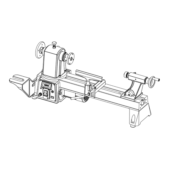
12 X 16" VARIABLE
SPEED WOOD LATHE
IMPORTANT:
NEED HELP? CONTACT US!
Have product questions? Need technical support?
Please feel free to contact us at:
800-232-1195
techsupport@wenproducts.com
WENPRODUCTS.COM
MODEL 34027
(M-F 8am-5pm CST)
4005911
Advertisement
Table of Contents

Related Manuals for Wen 34027


Summary of Contents for Wen 34027
- Page 1 4005911 IMPORTANT: Your new tool has been engineered and manufactured to WEN’s highest standards for dependability, ease of operation, and operator safety. When properly cared for, this product will supply you years of rugged, trouble-free performance. Pay close attention to the rules for safe operation, warnings, and cautions.
-
Page 2: Table Of Contents
Maintenance .................. 21 Troubleshooting Guide ..............22 Exploded View & Parts List ............23 Warranty Statement ............... 26 SPECIFICATIONS Model Number 34027 Motor 120 V, 60 Hz, 4.5A, S6 40% Swing Over Bed 12 in. Distance Between Centers 16 in. -
Page 3: Introduction
INTRODUCTION Thanks for purchasing the WEN Wood Lathe. We know you are excited to put your tool to work, but first, please take a moment to read through the manual. Safe operation of this tool requires that you read and understand this operator’s manual and all the labels affixed to the tool. This manual provides information regarding potential safety concerns, as well as helpful assembly and operating instructions for your tool. -
Page 4: General Safety Rules
GENERAL SAFETY RULES Safety is a combination of common sense, staying alert and knowing how your item works. SAVE THESE SAFETY INSTRUCTIONS. WARNING: Read and understand all warnings, cautions and operating instructions before using this tool. Failure to follow all instructions listed below may result in personal injury and tool damage. - Page 5 GENERAL SAFETY RULES 4. Prevent unintentional starting. Ensure the switch is in the off-position before connecting to power source and/or battery pack, picking up or carrying the tool. Carrying power tools with your finger on the switch or energizing power tools that have the switch on invites accidents. 5.
-
Page 6: Specific Safety Rules For The Wood Lathe
SPECIFIC RULES FOR THE WOOD LATHE WARNING: Do not let comfort or familiarity with the product replace strict adherence to product safety rules. Failure to follow the safety instructions may result in serious personal injury. 1. TOOL PURPOSE. This lathe is designed for turning wood or wood-like products only. Turning other materials could result in fire, injury, or damage to the workpiece. - Page 7 SPECIFIC RULES FOR THE WOOD LATHE 12. PREVENTING ACCIDENTAL STARTING. Make sure the power switch is in the OFF position prior to plugging in the machine. Always make sure the power switch is in the OFF position and the machine is unplugged when doing any cleaning, assembly, setup operations, or when not in use.
-
Page 8: Electrical Information
ELECTRICAL INFORMATION GROUNDING INSTRUCTIONS IN THE EVENT OF A MALFUNCTION OR BREAKDOWN, grounding provides the path of least resistance for an electric current and reduces the risk of electric shock. This tool is equipped with an electric cord that has an equipment grounding conductor and a grounding plug. The plug MUST be plugged into a matching outlet that is properly installed and grounded in accordance with ALL local codes and ordi- nances. -
Page 9: Know Your Wood Lathe
KNOW YOUR WOOD LATHE UNPACKING With the help of a friend or trustworthy foe, carefully remove the lathe from the packaging. Make sure to take out all contents and accessories. Do not discard the packaging until the lathe is completely as- sembled. -
Page 10: Assembly & Adjustments
ASSEMBLY & ADJUSTMENTS Before using the wood lathe, you must assemble the unit using the instructions in this section. Check your packing list against the diagram below. If any part is damaged or missing, please contact our cus- tomer service at (800) 232-1195, M-F 8-5 CST or email us at techsupport@wenproducts.com. PACKING LIST A. - Page 11 ASSEMBLY & ADJUSTMENTS INSTALLING SPINDLE LOCK Remove the spindle lock (Fig. 1 - 1) from the carton and install it onto the headstock with a wrench. WARNING: Disengage spindle lock before turning the machine on. The lock should be in its highest available position to prevent it from interfering with the rotation of the spindle (Fig.
- Page 12 ASSEMBLY & ADJUSTMENTS REMOVING THE FACE PLATE 1. Make sure the two set screws (Fig. 4 - 1 on p. 11) in the face plate (Fig. 4 - 2 on p. 11) have been backed out so they do not enter the central bore. Adjust them, if necessary, with the included hex wrench.
- Page 13 4. Adjust the hex nut until the tool rest base can be locked onto the back support. INSTALLING BED EXTENSION (SOLD SEPARATELY) The WEN 34027EX Wood Lathe Bed Extension is an op- tional accessory that can be purchased separately to extend the maximum length of the lathe’s capacity from 15.75 inches to 39.4 inches.
- Page 14 ASSEMBLY & ADJUSTMENTS TOOL REST ADJUSTMENTS Users can adjust the height, position and angle of the tool rest assembly. Loosen the locking lever (Fig. 14 - 1) on the tool rest base to slide the base forward and back or to adjust the angle of it.
-
Page 15: Operation
OPERATION OPERATING CONTROLS (FIG. 18) 1. Digital speed display - shows the current speed (RPM) of the spindle. 2. Protection Indicator - if the machine turns off and the protection indicator light begins to blink, it means that the motor was protected from overload. The workpiece may be too big or heavy for the current speed of the lathe. - Page 16 OPERATION TURNING TOOLS If possible, select only quality high-speed steel turning tools. High-speed steel tools hold an edge and last longer than ordinary carbon steel. As one becomes proficient in turning, a variety of spe- cialty tools for specific applications can be acquired. The following tools provide the basics for most wood-turning projects.
- Page 17 OPERATION SPINDLE TURNING Spindle turning takes place between the centers of the lathe. It requires a spur center in the headstock and a live center in the tailstock. A cup center rather than a cone center in the tailstock will often reduce the risk of splitting the stock. Stock for spindles should be straight grained and free of cracks, knots, nails and other defects.
- Page 18 OPERATION CUTTING TECHNIQUES Begin with a large roughing gouge. Place the tool on the tool rest with the heel of the tool on the surface to be cut. Slowly and gently raise the tool handle until the cutting edge comes into contact with the workpiece.
- Page 19 OPERATION SANDING - Leaving clean cuts will reduce the amount of sanding required. Move the tool rest out of the way, adjusting the lathe to a low speed. Being with find sandpaper (120 grit or finer), as coarser sandpaper will leave deep scratches and dull the features of the workpiece. Progress through each grit without skipping grits (as in, don’t jump from 120 grit to 220 grit).
- Page 20 OPERATION TO SHAPE THE OUTSIDE OF THE BOWL (FIG. 26) Odd shaped burls, crotches and other irregular shaped blanks require special preparation before mounting in a chuck or onto a face plate. Remove the bark, if there is any from what appears to be the cen- ter of the top of the workpiece.
-
Page 21: Maintenance
Any attempt to repair or replace electrical parts on this tool may be hazardous. Servicing of the tool must be performed by a qualified technician. When servicing, use only iden- tical WEN replacement parts. Use of other parts may be hazardous or induce product failure. ROUTINE INSPECTION Before each use, inspect the general condition of the tool. -
Page 22: Troubleshooting Guide
TROUBLESHOOTING GUIDE WARNING: Stop using the tool immediately if any of the following problems occur. Repairs and replacements should only be performed by an authorized technician. For any questions, please contact our customer service at (800) 232-1195, M-F 8-5 CST or email us at techsupport@ wenproducts.com. -
Page 23: Exploded View & Parts List
EXPLODED VIEW & PARTS LIST... - Page 24 EXPLODED VIEW & PARTS LIST Part No. Description Qty. Part No. Description Qty. 34027-001 Back Face Plate 3427-030-1 Handle 3427-002 Set Screw 3427-031 Set Screw 3427-003 Set Screw 3427-032-1 Tailstock Handle 3427-004 Screw Bushing 3427-033-1 Handle Screw 3427-005 Bearing 3427-034...
- Page 25 EXPLODED VIEW & PARTS LIST Part No. Description Qty. Part No. Description Qty. 3427-058 Set Screw 3427-087 Power Switch 3427-059 Indexing Disc 3427-088-1 Foot 3427-060 3427-089 Cord Clamp Speed Detection 3427-090 Pan Head Screw 3427-061 Plate 3427-091 Motor Pulley 3427-062 Magnet 3427-092 Set Screw...
-
Page 26: Warranty Statement
GREAT LAKES TECHNOLOGIES, LLC (“Seller”) warrants to the original purchaser only, that all WEN consumer power tools will be free from defects in material or workmanship for a period of two (2) years from date of purchase. Ninety days for all WEN products if the tool is used for professional or commercial use.
Need help?
Do you have a question about the 34027 and is the answer not in the manual?
Questions and answers