Advertisement
Quick Links
Your new tool has been engineered and manufactured to WEN's highest standards for dependability,
ease of operation, and operator safety. When properly cared for, this product will supply you years
of rugged, trouble-free performance. Pay close attention to the rules for safe operation, warnings,
and cautions. If you use your tool properly and for its intended purpose, you will enjoy years of
safe, reliable service.
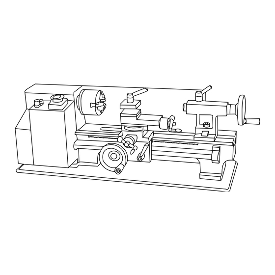
7 X 12 IN. METAL LATHE
IMPORTANT:
NEED HELP? CONTACT US!
Have product questions? Need technical support?
Please feel free to contact us at:
800-232-1195
techsupport@wenproducts.com
WENPRODUCTS.COM
VARIABLE SPEED
(M-F 8AM-5PM CST)
Model # 3455
bit.ly/wenvideo
Advertisement

Related Manuals for Wen 3455


Summary of Contents for Wen 3455
- Page 1 IMPORTANT: Your new tool has been engineered and manufactured to WEN’s highest standards for dependability, ease of operation, and operator safety. When properly cared for, this product will supply you years of rugged, trouble-free performance. Pay close attention to the rules for safe operation, warnings, and cautions.
-
Page 2: Table Of Contents
Know Your Lathe Assembly Operation Maintenance Troubleshooting Guide Exploded View & Parts List Warranty TECHNICAL DATA Model Number: 3455 110V, 60Hz, 4A Motor: 250W Output Power: 7 in. (180 mm) Swing Over Bed: 12 in. (300 mm) Distance Between Centers: Spindle Bore: .79 in. -
Page 3: General Safety Rules
GENERAL SAFETY RULES Safety is a combination of common sense, staying alert and knowing how your item works. SAVE THESE SAFE- TY INSTRUCTIONS. WARNING: To avoid mistakes and serious injury, do not plug in your tool until the following steps have been read and understood. 1. - Page 4 GENERAL SAFETY RULES 15. DO NOT OVERREACH. Keep proper footing and balance at all times. Wear oil-resistant rubber-soled foot- wear. Keep the floor clear of oil, scrap, and other debris. 16. MAINTAIN TOOLS PROPERLY. ALWAYS keep tools clean and in good working order. Follow instruc- tions for lubricating and changing accessories.
- Page 5 SPECIFIC RULES FOR LATHES 11. Always remove the key from the chuck jaws before operation. 12. Always wear a full face mask. If a tool or workpiece breaks off, it can create a hazard to users and onlookers. 13. Always use the right cutting tool. An improper tool could break or cause unwanted strain on the machine. 14.
-
Page 6: Electrical Information
ELECTRICAL INFORMATION GROUNDING INSTRUCTIONS IN THE EVENT OF A MALFUNCTION OR BREAKDOWN, grounding provides the path of least resistance for an electric current and reduces the risk of electric shock. This tool is equipped with an electric cord that has an equipment grounding conductor and a grounding plug. -
Page 7: Know Your Lathe
KNOW YOUR LATHE A - Running Gear Cover B - Lathe Control Panel C - Head Stock D - Spindle E - 3-Jaw Chuck F - Tool Post Lock G - Cross Slide Handle H - Compound Slide I - Quill J - Quill Lock K - Tailstock Hand Wheel L - Tailstock... -
Page 8: Assembly
KNOW YOUR LATHE BEHIND HEADSTOCK (FIG. B) A) : Allows the user to shift the spindle speed range from HIGH (0-2500 RPM) to LOW (0- 1100 RPM). DO NOT SHIFT FROM HIGH TO LOW WHILE THE LATHE IS RUNNING! B) LEAD SCREW DIRECTION LEVER: Change the direction of the lead screw rotation be- tween forward, reverse, and neutral. -
Page 9: Operation
OPERATION 18-3/4 in. MOUNTING THE LATHE (FIG. C) The lathe should be mounted on a strong, heavy workbench. Take the necessary precautions when moving the lathe. Assistance may be required. Bolt the machine firmly to the workbench us- 2-7/8 in. ing the tapped holes. - Page 10 OPERATION COMPOUND SLIDE The compound slide works similarly to the cross slide with a small han- dle and a scale with tick marks every 0.001”. The compound slide can be fed back and forth with this handle, similar to the cross slide. In addition it can also be rotated to an angle of your choice and fed back and forth along this angle.
- Page 11 ADJUSTMENTS TAILSTOCK The tailstock is located on the bed opposite of the headstock. It can be moved along the bed by loosening the 17 mm nut (Fig. E - Item E) and pushing the tailstock to the desired position. When it is in the desired spot, tighten the 17 mm nut to lock it in place.
- Page 12 OPERATION OFFSETTING YOUR TAILSTOCK WARNING: The tailstock comes from the factory properly aligned with the headstock. The tailstock can also be used in an offset position to help turn tapers on a work piece. Adjusting the tailstock into an offset position requires removing the tailstock from the bed and adjusting the offset screw on the bottom of the tailstock.
- Page 13 OPERATION GEAR TRAIN (FIG. F) WARNING: Before making any of these adjustments, turn off and unplug the lathe from its power source. The gear train is located on the headstock opposite the spindle. The drive gears are located under a cover secured by two socket head cap screws.
- Page 14 OPERATION CREATING NORMAL TURNING Before starting a turning, always plan your work ahead of time. Create a drawing or plan with all of the dimensions you desire for the workpiece. Make sure to have all the measuring tools you will need to double and triple check your cuts.
- Page 15 OPERATION (CONTINUED FROM LAST PAGE) To know the proper RPM will take some experience. Harder metals should use a slower RPM while softer can use a little faster RPM. If you are unsure, it is better to go slower than risk damage to the work, the cutting tool or the lathe by using too high of an RPM.
- Page 16 OPERATION BEVEL CUTTING In order to perform a bevel cut, it is necessary to use the compound slide as well as the cross slide. To align the compound slide for a bevel cut, align it to the proper angle following the procedure in the “Compound Slide” sec- tion on page 10.
- Page 17 OPERATION CHANGING THE JAWS IN YOUR CHUCK (FIG. G) 1. Make sure your lathe is turned off and unplugged. 2. Insert the chuck key into the square hole of the chuck. Turn the chuck key counterclockwise until all of the jaws come out of the chuck. 3.
- Page 18 OPERATION ADJUSTING THE GIBS (FIG. I) Although the factory setting should be fine, if you are having trouble feeding the compound or cross slide, you may want to adjust the COMPOUND gib screws. To adjust the gib you will need a 2mm and a 7mm hex SLIDE wrench.
-
Page 19: Maintenance
MAINTENANCE Before each use make sure to check all of the parts of the lathe for any loose bolts or connections. Leave the gear cover on to prevent chips from interfering with the geartrain. Make any adjustments to connections as necessary to ensure all the parts are connected and will stay together during operation. - Page 20 TROUBLESHOOTING PROBLEM CAUSE SOLUTION 1. Try and release the button or replace it. 1. Emergency button is stuck down. 2. Replace Fuse. 2. Fuse blown. 3. Check for any visible damage, and check with a 3. Damaged wiring. multimeter for correct wiring. 4.
- Page 21 TROUBLESHOOTING PROBLEM CAUSE SOLUTION Can’t remove 1. Quill isn’t retracted completely into 1. Turn the quill handle until the tool is forced out. center or chuck tailstock. 2. Always clean taper surfaces. Try and force out from tailstock 2. Debris in the quill. with WD40 and handle.
-
Page 22: Exploded View & Parts List
EXPLODED VIEW & PARTS LIST... - Page 23 EXPLODED VIEW & PARTS LIST No Part Number Description No Part Number Description 3455-001 Bed Way 3455-055 Washer M5 3455-002 3 Jaws Chuck 3455-056 Bush W/Key 3455-003 Spindle 3455-057 Gear 80T 3455-004 Set Screw M6 × 25 3455-058 Shaft 3455-005...
- Page 24 EXPLODED VIEW & PARTS LIST No Part Number Description No Part Number Description 3455-109 Bracket 3455-163 Variable Speed Control Knob 3455-110 Screw M4 × 12 3455-164 Toggle Switch 3455-111 Nut M18 3455-165 PC Board 3455-112 Label 3455-166 Screw M5×10 3455-113...
-
Page 25: Warranty
LIMITED TWO YEAR WARRANTY WEN Products is committed to build tools that are dependable for years. Our warranties are consistent with this commitment and our dedication to quality. LIMITED WARRANTY OF WEN CONSUMER POWER TOOLS PRODUCTS FOR HOME USE GREAT LAKES TECHNOLOGIES, LLC (“Seller”) warrants to the original purchaser only, that all WEN con- sumer power tools will be free from defects in material or workmanship for a period of two (2) years from date of purchase. - Page 26 THANKS FOR REMEMBERING...
Need help?
Do you have a question about the 3455 and is the answer not in the manual?
Questions and answers