Advertisement
184841
Your new tool has been engineered and manufactured to WEN's highest standards for dependability,
ease of operation, and operator safety. When properly cared for, this product will supply you years
of rugged, trouble-free performance. Pay close attention to the rules for safe operation, warnings,
and cautions. If you use your tool properly and for intended purpose, you will enjoy years of safe,
reliable service.
NOTICE: Please refer to wenproducts.com for the most up-to-date instruction manual.
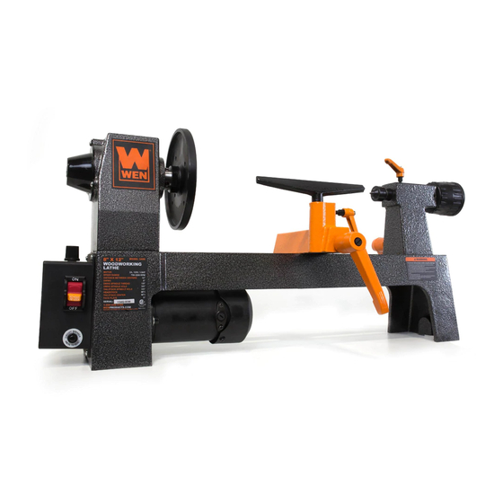
8-INCH WOOD LATHE
IMPORTANT:
NEED HELP? CONTACT US!
Have product questions? Need technical support?
Please feel free to contact us at:
800-232-1195
techsupport@wenproducts.com
WENPRODUCTS.COM
bit.ly/wenvideo
(M-F 8AM-5PM CST)
Advertisement
Table of Contents

Related Manuals for Wen 3420


Summary of Contents for Wen 3420
- Page 1 184841 IMPORTANT: Your new tool has been engineered and manufactured to WEN’s highest standards for dependability, ease of operation, and operator safety. When properly cared for, this product will supply you years of rugged, trouble-free performance. Pay close attention to the rules for safe operation, warnings, and cautions.
-
Page 2: Table Of Contents
Electrical Information Know Your Wood Lathe Assembly Adjustments Operation Maintenance Troubleshooting Guide Exploded View & Parts List Warranty TECHNICAL DATA 3420, 3420T Model Numbers: 120V, 60Hz, 2A Motor: Swing: 8 in. 12 in. Distance Between Centers: 750 to 3200 RPM Speeds: Spindle Taper: 1"... -
Page 3: General Safety Rules
GENERAL SAFETY RULES Safety is a combination of common sense, staying alert and knowing how your item works. SAVE THESE SAFE- TY INSTRUCTIONS. WARNING: To avoid mistakes and serious injury, do not plug in your tool until the following steps have been read and understood. 1. -
Page 4: Specific Safety Rules For Wood Lathes
GENERAL SAFETY RULES 15. DO NOT OVERREACH. Keep proper footing and balance at all times. Wear oil-resistant rubber-soled foot- wear. Keep the floor clear of oil, scrap, and other debris. 16. MAINTAIN TOOLS PROPERLY. ALWAYS keep tools clean and in good working order. Follow instruc- tions for lubricating and changing accessories. -
Page 5: Electrical Information
ELECTRICAL INFORMATION GROUNDING INSTRUCTIONS IN THE EVENT OF A MALFUNCTION OR BREAKDOWN, grounding provides the path of least resistance for an electric current and reduces the risk of electric shock. This tool is equipped with an electric cord that has an equipment grounding conductor and a grounding plug. -
Page 6: Know Your Wood Lathe
KNOW YOUR WOOD LATHE Power Switch Variable Speed Knob Circuit Breaker Headstock Tool Rest Locking Handle Quill Lock Motor Face Plate Tool Rest Live Center Tailstock Handwheel Tailstock Tailstock Locking Handle ASSEMBLY UNPACKING Carefully unpack the lathe and all its parts. Compare against the list below. Do not discard the carton or any packaging until the lathe is completely assembled. - Page 7 ASSEMBLY MOUNTING THE LATHE ON THE BENCHTOP Measure and mark three hole centers as shown in Figure A. Drill clearance holes through the bench top and position the lathe in place. Attach it securely with bolts (minimum of one inch) and washers (not included) from the underside of the bench top into the tapped holes in the bottom of the lathe’s frame.
- Page 8 ASSEMBLY INSTALLING THE DRIVE SPUR AND REVOLVING CENTER (FIG. F & G) Note: It is not necessary to remove the face plate in order to install the spur center. 1. Make sure the surfaces of both the spur center and the spindle are clean.
-
Page 9: Adjustments
ADJUSTMENTS ON/OFF SWITCH The ON/OFF switch (Fig. I - 1) controls the power to the unit. To start the lathe, move the switch into the ON position (flipped up). NOTE: This lathe features a gradual start up, meaning that the chuck will not start spinning until couple of mo- ments after the switch is turned ON, and will start spinning at a lower speed before gradually ramping up to its full RPM. - Page 10 ADJUSTMENTS TAILSTOCK 1. Move the tailstock (Fig. J - 5) by loosening the lock lever (Fig. J - 1) and pushing the tailstock to the desired position on the bed. Lock it back in place by tightening the lock lever again. 2.
-
Page 11: Operation
OPERATION TURNING TOOLS If possible, select only quality high-speed steel turning tools. High-speed steel tools hold an edge and last longer than ordinary carbon steel. As one becomes proficient in turning, a variety of specialty tools for specific applica- tions can be acquired. The following tools provide the basics for most woodturning projects. 2. - Page 12 OPERATION SPINDLE TURNING Spindle turning takes place between the centers of the lathe. It requires a spur center in the headstock and a live center in the tailstock. A cup center rather than a cone center in the tailstock will often reduce the risk of splitting the stock.
- Page 13 OPERATION CUTTING TECHNIQUES Begin with a large roughing gouge. Place the tool on the tool rest with the heel of the tool on the surface to be cut. Slowly and gently raise the tool handle until the cutting edge comes into contact with the workpiece. Beginning about 2 inches from the tailstock end of the workpiece, roll the flute of the tool (the hollowed-out portion) in the direction of the cut.
- Page 14 OPERATION Fig. U Fig. T Fig. W Fig. V MOUNTING ON THE FACE PLATE Use of the face plate is the most common for holding a block of wood for turning bowls and plates. This is an alternative option for workpieces with diameters that are greater than the 12-inch throat of the lathe. To mount the stock to the face plate, select a stock that is at least .2 inches (5 mm) larger than each dimension of the finished workpiece.
- Page 15 OPERATION TO SHAPE THE OUTSIDE OF THE BOWL (FIG. X) Odd shaped burls, crotches and other irregular shaped blanks require special preparation before mounting in a chuck or onto a face plate. Remove the bark, if there is any from what appears to be the center of the top of the workpiece.
-
Page 16: Maintenance
MAINTENANCE Keep your machine clean. At the end of each day, clean the machine. Wood contains moisture, meaning that sawdust and wood chips can cause rust if not removed. Regular oil attracts dust and dirt. Teflon lubricant tends to dry and has less of a tendency to accumulate dirt and saw dust. Periodically check that all nuts and bolts are tight. The drive belt should last for many years depending on usage, but it needs to be inspected regularly for cracks, cuts and general wear. -
Page 17: Exploded View & Parts List
EXPLODED VIEW & PARTS LIST Part No. Description Part No. Description 3420-001 3420-035 Power Cord 3420-002 Retaining Plate 3420-036 Switch Box Assembly 3420-003 Bolt 3420-037 Bolt 3420-004 Set Screw 3420-038 Bolt 3420-005 Hand Wheel 3420-039 Bolt 3420-006 Tailstock 3420-040 Motor Mount... - Page 18 EXPLODED VIEW & PARTS LIST...
- Page 19 LIMITED TWO YEAR WARRANTY WEN Products is committed to build tools that are dependable for years. Our warranties are consistent with this commitment and our dedication to quality. LIMITED WARRANTY OF WEN CONSUMER POWER TOOLS PRODUCTS FOR HOME USE GREAT LAKES TECHNOLOGIES, LLC (“Seller”) warrants to the original purchaser only, that all WEN con- sumer power tools will be free from defects in material or workmanship for a period of two (2) years from date of purchase.
- Page 20 THANKS FOR REMEMBERING...
Need help?
Do you have a question about the 3420 and is the answer not in the manual?
Questions and answers