Table of Contents
Advertisement
Advertisement
Table of Contents

Subscribe to Our Youtube Channel
Related Manuals for FAAC 541 3ph


Summary of Contents for FAAC 541 3ph
- Page 1 541 3ph 541 3ph...
-
Page 2: Warnings For The Installer
For non-EU countries, to obtain an adequate level of safety, the Standards mentioned above must be observed, in addition to national 21) Do not allow children or adults to stay near the product while it is legal regulations. operating. 9) FAAC is not responsible for failure to observe Good Technique in 22) Keep remote controls or other pulse generators away from children, to the construction of the closing elements to be motorised, or for any prevent the automated system from being activated involuntarily. deformation that may occur during use. -
Page 3: Technical Specifications
(in models for which it is supplied) make it possible to move the door 1:1.5 must be installed. in case of a power cut or malfunction. N.B. Force F can be measured with a dynamometer. It is not directly The 541 3ph automated systems was designed and built for indoor related to the weight of the door, but to its balance. and outdoor use. TECHNICAL SPECIFICATIONS Graph 1 Power supply (Vac 50-60Hz) 400 (+6 –10%) Electric motor 3 - phase induction 1450rpm Maximum absorbed power (W) -
Page 4: Preliminary Checks
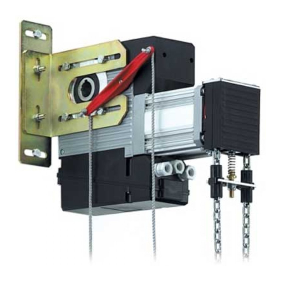
Operator Power take-off Securing plate Power cabling - 5x1.5 (4xPower supply 400Vac + Earth) Limit-switch unit Power cabling- 4x1. 5 (3xMotor power supply 400Vac + Earth) + 2x0.5 flashing lamp Winch (in models for which it is supplied) Low voltage cabling - controls for equipment + safety edge Equipment enclosure Low voltage cabling - 4x0,5 Rx photocells Release lever Low voltage cabling - 2x0.5 Tx photocells Key securing bushes Low voltage cabling - radio receiver Key ... - Page 5 5.1 OPERATOR WORK POSITION The operator - supplied with a chain-operated manual motion device - must be installed in the position shown in figure 4. In the absence of the winch, the operator can be installed in any position. If you wish to install the remote release control, first check that the release lever does not interfere with the operator’s external parts. The securing plate can be installed on any of the operator’s two sides. •Trace the position of the installation holes. •Remove the operator. •Carry out the securing preparation work. •Insert the first key securing bush and the key itself in the shaft (see fig.2 ref. 8 and 9). •Re-install the operator with the plate released. 5.3 INSTALLING THE OPERATOR •Secure the plate to the support, tighten the fastening screws on the operator to a maximum torque of 18Nm and insert the second key securing bush. •Release the operator with the appropriate lever. •Secure the two bushes after positioning them in contact with the •Fit the securing plate on the operator without tightening the screws. •Engage the power take-off on the drive shaft. operator’s power take-off. •Position the operator (see paragraph 5.1) and rest the plate on •Lock the operator. If you wish to weld the securing plate to the support, do the wel- the support (wall or metal structure) on which you have decided ding with the operator uninstalled, and protect the drive shaft in to secure it (see figure 6.).
- Page 6 5.4 WINCH ADJUSTMENT Unwind the supplied chain completely and join one of it its ends to the one already fitted to the winch, without cutting the service clip. Use one of the supplied links, selecting from those in steel (see figure 7 ref. A) or from those in plastic (see figure 7 ref.B). The plastic links must be assembled. Tighten the steel links accura- tely, to allow the chain to move perfectly, inside the winch. Cut the chain to size, without allowing the lower part of the ring it forms from touching the floor, and making sure that it is wound around itself (see figure 8). Assemble the other side of the chain, in the same way as in figure 7. Cut the service clip only when the chain is installed. Adjust the screw of the balancing spring (see figure 9) so that the winch support disappears completely inside the plastic enclosure (see figure 10). Check if the traction of just one of the chain sections causes the winch to engage and, if the winch returns to its idle position when it is released. Tighten the securing nut and make sure that operator activation is not inhibited or interrupted by the tripping of the winch safety microswitch. We advise you to provide an anchoring point for the lower part of the chain so that it cannot hinder the transit of people or of ope- rating means. Apply the sticker indicating the opening and closing directions, in a clearly visible way. If you are using the chain extension kit, replace the balancing Fig.
- Page 7 5.7 IDENTIFYING ROTATION DIRECTION (operator with 844T 5.6 ADJUSTMENT OF LIMIT-SWITCH UNIT equipment) The procedure for adjusting the closing and opening limit- Figure 12 shows rotation directions Dir1 and Dir2. Motion in Dir1 direction is switch is as follows: stopped by FC1 and motion in Dir2 direction by FC2. Consequently, if, for Completely close the industrial sectional door. example, Dir2 is the rotation direction causing the door to close, FC2 deter- Using trimmer 1, with the arrow facing down (closing), turn mines the stop closing point and FC1 determines the opening stop point. clockwise to + or anti-clockwise to - until The OPEN command is normally associated with Dir1 motion - consult the the closing limit-switch is activated. equipment instructions if the rotation directions have to be reversed. Then set the industrial sectional door in opening position. The stop spring of the ring-nuts activating the limit-switches, is kept lifted up Using trimmer 1, with the arrow facing up (opening), turn by the square - the latter must not be removed until the door stop points clockwise to + or anti-clockwise to - until are adjusted. the opening limit-switch is activated (see fig. 11). Note for fine adjustment: the “+” symbol indicates backing away of the activator from the microswitch and therefore a longer stroke; the “-” symbol, on the contrary, indicates its approach and consequently a shorter stroke. Final check of the open and closed positions. Manually move the door in open and close position. Ensure that the operator actually reaches the desired positions when opening and closing. If this does not occur, correct the limit-switch positions using trimmer 1.
- Page 8 Opening Reduce stroke Increase stroke Fig. 13 Closing Reduce stroke Increase stroke Fig. 14 5.8 INSTALLING THE REMOTE RELEASE LEVER Carry out the operations with the door closed. Cut the drive ropes to measure and assemble them with the lever and knobs (see figure 15), bearing in mind that the green one must act on the lever’s short arm. In figure 16 , the two side views show the position of the lever with locked operator, and the relevant positions of the release ropes (with red knob) and locking ropes (with green knob). Fit the lever and make sure that it reaches the travel limits in the two directions, at an inclination of about 45-50°. Fit the lever fixing screw. Make sure that the remote manoeuvre is correct and that, when the operator is in locked position, it is not prevented from operating by the release safety microswitch.
-
Page 9: Electrical System
7. START-UP When you have carried out all the electrical connections, locked the operator, and checked that the door cannot be moved by hand, power up the system. If the operator is supplied with a winch, fix - in the immediate vicinity of the chain - the sticker indicating the traction directions for the opening and closing manual manoeuvres. 7.1 541 3ph WITH 844T EQUIPMENT Program the unit, following the instructions of the 844T unit. 8. MAINTENANCE Maintenance: check at least every 6 months the efficiency of the system, particularly the efficiency of the safety devices (including, where foreseen, the operator thrust force) and of the release devices. -
Page 10: General Safety Regulations
541 3ph AUTOMATED SYSTEMS winch (for models with which it is supplied). Read the instructions carefully before using the product and store Electric command is disabled during the manual manoeuvre or them for future use. when the operator is released. The warning-light, where supplied, indicates that the door is cur- rently moving. GENERAL SAFETY REGULATIONS If correctly installed and used, 541 3ph automated systems ensure MANUAL OPERATION (541 3ph with winch) a high degree of safety. Some simple rules on behaviour can prevent accidental trouble: - Do not, under any circumstances, stand under the sectional door. If the door has to be activated and the automated system is - Do not allow children, persons or things to stand near the automa- inactive due to a power-cut or malfunction, the door opening and ted systems, especially while they are operating. closing manoeuvres can be done by hand, by using the chain- - Keep remote-controls, or other pulse generators that could open operated winch. Check the indicator sign to see which branch of... - Page 12 Les descriptions et les illustrations du présent manuel sont fournies à titre indicatif. FAAC se réserve le droit d’ap- porter à tout moment les modifications qu’elle jugera utiles sur ce produit tout en conservant les caractéristiques essentielles, sans devoir pour autant mettre à...
Need help?
Do you have a question about the 541 3ph and is the answer not in the manual?
Questions and answers