
Related Manuals for SIEB & MEYER SD2B


Summary of Contents for SIEB & MEYER SD2B
- Page 1 SIEB & MEYER Drive Amplifier SD2B / SD2B plus Hardware Description P-TD-0000312.8 2019-09-09...
- Page 2 SIEB & MEYER Asia Co. Ltd. 4 Fl, No. 532, Sec. 1 Min-Sheng N. Road Kwei-Shan Hsiang 333 Tao-Yuan Hsien Taiwan Phone: +886 3 311 5560 Fax: +886 3 322 1224 smasia@ms42.hinet.net http://www.sieb-meyer.com Drive Amplifier SD2B / SD2B plus - Hardware Description...
- Page 3 Device variant SD2B Device variant SD2B plus Connector Pin Assignment Connection Examples Status Display and Error Messages General Information Regarding the Wiring Electric Performance Dimensioning Safety Circuit / Restart Lock (STO) Appendix Index Drive Amplifier SD2B / SD2B plus - Hardware Description...
- Page 4 Chapter Overview Drive Amplifier SD2B / SD2B plus - Hardware Description...
-
Page 5: Table Of Contents
Operation of the Terminal Connectors ............8.1.1 Spring-cage Connection ..................8.1.2 Push-in Technology ....................ID switch ....................X2 – Motor Connection ................X4 – DC Power Supply ................X6 – Logic Supply ..................Drive Amplifier SD2B / SD2B plus - Hardware Description... - Page 6 General Information Regarding the Wiring ...... 11.1 Cable Requirements ................. 11.1.1 Motor Cable ......................Electric Performance Dimensioning ........ 12.1 Components ....................12.1.1 Output Stage ......................12.1.2 Power Supply ......................12.1.3 Motor ........................Drive Amplifier SD2B / SD2B plus - Hardware Description...
- Page 7 Appendix ................. 14.A Specification of Device Firmware .............. 14.B Manufacturers ................... 14.B.1 SIEB & MEYER Accessories ................14.B.1.1 Connectors of the Series SD2B / SD2B plus ............14.B.1.2 Blocking Diode ...................... 14.B.1.3 Operating Terminal ....................14.B.1.4 USB>RS232/485 Converter 050201 ..............14.B.2 Phoenix Contact ....................
- Page 8 Content Drive Amplifier SD2B / SD2B plus - Hardware Description...
-
Page 9: About This Manual
Indicates a hazardous situation which, if not avoided, may result in prop‐ erty damage. Risk symbols Risk symbol Description General hazardous situation Risk of injury due to electric shock Risk of injury due to hot surfaces Drive Amplifier SD2B / SD2B plus - Hardware Description... -
Page 10: Illustration Of General Notices
Output Signal Switching Device pulse amplitude modulation pulse width modulation SERVO servo control safety function: Safe Torque Off sensorless vector control V/f Characteristic Curve voltage at the common collector VECTOR vector control Drive Amplifier SD2B / SD2B plus - Hardware Description... -
Page 11: General Information
General Information General Information This manual describes the drive amplifiers of the series SD2B / SD2B plus. These devices allow operation of high-dynamic servo motors as well as synchronous and asynchronous high-frequency spindles. The devices are equipped with interfaces for different sensor systems and allow the operation of motors with Hall and incremental sensors. - Page 12 General Information Drive Amplifier SD2B / SD2B plus - Hardware Description...
-
Page 13: Safety Instructions
DIN VDE 0110 as well as the national accident prevention regulations shall be considered! When installing feed-in systems adhere to all applicable regulations, special safety instructions and technical connection conditions of the local DSO. Drive Amplifier SD2B / SD2B plus - Hardware Description... -
Page 14: Appropriate Use
"EMC Guidelines" means that the machine manufacturer has to carry out new meas‐ urements to comply with the regulations. SIEB & MEYER devices meet the requirements of the Low-Voltage Directive 2014/35/EU. The harmonized standards of DIN EN 50178 and DIN EN 60204-1 in Drive Amplifier SD2B / SD2B plus - Hardware Description... -
Page 15: Reasonably Foreseeable Misuse
Avoid improper mechanical load of the device. The following points must especially be taken into consideration: ▶ Protect the device against mechanical damage (max. acceleration = 40 m/s²). ▶ Protect the device against dirt and humidity. Drive Amplifier SD2B / SD2B plus - Hardware Description... -
Page 16: Installation
Devices with air cooling only can be loaded to their maximum up to a height of 1000 m above MSL (3281 ft above MSL). For an operation in areas higher than Drive Amplifier SD2B / SD2B plus - Hardware Description... -
Page 17: Electrical Connection
The electrical installation must be carried out according to the relevant electrical codes (e.g. appropriate wire gauges, fuse protection and connections of ground conductors must be considered). Drive Amplifier SD2B / SD2B plus - Hardware Description... -
Page 18: Operation
During the operation of an installation with open doors or removed covers, persons may seriously be injured by moving machine parts. Keep the doors closed during the operation and do not remove covers. Drive Amplifier SD2B / SD2B plus - Hardware Description... -
Page 19: Maintenance
SJ/T 11364-2014 (China RoHS 2 on the restriction of the use of hazardous substances in electrical and electronic equipment) SIEB & MEYER products labeled with the symbol above do not exceed the limits of the directive SJ/T 11364-2014 for hazardous substances. Drive Amplifier SD2B / SD2B plus - Hardware Description... -
Page 20: Legal Warranty
Due diligence of the machine manufacturer A first programming carried out by SIEB & MEYER does not release the machine manufacturer from his duty to check the programmed values for correctness. Drive Amplifier SD2B / SD2B plus - Hardware Description... -
Page 21: Unit Assembly Complying Emc
▶ safety-relevant aspects ▶ extracts from the EMC product standard ▶ possibilities for the connection to different supply system types Availability: ▶ PDF file under www.sieb-meyer.de/downloads.html Drive Amplifier SD2B / SD2B plus - Hardware Description... - Page 22 Unit Assembly Complying EMC Drive Amplifier SD2B / SD2B plus - Hardware Description...
-
Page 23: Drive Amplifier Sd2B / Sd2B Plus
Indicates the version of the hardware; if no version is existent, 0.000 is indicated here IP Code Indicates the level of protection of the device against touching or intrusion of solid objects (1st digit) and water ingress (2nd digit) QA label Drive Amplifier SD2B / SD2B plus - Hardware Description... -
Page 24: Device Designation
SIEB & MEYER to check whether the devices are compatible or not. In addition the device version indicates the update capability of the internal device soft‐ ware, e.g. BIOS, FPGA or Firmware. Drive Amplifier SD2B / SD2B plus - Hardware Description... -
Page 25: Functional Overview Of The Device Variants
HSBLOCK / FPAM PAM (Hall) – – FPAM (sensorless) – – HSPWM – – VF-PWM ✔ (up to 2 kHz) ✔ (up to 2 kHz) HSPAM / VF VF-PAM – – Drive Amplifier SD2B / SD2B plus - Hardware Description... - Page 26 Drive Amplifier SD2B / SD2B plus Drive Amplifier SD2B / SD2B plus - Hardware Description...
-
Page 27: Device Variant Sd2B
Take measures to protect the device against contamination, in particular due to conductive or aggressive materials. Contamination can cause malfunctions and short- circuits. Drive Amplifier SD2B / SD2B plus - Hardware Description... -
Page 28: Block Diagram
Device variant SD2B Block Diagram The following block diagram shows the functional groups and connection options of the device. Fig. 3: Block diagram SD2B Drive Amplifier SD2B / SD2B plus - Hardware Description... -
Page 29: Dimensions/Mounting
Device variant SD2B Dimensions/Mounting Fig. 4: Dimensions SD2B in mm (inch) ▶ vertical mounting at spacers and heat sink: 4 M3 bolts ▶ wall mounting at heat sink: 2 M4 bolts Drive Amplifier SD2B / SD2B plus - Hardware Description... -
Page 30: Technical Data
: from device version 4.100 and software version 1.14.100 onwards Adjustable via software For SD2B / SD2B plus with a device version < 4.100 the column 80 V applies. Device version 4.0xx can be reconfigured to reach version 4.100, see “TIE_SD2B_AdjustableSupplyVoltage.pdf”. -
Page 31: Connectors
(see connection example page 48). Connectors Fig. 5: Connectors of SD2B (top view) You can order the appropriate connector kit for SD2B at SIEB & MEYER (article No. 32299576). Drive Amplifier SD2B / SD2B plus - Hardware Description... - Page 32 Device variant SD2B Drive Amplifier SD2B / SD2B plus - Hardware Description...
-
Page 33: Device Variant Sd2B Plus
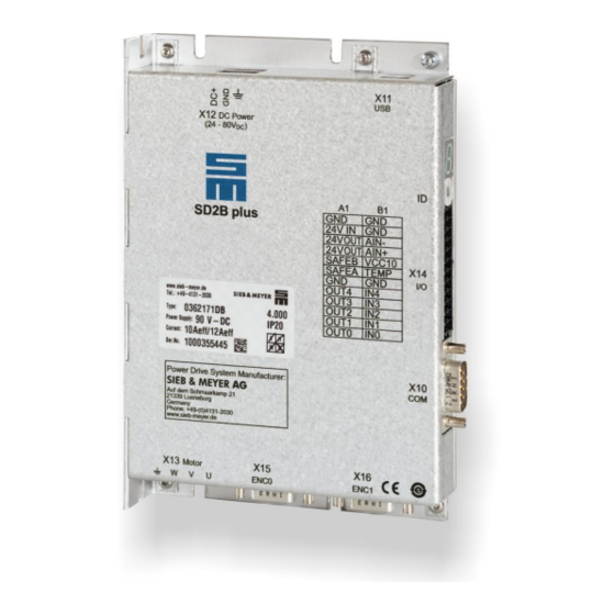
Device variant SD2B plus Device variant SD2B plus Fig. 6: Device view of SD2B plus (0362171DB) Block Diagram The following block diagram shows the functional groups and connection options of the device. Drive Amplifier SD2B / SD2B plus - Hardware Description... - Page 34 Device variant SD2B plus Fig. 7: Block diagram SD2B plus Drive Amplifier SD2B / SD2B plus - Hardware Description...
-
Page 35: Dimensions/Mounting
The mounting surface must be able to dissipate a heat output of 25 W at a housing temperature of 60 °C for each device. ▶ With vertical mounting several device can be mounted next to each other without any space in-between. Fig. 9: Mounting options Drive Amplifier SD2B / SD2B plus - Hardware Description... -
Page 36: Technical Data
Minimum size of cooling surface: 6 dm² (natural convection) Admissible voltage ripple: max. 10 % The logic voltage is necessary to maintain the error messages. It is protected by an electronic fuse on the device. Drive Amplifier SD2B / SD2B plus - Hardware Description... -
Page 37: Connectors
Device variant SD2B plus Connectors Fig. 10: Connectors of SD2B plus You can order the appropriate connector kit for SD2B plus at SIEB & MEYER (article No. 32299587). Drive Amplifier SD2B / SD2B plus - Hardware Description... - Page 38 Device variant SD2B plus Drive Amplifier SD2B / SD2B plus - Hardware Description...
-
Page 39: Connector Pin Assignment
16 adresses are available: 0, 1, 2, 3, 4, 5, 6, 7, 8, 9, A, B, C, D, E, F. The addresses of several devices in a system must be different from each other to ensure that they can be identified by the software. Drive Amplifier SD2B / SD2B plus - Hardware Description... -
Page 40: X2 - Motor Connection
Tightening torque: 0.5 to 0.6 Nm NOTICE Wiring error To prevent wiring errors and subsequent damage to the device you must always wire all pins (incl. pin 2 / DC−) with adequate conductor cross-section. Drive Amplifier SD2B / SD2B plus - Hardware Description... -
Page 41: X6 - Logic Supply
X9 – Inputs/Outputs The available functions of the inputs and outputs are different depending on the drive drive‐ function. You must set the desired function for each input/output in the software master2 . Drive Amplifier SD2B / SD2B plus - Hardware Description... -
Page 42: X10 - Com1 / Operating Terminal
CAN_L CAN_L Ground Receive data 2 Transmit data 2 CAN_H CAN_H Ground Stud bolt flange: max. tightening torque = 0.7 Nm Related topics Connection examples: "X10 – Bus Connection", page 51 Drive Amplifier SD2B / SD2B plus - Hardware Description... -
Page 43: X11 - Usb
To prevent wiring errors and subsequent damage to the device you must always wire all pins (incl. pin 2 / DC−) with adequate conductor cross-section. Related topics Connection example: "X12/X14 – DC Power Supply Unit", page 53 Drive Amplifier SD2B / SD2B plus - Hardware Description... -
Page 44: X13 - Motor Connection
Startup peak current per device can exceed 8 A/24 V during the first 2 ms. Ground OUT4 Digital output OUT3 Digital output OUT2 Digital output OUT1 Digital output OUT0 Digital output Ground Ground Drive Amplifier SD2B / SD2B plus - Hardware Description... -
Page 45: X15 - Encoder 0
Meaning Track A+ Track A- Zero pulse+ Zero pulse- Ground Track B+ Track B- VCC_ENC 5.3 V supply voltage Measuring system error Stud bolt flange: max. tightening torque = 0.7 Nm Drive Amplifier SD2B / SD2B plus - Hardware Description... -
Page 46: X16 - Encoder 1 / Encoder Emulation
Connection example: "X15, X16 – Incremental Encoder with TTL Signals", page 56 Connection example: "Encoder Emulation", page 57 Connection example: "Hall Sensor 5.3 V", page 58 Connection example: "PULSE IN 5.3 V", page 58 Drive Amplifier SD2B / SD2B plus - Hardware Description... -
Page 47: Connection Examples
▶ connect the ground terminal of the motor connector to the central ground point of the machine. Consider the following with regard to shielding: Always use shielded motor cables! Drive Amplifier SD2B / SD2B plus - Hardware Description... -
Page 48: X4 - Decoupling Of The Main Voltage
SD2B for main and logic supply. Setup 1: 24 V logic and main voltage supply (one power supply unit) Setup 2: 24 V logic supply and 48 V main voltage supply (two power supply units) Drive Amplifier SD2B / SD2B plus - Hardware Description... -
Page 49: X9 - Inputs/Outputs
The meanings of the digital inputs can be defined by parameters. 9.4.2 Digital Outputs The output driver can operate as low-side driver or as high-side driver. You can set the drivemaster2 . desired driver type in the software Drive Amplifier SD2B / SD2B plus - Hardware Description... -
Page 50: Analog Input
The NTC/PTC behavior of the monitoring is defined in the software (motor para‐ meters). The controller is deactivated as soon as the critical motor temperature is reached. You can configure “None”, “PTC / Thermo switch”, “NTC”, “KTY84/130”, “KTY83/122” and “PT1000”. Drive Amplifier SD2B / SD2B plus - Hardware Description... -
Page 51: X10 - Bus Connection
X10 – Bus Connection 9.6.1 COM1 – RS232 If you connect X10 to a standard RS232 interface of a PC (9-pole male submin D connector), the used cable must look like this: Drive Amplifier SD2B / SD2B plus - Hardware Description... -
Page 52: Can Bus
The limiting value is between 32 and 100 bus nodes. depending on the used cable and transmission rate. For further information on the maximum number of bus nodes refer to the document “CAN Physical Layer” by the user organization CiA e. V. Drive Amplifier SD2B / SD2B plus - Hardware Description... -
Page 53: X12/X14 - Dc Power Supply Unit
(> 20 mA), see connection example section 9.8.2 "Digital Outputs", page 54 X14 – In/Out / STO 9.8.1 Digital Inputs The meanings of the digital inputs can be defined by parameters. Drive Amplifier SD2B / SD2B plus - Hardware Description... -
Page 54: Digital Outputs
Connection Examples 9.8.2 Digital Outputs The output driver can operate as low-side driver or as high-side driver. You can set the drivemaster2 . desired driver type in the software Drive Amplifier SD2B / SD2B plus - Hardware Description... -
Page 55: Analog Input
Can also be connected to potentiometer (500 Ω – 5 kΩ) 9.8.4 safety circuit (STO) See also chapter 13 "Safety Circuit / Restart Lock (STO)", page 9.8.4.1 Wiring with OSSD OSSD = Output Signal Switching Device Drive Amplifier SD2B / SD2B plus - Hardware Description... -
Page 56: Wiring Without Ossd
Connection Examples 9.8.4.2 Wiring without OSSD OSSD = Output Signal Switching Device X15, X16 – Incremental Encoder with TTL Signals Encoder signals: 5V Drive Amplifier SD2B / SD2B plus - Hardware Description... -
Page 57: X16 - Enc1/Emu
Connection Examples 9.10 X16 – ENC1/EMU 9.10.1 Encoder Emulation The transmission meets the requirements of the standard TIA/EIA-422-B with a voltage differential of at least. ±0.9 V. Drive Amplifier SD2B / SD2B plus - Hardware Description... -
Page 58: Hall Sensor 5.3
Connection Examples 9.10.2 Hall Sensor 5.3 V 9.10.3 PULSE IN 5.3 V Drive Amplifier SD2B / SD2B plus - Hardware Description... -
Page 59: Status Display And Error Messages
Code Description Ready to switch on Controller active Controller active, controller is limited / PI limit Mains 'Ready for operation' not present yet Boot loader active (during boot / software load) Drive Amplifier SD2B / SD2B plus - Hardware Description... -
Page 60: List Of Drive Error Messages
Faulty configuration of mailbox, Configuration error PDO, watchdog or synchronization Control channel of bus system NMT error 2, 3, 4 was not active during switch-on (pre-operational) Faulty drive address Addressing error Drive Amplifier SD2B / SD2B plus - Hardware Description... - Page 61 DC link was not precharged to the (0x522) mains voltage too low nected from mains. minimum voltage level in the set (1314 time period; mains voltage connected to the short-circuited DC link Drive Amplifier SD2B / SD2B plus - Hardware Description...
- Page 62 For ▶ HSBLOCK details refer to the corresponding setup ▶ FPAM instructions. ▶ ▶ HSPWM ▶ 1, 2, 3 4 EMF monitoring Flux monitoring Over current monitoring Drive Amplifier SD2B / SD2B plus - Hardware Description...
- Page 63 Output Frequency is parame‐ terized incorrectly ▶ OSSD signals are set incor‐ rectly Communication error Safety function SFM/SLOF: between DSP and safety communication between DSP and controller safety controller is disturbed Drive Amplifier SD2B / SD2B plus - Hardware Description...
-
Page 64: List Of Warning Messages
Motor temperature greater than parameterized warning threshold W07 DC link voltage greater than parameterized warning threshold W08 DC link voltage less than parameterized warning threshold W09 Speed controller in current limitation / PI limit Drive Amplifier SD2B / SD2B plus - Hardware Description... -
Page 65: Message Of The Quick Stop Functions
Software positioning error "Positive limit" Bus system "Quick stop" (The quick stop bit is set to 0) Digital input "Negative limit switch" Digital input "Positive limit switch" Digital input "Speed Enable" Drive Amplifier SD2B / SD2B plus - Hardware Description... - Page 66 Status Display and Error Messages Drive Amplifier SD2B / SD2B plus - Hardware Description...
-
Page 67: General Information Regarding The Wiring
Admissible current I [A] section A [mm²] E wiring (3 cable leads) F wiring (3 cable leads) B2 wiring 0.75 10.4 – 1.00 12.4 – 1.50 12.2 – 2.50 16.5 – – Drive Amplifier SD2B / SD2B plus - Hardware Description... - Page 68 ISO and AWG/MCM values are shown in the following table. Standardized cross-sections of round conductors: ISO cross-section [mm²] AWG/MCM Value Equivalent cross-section [mm²] 0.205 – 0.324 0.519 0.75 0.82 Drive Amplifier SD2B / SD2B plus - Hardware Description...
-
Page 69: Motor Cable
▶ connect the ground terminal of the motor connector to the central ground point of the machine. Consider the following with regard to shielding: Always use shielded motor cables! Drive Amplifier SD2B / SD2B plus - Hardware Description... - Page 70 The maximum admissible length of the motor cable is 100 m. The capacity must not exceed 5.2 nF. Example: If the cable capacity is 0.26 nF per meter, the maximum admissible length of the motor cable is 20 m. Drive Amplifier SD2B / SD2B plus - Hardware Description...
-
Page 71: Electric Performance Dimensioning
The power supply is specified by the following details: Voltage range The maximum supply voltage is limited by the used transistors, diodes and capacitors and the minimum space between the strip conductors. Drive Amplifier SD2B / SD2B plus - Hardware Description... -
Page 72: Motor
(see “Settings ÿ Program settings ÿ View”). When switching the view, the existing values are automatically converted into the new unit. The default setting is the RMS value. Drive Amplifier SD2B / SD2B plus - Hardware Description... - Page 73 Due to the low inductance value motors in tightening systems are operated at a high pulse with modulation frequency (PWM frequency 16 kHz) to keep the current ripple as small as possible. Drive Amplifier SD2B / SD2B plus - Hardware Description...
-
Page 74: Power Consumption Of A Drive
The examples clearly show that the expected motion profile must be considered when dimensioning the power supply unit. An exact dimensioning can only be achieved by integrating the motion profile. The same applies for conceiving the output stage and the motor. Drive Amplifier SD2B / SD2B plus - Hardware Description... -
Page 75: Safety Circuit / Restart Lock (Sto)
The advantage of this circuit is that a single drive can be locked safely in an installation with several drives while other drives remain in operation. Besides, a drive can be locked without having to charge the DC link electrolytic capacitor at a new restart. Drive Amplifier SD2B / SD2B plus - Hardware Description... -
Page 76: Functional Description Of The Restart Lock
(SIL 4). The TÜV checked safety circuit is controlled by the OSSD1+2 signal or via one or several emergency stop switch devices. See also section 13.2 "Wiring Example", page 77 Drive Amplifier SD2B / SD2B plus - Hardware Description... -
Page 77: Wiring Example
(according to stop function category 0+1), which meets the safety requirements according to SIL 3 (EN ISO 13849-1). This circuit allows connecting several emergency stop devices in parallel, which are permanently monitored. Drive Amplifier SD2B / SD2B plus - Hardware Description... -
Page 78: Requirements And Standards
Performance Level e ▶ according to EN 61508-1:2010 and EN 61800-5-2:2014-06 ─ PFH = 0 ─ SFF = 100 % (if there are PFH values, then SFF<100%) ─ HFT = 0 Drive Amplifier SD2B / SD2B plus - Hardware Description... - Page 79 When connected appropriately, the safety concept K1 does not supply any share of dangerous, undetected errors in the safety chain for the function STO. Thus the stop function 0+1 according to EN 60204-1:2007-6 is realized. Drive Amplifier SD2B / SD2B plus - Hardware Description...
- Page 80 Safety Circuit / Restart Lock (STO) Drive Amplifier SD2B / SD2B plus - Hardware Description...
-
Page 81: Appendix
Appendix Appendix 14.A Specification of Device Firmware For the drive amplifiers of the series SD2B / SD2B plus the following firmware is avail‐ able at present. Firmware F11001vxxxxx UF / SVC SERVO / VECTOR ✔ Sensorless vector control (SVC), synchronous ✔... - Page 82 Appendix 14.A Drive Amplifier SD2B / SD2B plus - Hardware Description...
-
Page 83: B Manufacturers
Manufacturers 14.B.1 SIEB & MEYER Accessories In the following you find all accessories for SD2B / SD2B plus that you can order at SIEB & MEYER. Consider the information on accessories suitable for your device in the tech‐ nical manual. -
Page 84: Phoenix Contact
Appendix B: Manufacturers 14.B.2 Phoenix Contact http://www.phoenixcontact.com Order key for Phoenix connectors Labeled connectors can be ordered at SIEB & MEYER. 14.B Drive Amplifier SD2B / SD2B plus - Hardware Description... -
Page 85: Index
Spring-cage connection Status display STO (Safe Torque Off) Firmware Functional overview SD2B / SD2B plus Technical data SD2B Technical data SD2B plus Type plate ID switch USB>RS232/485 converter Line cross-sections Warning messages Drive Amplifier SD2B / SD2B plus - Hardware Description... - Page 86 X11 – USB X12 – DC input X13 – motor X14 – IN/OUT X15 – ENC0 X16 – ENC1/EMU X2 – motor X4 – DC input X6 – Logic X9– inputs/outputs Drive Amplifier SD2B / SD2B plus - Hardware Description...
Need help?
Do you have a question about the SD2B and is the answer not in the manual?
Questions and answers