
Related Manuals for SIEB & MEYER 0362171DA1 Series


Summary of Contents for SIEB & MEYER 0362171DA1 Series
- Page 1 SIEB & MEYER Drive Amplifier SD2B plus 0362171DA1xxxx, 0362171DB1xxxx Hardware Description D-00000262 2020-11-04...
- Page 2 Copyright Original instructions, Copyright © 2020 SIEB & MEYER AG. All Rights Reserved. This manual or extracts thereof may only be copied with the explicit authorization by SIEB & MEYER AG. Trademarks All product, font and company names mentioned in this manual may be trademarks or registered trademarks of their respective companies.
-
Page 3: Table Of Contents
Table of Contents About this Manual..............Illustration of Warnings..................5 Abbreviations..................... General Information.............. Approval for the Markets in USA and Canada........... NRTL Requirements..................Safety Instructions..............10 Standards and Regulations................10 Working on the Device..................10 Appropriate Use....................Reasonably Foreseeable Misuse..............12 Transport and Storage..................Installation......................13 Electrical Connection.................. - Page 4 Table of Contents 7.4.3 Analog Input......................... 7.4.4 Safety Circuit (STO)..................... 7.4.4.1 Wiring with OSSD......................37 7.4.4.2 Wiring without OSSD....................37 X14 – Temperature Sensor of the Motor............38 X15, X16 – Incremental Encoders with TTL Signals........X15 – RENISHAW Biss C Mode (Unidirectional)..........40 X16 –...
-
Page 5: About This Manual
About this Manual About this Manual This chapter descirbes symbols, signal words and abbreviations used in this manual. Note You can download more documentation from the SIEB & MEYER website under http:// www.sieb-meyer.de/downloads.html. Illustration of Warnings In this manual, the warnings listed below are used. Depending on their degree of risk, the risk levels listed below exist: DANGER Imminent risk of injury... - Page 6 About this Manual OSSD output signal switching device pulse amplitude modulation pulse width modulation SERVO servo control safety function: Safe Torque Off sensorless vector control V/f Characteristic Curve voltage at the common collector VECTOR vector control Drive Amplifier SD2B plus - 0362171DA1xxxx, 0362171DB1xxxx...
-
Page 7: General Information
General Information General Information This manual describes the drive amplifiers of the series SD2B plus. These devices al- low operation of high-dynamic servo motors as well as synchronous and asynchronous high-frequency spindles. The devices are equipped with interfaces for different sensor systems and allow the op- eration of motors with Hall and incremental sensors. -
Page 8: Nrtl Requirements
General Information TÜV SÜD Product Service is an NRTL approved by OSHA and undertakes product cer- tifications for industrial controls, electric drives and other products. The following links lists the approved NRTL laboratories: https://www.osha.gov/dts/otpca/nrtl/nrtllist.html The tested devices are labeled with the following symbol: The device series SD2B plus is tested accoring to the harmonized standard IEC / UL 61800-5-1: „Standard for Adjustable Speed Electrical Power Drive Systems - Part 5-1: Safety Requirements - Electrical Thermal and Energy‟... - Page 9 General Information ▸ Only valid for UL 61800-5-1, IEC 61800-5-1 and UL-1004-1. Technical Considerations: ▸ The equipment under test was tested for use at the maximum ambient temperature permitted by the manufacturer's specification of: +40 °C. ▸ The maximum operation altitude of the equipment is specified for 1000 m. ▸...
-
Page 10: Safety Instructions
Safety Instructions Safety Instructions Note These safety instructions include important information regarding your safety and must be observed during installation and operation of SIEB & MEYER devices. Read them carefully and keep them for later use. Also adhere to safety instructions in the product documentation and on the device. Standards and Regulations SIEB &... -
Page 11: Appropriate Use
Safety Instructions DANGER Risk of serious damage to property and personal injury may occur: - when covers are removed illegally - due to improper use - when either the installation or the operation is incorrect → Observe the corresponding notes and information in the product doc- umentation of your device. -
Page 12: Reasonably Foreseeable Misuse
Safety Instructions Technical data and the connection specification can be found in the respective product documents. Line filters If adequate interference suppression measures are applied and the appropriate use in industrial applications of the device is ensured SIEB & MEYER devices comply with the Directive EMC Directive 2014/30/EU in terms of the EMC Product Standard (PDS) DIN EN 61800-3. -
Page 13: Installation
Safety Instructions ▸ Never touch electronic components. The following climatic conditions apply to the storage. If required, appropriate measures must be taken to ensure these climatic conditions (installation of heating/air conditioning systems etc.): ▸ The storage area must be clean (dust-free, if possible), dry and well-ventilated. ▸... -
Page 14: Electrical Connection
Safety Instructions The maximum site altitude is 2000 m (6562 ft) above MSL for IT mains and 3000 m (9843 ft) above MSL for symmetrically grounded TN and TT mains.. ▸ The device must be protected against harmful gas, oil vapor and salty air at the place of installation. -
Page 15: Operation
Safety Instructions Recommendations for the installation complying EMC (e.g. shields, connection to earth and line installations) can be found in the technical manuals of your device (only for ma- chine manufacturers). The manufacturer of the system or machine has to meet the re- quirements of the legislation regarding the EMC. -
Page 16: Disposal
Safety Instructions 3.10 Disposal Note Make sure to consider country-specific waste and disposal laws and statutes for the dis- posal of packing material, used batteries and irreparable devices. SIEB & MEYERproducts meet the requirements of the following directive: ▸ 2011/65/EU (EU-directive RoHS 2 on the restriction of the use of hazardous sub- stances in electrical and electronic equipment) SIEB &... -
Page 17: Unit Assembly Complying Emc
Unit Assembly Complying EMC Unit Assembly Complying EMC Note The EU guidelines for electromagnetic compatibility (EMC) must be considered for the initial operation of all SIEB & MEYER devices. The manual "EMC Guidelines" is available in German and English and includes: ▸... -
Page 18: Drive Amplifier Sd2B Plus
Drive Amplifier SD2B plus Drive Amplifier SD2B plus Device Designation e.g.0362171DB1 3.000 Device type Device version 0 3 6 Perfor- mance range Voltage class ▸ A = up to 70 V ▸ B = up to 90 V Current range ▸... -
Page 19: Block Diagram
Drive Amplifier SD2B plus Block Diagram The following block diagram shows the functional groups and connection options of the device. Fig. 1: Block DiagramSD2B plus Drive Amplifier SD2B plus - 0362171DA1xxxx, 0362171DB1xxxx... -
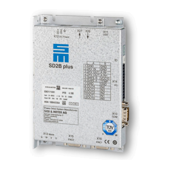
Page 20: Type Plate
Drive Amplifier SD2B plus Type plate Fig. 2: Type plate 0362171DB1xxxx Meaning Explanation Device designation Composed of module type and performance range as letter code IP Code Indicates the level of protection of the device against touching or intrusion of solid objects (1st digit) and water ingress (2nd digit) Device version Indicates the version of the hardware;... -
Page 21: Functional Overview
Drive Amplifier SD2B plus Functional overview The following tables show the properties and the supported drive function of the devices 0362171DA1xxxx and 0362171DB1xxxx. General properties 0362171DA1xxxx 0362171DB1xxxx 740 VA 940 VA Max. output power S1 ✔ ✔ Mains supply: External DC power supply ✔... -
Page 22: Dimensions/Mounting
Drive Amplifier SD2B plus Dimensions/Mounting Fig. 3: Dimensions of SD2B plus in mm (inch) Mounting Instructions Fig. 4: Mounting options ▸ The device is mounted horizontally or vertically to a mounting wall. The mounting surface is used for cooling. Drive Amplifier SD2B plus - 0362171DA1xxxx, 0362171DB1xxxx... -
Page 23: Technical Data
Drive Amplifier SD2B plus ▸ The mounting surface must be able to dissipate a heat output of 25 W at a housing temperature of 60 °C for each device. ▸ With vertical mounting several device can be mounted next to each other without any space in-between. -
Page 24: Connector Pin Assignment
Connector Pin Assignment Connector Pin Assignment Connectors Fig. 5: Connectors of the series 0362171DA1xxxx/ 0362171DB1xxxx Note You can order the appropriate connector kit for SD2B plus at SIEB & MEYER (article No. 32299587). Operation of the Terminal Connectors 6.2.1 Spring-cage Connection The individual conductors are fixed in the terminal by means of spring-cage connection. -
Page 25: Push-In Technology
Connector Pin Assignment Note Solid wires or conductors with ferrules can be put directly into the chamber without the help of a screwdriver. 6.2.2 Push-in technology Terminals using the push-in connection technology (PIT) work on the pressure spring principle: The contact spring presses the cable against the con- ducting copper bar. -
Page 26: X11 - Usb (Parameterization)
Connector Pin Assignment X11 – USB (Parameterization) Communication interface to the connected PC 4-pole female USB connector, type B Name Description 5 V voltage supply for USB Data− Data+ Ground X12 – DC Power Supply 3-pole Combicon connector, suitable for mating connector FKCN 2,5/ 3-ST-5,08 (Phoenix) Mating connector X12 Name... -
Page 27: X13 - Motor Connection
Connector Pin Assignment X13 – motor connection 4-pole Combicon connector, suitable for mating connector FKCN 2,5/ 4-ST-5,08 (Phoenix) Mating connector X13 Name Meaning Motor phase U Motor phase V Motor phase W Protective conductor Specification of terminal connections ▸ Conductor cross-section solid: 1 to 1.5 mm² ▸... -
Page 28: X14 - Inputs/Outputs / Safety Circuit (Sto)
Connector Pin Assignment X14 – Inputs/Outputs / Safety Circuit (STO) 2 ×12-pole Mini-Combicon connector, suitable for mating connector DFMC 1.5/12- ST-3.5 (Phoenix) Mating con- Name Meaning nector X14 Ground 24V IN Logic feed-in 24 V Logic supply 24 V 24V OUT Logic supply 24 V 24V OUT SAFE B / OSSD2... -
Page 29: X15 - Encoder 0
Connector Pin Assignment X14 – Temperature Sensor of the Motor, page 38 X12/X14 – DC Power Supply Unit, page 34 Safety circuit / restart lock (STO), page 56 X15 – Encoder 0 Encoder 0 input, e.g. for length measuring systems 9-pole female submin D connector Name Meaning... -
Page 30: X26/ X27 - Servolink 4
Connector Pin Assignment Hall Sensor 5.3 V, page 42 PULSE IN 5.3 V, page 42 6.11 X26/ X27 – SERVOLINK 4 SERVOLINK 4: optical input (X26) and optical output (X27) The fiber optic connectors for SERVOLINK 4 are located at the top of the device. Connector SIEB &... - Page 31 Connector Pin Assignment Technical data Rated value Storage temperature -40 to 70 °C Operating temperature -20 to 70 °C Tensile stress Between optical fiber cable and connector 19.6 N Optical fiber cable 49 N Min. 25 mm Bending radius When bending the optical fiber cable to install it, note that the recommended bending radius is six to ten times greater than the minimum bending radius.
-
Page 32: Connection Examples
Connection Examples Connection Examples The following sections provide connection examples for the individual connectors of the device. X10 – Bus Connection 7.1.1 COM1 – RS232 Interfaces COM1 – RS232 interface 1 Fig. 6: COM1 – RS232 interface 1 If you connect X10 to a standard RS232 interface of a PC (9-pole male submin D con- nector), the used cable must look like this: Fig. -
Page 33: Can Bus
Connection Examples COM1 - RS232 Interface 2 Additional RS232 connection available: Fig. 8: COM1 - RS232 Interface 2 7.1.2 CAN Bus The CAN interface is designed according to ISO 11898. It is a two-wire connection with differential signals. ISO 11898 specifies a bus cable with two signal lines, CAN_H and CAN_L. -
Page 34: X12/X14 - Dc Power Supply Unit
Connection Examples X12/X14 – DC Power Supply Unit The logic supply at X14 is required under the following conditions: ▸ maintaining the error messages after switch-off is desired ▸ higher output currents of the digital outputs (> 20 mA), see connection ex- ample chapter 7.4.2 “Digital Outputs”, page 35 X13 –... -
Page 35: X14 - In/Out / Sto
Connection Examples X14 – In/Out / STO 7.4.1 Digital Inputs The meanings of the digital inputs can be defined by parameters. 7.4.2 Digital Outputs The output driver can operate as low-side driver or as high-side driver. You can set the desired driver type in the software drivemaster 2. -
Page 36: Analog Input
Connection Examples 7.4.3 Analog Input Voltage interface with input voltage range: ±10 V Can also be connected to potentiometer (500 Ω – 5 kΩ) Drive Amplifier SD2B plus - 0362171DA1xxxx, 0362171DB1xxxx... -
Page 37: Safety Circuit (Sto)
Connection Examples 7.4.4 Safety Circuit (STO) Note See also chapter 10 “Safety circuit / restart lock (STO)”, page 7.4.4.1 Wiring with OSSD OSSD = Output Signal Switching Device 7.4.4.2 Wiring without OSSD OSSD = Output Signal Switching Device Drive Amplifier SD2B plus - 0362171DA1xxxx, 0362171DB1xxxx... -
Page 38: X14 - Temperature Sensor Of The Motor
Connection Examples X14 – Temperature Sensor of the Motor INPUT/OUTPUT: The thermal motor protection is evaluated via these connectors. The drive amplifier supports evaluating the temperature monitoring integrated in the mo- tor. The NTC/PTC behavior of the monitoring is defined in the software (motor parame- ters). -
Page 39: X15, X16 - Incremental Encoders With Ttl Signals
Connection Examples X15, X16 – Incremental Encoders with TTL Signals Fig. 11: Incremental Encoder with TTL Signals Encoder signals: 5V Drive Amplifier SD2B plus - 0362171DA1xxxx, 0362171DB1xxxx... -
Page 40: X15 - Renishaw Biss C Mode (Unidirectional)
Connection Examples X15 – RENISHAW Biss C Mode (Unidirectional) Requirements ▸ 0362171DB with hardware version 4.100 and higher ▸ firmware f11003v04002 and higher, Logic l11001v04011 and higher ▸ drivemaster 2 V1.20 Build 75-17.7.2020 and higher Drive Amplifier SD2B plus - 0362171DA1xxxx, 0362171DB1xxxx... -
Page 41: X16 - Enc1/Emu
Connection Examples X16 – ENC1/EMU 7.8.1 Encoder Emulation Fig. 12: Encoder Emulation The transmission meets the requirements of the standard TIA/EIA-422-B with a voltage differential of at least. ±0.9 V. Drive Amplifier SD2B plus - 0362171DA1xxxx, 0362171DB1xxxx... -
Page 42: Hall Sensor 5.3 V
Connection Examples 7.8.2 Hall Sensor 5.3 V 7.8.3 PULSE IN 5.3 V Drive Amplifier SD2B plus - 0362171DA1xxxx, 0362171DB1xxxx... -
Page 43: X26/X27 - Servolink
Connection Examples X26/X27 – SERVOLINK Drive Amplifier SD2B plus - 0362171DA1xxxx, 0362171DB1xxxx... -
Page 44: Status Display And Error Messages
Status Display and Error Messages Status Display and Error Messages The 7-segment display shows status and error messages. A status message is made up of 1 to 5 digits and displayed as sequence. All messages end with dot behind the last digit. When the first digit is 'E.', there is a permanent error. If the cause of an error can be specified, the display indicates the actual error code fol- lowed by a hyphen and a one-digit sub error code. -
Page 45: List Of Drive Error Messages
Status Display and Error Messages List of Drive Error Messages Note The following messages apply to the entire SD2x drive series. According to the device type or operating mode, certain messages may not appear. Code Error message Error reaction Possible reason ▸... - Page 46 Status Display and Error Messages Code Error message Error reaction Possible reason Communication / bus system error Motor is stopped by parameter-dri- Monitoring of bus communication led to (0x10B) ven ramp and drive is disabled switch-off: ▸ SERVOLINK 4 (267d) (controlled standstill).
- Page 47 Status Display and Error Messages Code Error message Error reaction Possible reason ▸ Ambient temperature too high Motor is stopped by error ramp and Insufficient device cooling ▸ (0x31B) current limitation. SD2M with liquid cooling of the power (795d) components: malfunction of internal ▸...
- Page 48 Status Display and Error Messages Code Error message Error reaction Possible reason ▸ Tracking error monitoring and mo- Motor is stopped by current moni- Wrong parameters ▸ (0x527) tor slowdown toring via short-circuit of the motor Motor connected incorrectly ▸ (1319d) Mechanical problems phases.
- Page 49 Status Display and Error Messages Code Error message Error reaction Possible reason Safety circuit (Safety X10) Drive is immediately disabled, mo- Safety circuit STO is activated (0x52E) tor coasts to standstill without con- when the output stage is active; in- (1326d) trol.
-
Page 50: List Of The Warning Messages
Status Display and Error Messages Code Error message Error reaction Possible reason ▸ FPGA watchdog triggered Device stops in BIOS. FPGA process monitoring has (0x73A) been triggered;. Please contact (1850d) SIEB & MEYER. ▸ No drive parameters loaded Device stops in BIOS. Device is not parameterized (status (0x73B) of delivery). -
Page 51: Messages Of The Quick Stop Functions
Status Display and Error Messages Code Description Reference speed less than minimum motor speed Current greater than warning threshold W26 (warning overload current) Reserved Reserved Reserved Reserved Reserved Messages of the Quick Stop Functions Code Description Digital input "Switch on" waits for positive edge to switch the drive on (This function is only active when the input is set as "Switch on type 2 (with positive edge)".) Software function "Quick stop"... -
Page 52: General Information Regarding The Wiring
General Information Regarding the Wiring General Information Regarding the Wiring Cable Requirements The cables described in this chapter meet the SIEB & MEYER requirements for cables and connectors in order to ensure their proper function. NOTICE Risk of cable damage due to mechanical loads Cables that are exposed to mechanical loads, e.g. - Page 53 General Information Regarding the Wiring Conductor Admissible current I [A] cross-sec- tion A [mm²] E wiring (3 ca- F wiring (3 ca- B2 wiring ble leads) ble leads) – – – – – – – – – – – – –...
-
Page 54: Motor Cable
General Information Regarding the Wiring Standardized cross-sections of round conductors: ISO cross-section [mm²] AWG/MCM Value Equivalent cross-section [mm²] 0.205 – 0.324 0.519 0.75 0.82 – – 13.3 21.2 33.6 53.5 67.4 85.0 – 0000 107.2 250 MCM 300 MCM 350 MCM 500 MCM 600 MCM Note... - Page 55 General Information Regarding the Wiring NOTICE Disturbing ground loops Incorrect connection of protective earth connections in motor cables may cause disturb- ing ground loops and malfunction of the motor. → The described measures prevent disturbing ground loops. → Connect the protective earth conductors additionally led in motor cables directly to the shield line and label them with or PE.
-
Page 56: Safety Circuit / Restart Lock (Sto)
Safety circuit / restart lock (STO) Safety circuit / restart lock (STO) ▸ according to EN ISO 13849-1:2008-12, DIN EN 62061:2005 SIL 3 The restart lock is provided for preventing an unintentional start of a speed-variable dri- ve from the standstill and can, for example, be used in the machine function „Safe stop‟. It comprises a restart lock tested according to EN ISO 13849-1:2008-12 (VDE 0113) and a stop function according to EN 60204-1:2007-6, stop category 0. -
Page 57: Functional Description Of The Restart Lock
Safety circuit / restart lock (STO) Note All mounting locations for safety devices of the control system as well as components mounted outside have to correspond to an IP code IP54, if mounted correctly. 10.1 Functional Description of the Restart Lock The restart lock locks the respective drive of an installation. -
Page 58: Wiring Example
Safety circuit / restart lock (STO) Fig. 15: Safety circuit control DANGER No torque at restart lock activated The motor cannot provide a torque when the restart lock is activated. Thus non-self-locking drives could be released. → Non-self-locking drives as hanging loads must be blocked with a me- chanical brake. -
Page 59: Requirements And Standards
Safety circuit / restart lock (STO) Circuit with OSSD (SIL 3) Fig. 16: Wiring with OSSD The following figure shows a circuit without OSSD safety device, whilst only safety di- rected command devices with forcibly opened contacts in two-channel design are used. SIL 3 (according to EN ISO 13849-1) is achieved. -
Page 60: Restart Lock Procedure
Safety circuit / restart lock (STO) – Performance Level e ▸ according to EN 61508-1:2010 and EN 61800-5-2:2014-06 – PFH = 0 – SFF = 100 % (if there are PFH values, then SFF<100%) – HFT = 0 The safety concept K1 meets the requirements of SIL 3 according to the standards named above. - Page 61 Safety circuit / restart lock (STO) Fig. 18: STO restart lock procedure - Timing and required actions Note Use case A If a STO contact is interrupted during "Switch off", the device status turns to "Switch On Disabled". As soon as the STO contact is closed again, you can restart the device with the next "Switch on".
-
Page 62: Appendix
Specification of Device Firmware Appendix A Specification of Device Firmware For the drive amplifiers of the series SD2B plus the following firmware is available at present. Firmware F11001vxxxxx UF / SVC ✔ SERVO/ VECTOR ✔ Sensorless vector control (SVC), synchronous ✔... -
Page 63: B Manufacturers
Manufacturers B Manufacturers B.1 SIEB & MEYER Accessories In the following you find all accessories for SD2B plus that you can order at SIEB & MEY- Note Consider the information on accessories suitable for your device in the technical manu- B.1.1 Connectors of the Series SD2B plus SIEB &... -
Page 64: B.2 Phoenix Contact
Manufacturers B.2 Phoenix Contact http://www.phoenixcontact.com Order key for Phoenix connectors Note Labeled connectors can be ordered at SIEB & MEYER. Drive Amplifier SD2B plus - 0362171DA1xxxx, 0362171DB1xxxx... -
Page 65: Index
Index Index Special characters 7-segment display Push-in technology 050201 Quick stop messages Accessories Residual current device (RCD) Block DiagramSD2B plus Restart lock Cable Requirements Spring-cage connection Status display STO (Safe Torque Off) Dimensions SD2B plus Technical data SD2B plus Type Plate Error messages USB>RS232/485 Converter Firmware...
Need help?
Do you have a question about the 0362171DA1 Series and is the answer not in the manual?
Questions and answers