Advertisement
Quick Links
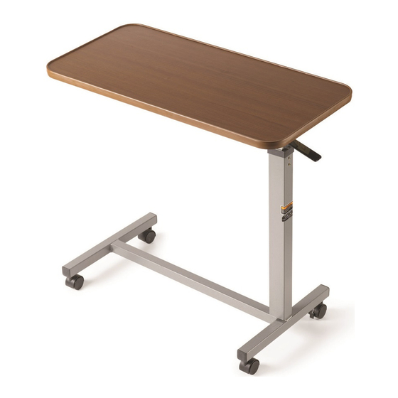
OVERBED TABLE
MODEL NO. 6417
NOTE: Check ALL parts for shipping damage. In case of
shipping damage, DO NOT use. Contact Carrier/Dealer for
further instruction.
SAFETY SUMMARY
WARNING
DO NOT assemble or use this equipment without first
reading and understanding this instruction sheet. If
you are unable to understand the Warnings, Cau-
tions or Instructions, contact a healthcare profes-
sional, dealer or technical personnel before attempt-
ing to install this equipment - otherwise, injury or dam-
age may occur.
After assembly and BEFORE use, ensure that ALL at-
taching hardware is securely tightened.
ASSEMBLING THE OVERBED TABLE
(FIGURE 1)
NOTE: Ensure that the release rod inside the column as-
sembly is visible in the lower (rectangular) portion of the col-
umn assembly as shown in DETAIL “A”. If necessary, shake
the column assembly to allow the release rod to drop into
the column assembly.
NOTE: The release lever MUST be positioned with the curved
side closest to the table top assembly and in between the
release rod and column assembly.
Assembly and Operating Instructions
NOTE: Positioning the overbed table on its side will eleviate
pressure of the base on the bolts.
Bolt Plate
Column Assembly
Release Lever
Bolt
Curved
Side
Release
Release
Column
Lever
Assembly
FIGURE 1 - ASSEMBLING THE OVERBED TABLE
Bolts
Caster
Base Assembly
Shipping Screw/Phillips
Screw
Locknuts
Top Bracket
Table Top
Assembly
Bolt
Rod
Advertisement

Related Manuals for Invacare 6417


Summary of Contents for Invacare 6417
-
Page 1: Safety Summary
OVERBED TABLE MODEL NO. 6417 Assembly and Operating Instructions NOTE: Check ALL parts for shipping damage. In case of shipping damage, DO NOT use. Contact Carrier/Dealer for further instruction. SAFETY SUMMARY NOTE: Positioning the overbed table on its side will eleviate pressure of the base on the bolts. -
Page 2: Limited Warranty
This warranty gives you specific legal rights and you may also have other legal rights which vary from state to state. Invacare warrants its product to be free from defects in materials and workmanship for three (3) years for the original purchaser. If within such warranty period any such product shall be proven to be defective, such product shall be repaired or replaced, at Invacare's option.
Need help?
Do you have a question about the 6417 and is the answer not in the manual?
Questions and answers