Table of Contents
Troubleshooting

Related Manuals for Invacare 5310IVC


Summary of Contents for Invacare 5310IVC
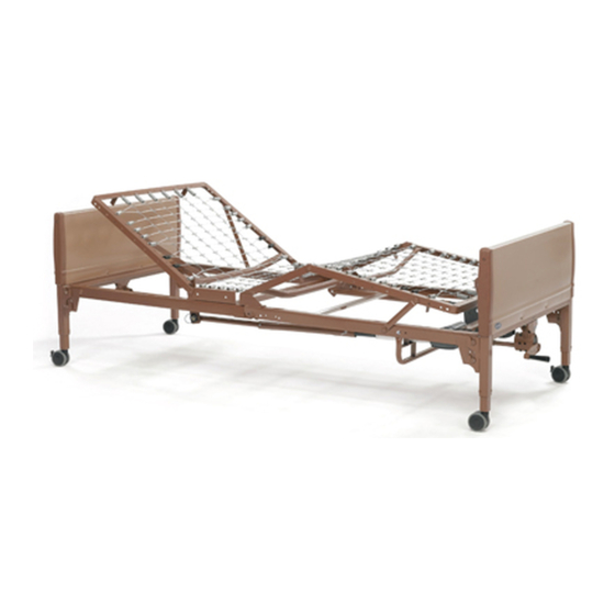
- Page 1 Invacare® Homecare Beds 5411IVC, 5410IVC, 5311IVC, 5310IVC, 5307IVC, 5411LowIVC, 5410LowIVC en User Manual This manual MUST be given to the user of the product. BEFORE using this product, read this manual and save for future reference.
- Page 2 All rights reserved. Republication, duplication or modification in whole or in part is prohibited without prior written permission from Invacare. Trademarks are identified by ™ and ®. All trademarks are owned by or licensed to Invacare Corporation or its subsidiaries unless otherwise noted.
-
Page 3: Table Of Contents
5 Operation ........31 Contents 5.1 Bed Operation and Component Overview . -
Page 4: General
Invacare® Homecare Beds 1.2 Intended Use 1 General The bed is intended to be used as a mattress support 1.1 Symbols system. The bed allows for articulation of the head and foot sections to provide different positions for the patient. It... -
Page 5: Overview
Overview 2.2 Technical Specifications 2 Overview Full Electric 5410IVC, 5411IVC 2.1 Label Locations SHIPPING WEIGHT 176.5 lbs (80.1 kg) WEIGHT CAPACITY OCCUPANT 350 lbs (159 kg) SAFE WORKING LOAD 450 lbs (204 kg) WARNING Close cover when not in use otherwise personal injury may occur. - Page 6 Invacare® Homecare Beds Semi-Electric Single Crank Hi/Lo 5310IVC, 5311IVC Manual Single Crank-Hi/Lo 5307IVC SHIPPING WEIGHT SHIPPING WEIGHT 172 lbs (78.0 kg) 161.5 lbs (73.3 kg) WEIGHT CAPACITY WEIGHT CAPACITY OCCUPANT OCCUPANT 350 lbs (159 kg) 350 lbs (159 kg) SAFE WORKING LOAD...
-
Page 7: Accessories And Accessory Weight
Overview 2.3 Accessories and Accessory Weight Accessories are subject to change. Contact Dealer or Invacare for current list WARNING! DESCRIPTION MODEL NUMBER WEIGHT Risk of Injury or Damage To avoid injury or damage from misuse: MATTRESS Solace Series, 23–31 lbs –... -
Page 8: Safety
Continued use of the product with damaged parts Bed accessories designed by other manufacturers could lead to the product malfunctioning, causing have NOT been tested by Invacare. Use of injury to the user and/or caregiver. NON-Invacare bed accessories may result in injury –... - Page 9 – DO NOT use outdoors. damage. – Connect this product to a properly grounded – Replacement parts MUST match original outlet only. Refer to Operation. Invacare parts. – DO NOT place video equipment such as televisions or computer monitors on product. DANGER! Operating Information...
- Page 10 – The bed is equipped with locking casters. Refer to the Bed Rail Entrapment Risk Notification Before using the bed, test the wheel locks to Guide at www.invacare.com for additional safety ensure casters lock correctly. When transferring information. into or out of the bed, ALWAYS lock the casters.
- Page 11 To avoid patient – Always leave bed in lowest height when entrapment: unattended. – The Invacare mattress MUST fit firmly against the bed frame AND bed side rails to prevent Replacement Parts/Accessories patient entrapment. Follow the manufacturer’s DANGER! instructions.
- Page 12 Otherwise, injury or damage may occur. DANGER! Risk Of Injury Or Adverse Health Consequences Fall hazard exists due to use of Non-Invacare mattresses. Non-Invacare mattresses are potentially incompatible with Invacare beds. – To avoid injury, ensure that only Invacare mattresses are used with Invacare beds at all times.
- Page 13 The of the bed rail and the mattress in which Invacare mattress MUST fit firmly against the individuals may become entangled, adjust the bed frame AND bed side rails to prevent height of the bed rail (if applicable), or provide patient entrapment.
- Page 14 Invacare® Homecare Beds Electrical Grounding Information WARNING! WARNING! Risk Of Death, Injury, Or Damage Risk Of Injury or Damage Shock hazards and risk of fire exist due to use of To avoid injury or damage from improper improper extension cord and use of three prong grounding or using damaged parts: adapters.
- Page 15 Safety Weight Limitations WARNING! Risk Of Product Damage DANGER! The use of accessories, transducers, cords Risk Of Death, Injury, Or Damage and cables other than those specified by the To avoid bed collapse and resulting injury or manufacturer, may result in increased emissions damage: or decreased immunity of this bed –...
-
Page 16: Operating Information
– Keep all product components and accessories incompatible with Invacare beds. a minimum of 12 inches away from hot or – To avoid injury, ensure that only Invacare bed heated surfaces. rails are used with Invacare beds at all times. -
Page 17: Servicing Double-Insulated Products
Safety 3.3 Servicing Double-Insulated Products DANGER! Risk of Death, Injury or Damage Protection to the user against electrical shock hazard is To avoid serious injury or product damage provided by using double insulated construction. Servicing from tripping, entanglement and/or pinched, or a double-insulated product requires extreme care and severed cords: knowledge of the system, and is to be done only by qualified... -
Page 18: Set-Up
– DO NOT plug the power cord into a power the truck driver sign the copy acknowledging the count. source until assembly is complete. 4. If shortage occurs, IMMEDIATELY contact Invacare – DO NOT attempt to operate bed controls prior Customer Service department at (800) 333-6900. - Page 19 Set-up Unpacking the Bed Ends Unpacking Foot and Head Spring Sections 1. Remove any loose packing from the carton A. 2. Bed End carton A includes: • Two Universal Bed Ends B • Four Casters (two locking and two non-locking 1.
-
Page 20: Inspecting
DANGER! Risk Of Injury Or Damage To avoid injury or damage, inspect the following and contact a qualified technician or Invacare if any of the following issues are present: – Pendant covering is cracked or damaged. – Power cord or plug have cuts or damage. -
Page 21: Assembling The Head And Foot Spring Sections
Set-up 4.4 Assembling the Head and Foot Spring 6. Place the head and foot springs approximately 90° from each other. Sections 7. Hook the bottom head spring center mounting latch A to the bottom foot spring center mounting rivet B. 1. -
Page 22: Assembling The Spring Fabric
Invacare® Homecare Beds 4.5 Assembling the Spring Fabric 4.6 Adjusting and Reconnecting the Head Section Pull Tube 1. Lift the head spring C away from the bed frame to give slack to the fabric. 2. Connect the spring fabric A together with the links B provided. -
Page 23: Installing The Casters
Set-up 4.7 Installing the Casters If low bed ends were ordered, proceed to 4.9 Installing Low Bed Ends, page 25, instead of performing this procedure. WARNING! Risk of Injury or Damage To avoid damage or personal injury from instability: – Ensure that the locking casters are installed diagonally from each other and are locked. -
Page 24: Assembling The Universal Bed Ends
4.8 Assembling the Universal Bed Ends 3. Tilt the bed end toward the head spring section and place the rivets B into the corner locks. Invacare recommends that two people perform this 4. Return the universal bed end to its full upright position. procedure. -
Page 25: Installing Low Bed Ends
Low bed ends are designed to be used with Invacare full electric foot spring 5490LOW and head spring 5000IVC. CAUTION! Risk of Damage 1. -
Page 26: Assembling/Installing/Removing Drive Shaft
Invacare® Homecare Beds 4.10 Assembling/Installing/Removing Drive 3. Engage the spring button into the third positioning hole Shaft Reverse this procedure to remove the drive shaft. The drive shaft for Hi/Lo function consists of two sections that are shipped unassembled. The inner... -
Page 27: Inspecting The Bed
No user serviceable parts are All motors, the junction box B, connectors C and wiring inside. Contact dealer or Invacare for are located on the foot spring section. repair/replacement. All connectors will arrive plugged into the junction box. - Page 28 5. Securely attach the cable lock A. Refer to 4.11.1 Installing/Removing Cable Lock, page 29. 6. If damage is found, contact an Invacare Customer Service Representative to report the damaged items and request appropriate replacement parts or products. WARNING!
-
Page 29: Installing/Removing Cable Lock
Set-up 4.11.1 Installing/Removing Cable Lock 4.11.2 Installing the Manual Crank for Hi/Lo Function The following should be performed by a qualified technician only. 1. Pinch the ears A on the input drive shaft cover B to open the cover. Installing 2. -
Page 30: Installing/Removing The Pendant
If bed is not being assembled immediately, retain the cartons and packaging for storage until ready for assembly. Store the Invacare Homecare bed in a dry area. For Canadian Customers who need to disable operation of electric beds: These Models have pendants that can be removed and stored in a secure place. -
Page 31: Operation
– After the thermal protection activation period product is not working properly, contact a is complete, the bed may be prone to sudden qualified technician or Invacare for repair. movement. Use caution when using the product after the protection function time... - Page 32 DANGER! Risk of Death, Injury or Damage Pendant malfunction may cause injury or damage. – Unplug bed from electrical outlet and contact a qualified technician or Invacare for repair if any malfunction is detected. Bed End Head Section Foot Section...
-
Page 33: Operating Full Electric Bed
Operation 5.2 Operating Full Electric Bed 1. To raise the head of the bed G, press the "Head Up" button A. Models 5410IVC and 5411IVC 2. To lower the head of the bed G, press the "Head Down" button B. Before placing the bed into use, test the bed by operating 3. -
Page 34: Operating The Semi-Electric Bed
5.3 Operating the Semi-Electric Bed 1. To raise the head of the bed E, press the "Head Up" button A. Models 5310IVC and 5311IVC 2. To lower the head of the bed E, press the "Head Down" button B. Before placing the bed into use, test the bed by operating 3. -
Page 35: Using The Emergency Crank
Operation 5.3.1 Using the Emergency Crank WARNING! Risk Of Injury Or Damage Due to a power outage or an electronic malfunction, an emergency crank is provided. – DO NOT use the emergency crank to raise the bed. Personal injury or damage to the crank may occur. -
Page 36: Operating The Manual Bed
Do not use for restraint purposes. • Raise and lower the head section with hand crank – Invacare recommends the use of two sets of half length bed rails: one set at the head end • Raise and lower the foot section with hand crank of the bed, and one set at the foot end of the bed where permitted. - Page 37 The bed rails incompatible with Invacare beds. are not intended nor may be used for restraint – To avoid injury, ensure that only Invacare bed purposes. If an individual is capable of injuring rails are used with Invacare beds at all times.
-
Page 38: Maintenance
Drive Shafts use stated in this manual. – Perform all maintenance according to the Invacare reserves the right to ask for any item back that has recommended schedule in this manual. an alleged defect in workmanship. See the Warranty that shipped with the product for specific warranty information. -
Page 39: Cleaning The Bed
– Keep the product away from sparks, flame, and CAUTION! open heat sources. Risk of Damage – Contact your dealer or Invacare for repair. To protect flooring from damage or staining, perform the following: WARNING! – Ensure bed ends are completely drained and Risk Of Injury Or Damage dry before placing on flooring. - Page 40 Invacare® Homecare Beds 1. Stand or prop each bed end in an upright position on Cleaning the Head and Foot Sections its legs. WARNING! 2. Using a mild soap/detergent and soft bristle brush or Risk of Injury or Damage sponge, scrub all exterior surfaces.
-
Page 41: Maintenance And Cleaning Checklist
6.4 Maintenance and Cleaning Checklist 3. Remove bed end caps and plastic cover. 4. Inspect cables and pulleys for wear. Invacare recommends the following maintenance/cleaning 5. Inspect Acme screws for lubrication. Apply a light procedures be conducted initially, between users, or as lithium based grease if necessary. - Page 42 Invacare® Homecare Beds PASS/FAIL PASS: Bed and all components have passed all of the preceding inspection criteria, and the bed is ready for placement into a client’s home. FAIL: Bed, or any component, has failed any of the preceding inspection criteria. Tag the bed or component with a complete description of the failure(s) and have the bed serviced.
-
Page 43: Troubleshooting
Troubleshooting 7 Troubleshooting 7.1 Troubleshooting Mechanical SYMPTOM PROBABLE CAUSE SOLUTION Bed does not stay in place. Casters unlocked. Lock Casters. Bed springs do not move. Pull tube. Check pull tube(s) for binding. Call dealer for repairs. Manual Beds - crank(s) not working. Call dealer. -
Page 44: Troubleshooting Electrical
Invacare® Homecare Beds 7.2 Troubleshooting Electrical SYMPTOM PROBABLE CAUSE SOLUTION Bed spring does not move. End of stroke reached. Operate opposite button. Bed Spring does not stop moving. Pendant. Check for depressed/stuck buttons. If button is stuck, call dealer for repair. - Page 45 Troubleshooting SYMPTOM PROBABLE CAUSE SOLUTION Bed not plugged in. Ensure power cord is plugged into power source. Pendant not functioning. Ensure Pendant is correctly connected to junction box. Ensure Pendant cable not entangled/pinched. Cables. Ensure cables are not entangled/pinched. Call the dealer for repair/replacement of Full Electric Bed: Hi/Lo function does cables and/or motors.
-
Page 46: Warranty
Invacare or a dealer, with a copy of the seller’s invoice required for coverage under this warranty. If within such warranty periods any such product shall be proven to be defective, such product shall be repaired or replaced, at Invacare's option. - Page 47 Notes...
- Page 48 Invacare Corporation www.invacare.com Manufacturing Location Canada 2101 E. Lake Mary Blvd One Invacare Way 570 Matheson Blvd E Unit 8 Sanford, Florida USA Elyria, Ohio USA Mississauga Ontario 32773 44035 L4Z 4G4 Canada (800) 333–6900 800-668-5324 1114836-H-05 2017-02-09 Making Life’s Experiences Possible®...
Need help?
Do you have a question about the 5310IVC and is the answer not in the manual?
Questions and answers