Advertisement
Table of Contents
- 1 Table of Contents
- 2 General Description
- 3 Limitations Of Duct Smoke Detectors
- 4 Contents Of The Duct Smoke Detector Kit
- 5 Exploded View Of Duct Smoke Detector Components
- 6 Installation Sequence
- 7 Wiring Instructions
- 8 Duct Smoke Detector Maintenance & Test Procedures
- 9 Detector Cleaning Procedures
- 10 Board Replacement
- 11 Electrical Specifications
- 12 Specifications
- 13 Warranty
- Download this manual
INSTALLATION AND MAINTENANCE INSTRUCTIONS
DH100ACDCLP Air Duct Smoke Detector
with Extended Air Speed Range
The Innovair DH100ACDCLP model is a photoelectric detector ap-
proved for an extended air speed range of 100 to 4000 feet per
minute (0.5 m/s to 20.3 m/s) and an operational temperature
range of 32°F to 131°F (0°C to 55°C).
Before Installing
Please thoroughly read the System Sensor Guide for Proper Use
of Smoke Detectors in Duct Applications (A05-1004), which
provides detailed information on detector spacing, placement,
zoning, wiring, and special applications. Copies of this manual
are available online at www.systemsensor.com or via System
Sensor's toll free fax-back service, Documents on Demand at
800/736-7672. NFPA Standards 72 and 90A should also be refer-
enced for detailed information.
NOTICE: This manual shall be left with the owner/user of
this equipment.
IMPORTANT: This detector must be tested and maintained reg-
ularly following NFPA 72 requirements. The detector should be
cleaned at least once a year.
Table of Contents
[1] General Description . . . . . . . . . . . . . . . . . . . . . . . . . . . . . 1
[2] Limitations of Duct Smoke Detectors . . . . . . . . . . . . . . . . . 1
[3] Contents of the Duct Smoke Detector Kit . . . . . . . . . . . . . . 1
[4] Exploded View of Duct Smoke Detector Components . . . . . . . 2
[5] Installation Sequence . . . . . . . . . . . . . . . . . . . . . . . . . . . . 2
[7] Detector Cleaning Procedures . . . . . . . . . . . . . . . . . . . . . . 7
[8] Board Replacement . . . . . . . . . . . . . . . . . . . . . . . . . . . . . . 7
[9] Specifications . . . . . . . . . . . . . . . . . . . . . . . . . . . . . . . . . . 8
Warranty . . . . . . . . . . . . . . . . . . . . . . . . . . . . . . . . . . . . . . 8
[1] General Description
An HVAC system supplies conditioned air to virtually every area
of a building. Smoke introduced into this air duct system will be
distributed throughout the entire building. Smoke detectors de-
signed for use in air duct systems are used to sense the presence
of smoke in the duct.
Model DH100ACDCLP Air Duct Smoke Detector utilizes photoelec-
tric technology for the detection of smoke. This detection method,
when combined with an efficient housing design, samples air
passing through the duct and allows detection of a developing
hazardous condition. When sufficient smoke is sensed, an alarm
signal is initiated and appropriate action can be taken to shut off
fans, blowers, change over air handling systems, etc. These ac-
tions can facilitate the management of toxic smoke and fire gases
throughout the areas served by the duct system.
The DH100ACDCLP detector is designed to operate on 24 VDC/
VAC, 120 VAC, or 240 VAC. Alarm and supervisory relay con-
tacts are available for control panel interface (alarm initiation),
HVAC control, and other auxiliary functions. Auxiliary relays
are also provided for fan shut down or signaling of up to 9
other detectors in the loop for multiple fan shut down. These
detectors are not designed for 2-wire applications.
D200-14-00
For testing, the alarm can be enabled by a magnet activated test
switch or by the optional remote test station. The duct smoke
detector latches into alarm state when an alarm occurs. A green
LED flashes to indicate power, a red LED signals local alarm
indication, and optional accessories offer a variety of annuncia-
tion capabilities.
The DH100ACDCLP can be reset by a momentary power inter-
ruption, the reset button on the front cover, the control panel, or
remote reset accessory. The DH100ACDCLP incorporates a cover
tamper feature that provides a trouble signal after 7 minutes if
the cover is removed or improperly installed. Proper installation
of the cover removes the trouble condition.
[2] Limitations Of Duct Smoke Detectors
The National Fire Protection Association has established that
DUCT DETECTORS MUST NOT BE USED AS A SUBSTITUTE FOR
OPEN AREA DETECTOR PROTECTION as a means of providing
life safety. Nor are they a substitute for early warning in a build-
ing's regular fire detection system.
Page
System Sensor supports this position and strongly recom-
mends that the user read NFPA Standards 90A, 72, and 101. The
DH100ACDCLP Air Duct Smoke Detectors are listed per UL 268A.
This device will not operate without electrical power. Fire situa-
tions may cause an interruption of power. The system safeguards
should be discussed with your local fire protection specialist.
This device will not sense smoke unless the ventilation system is
operating and the cover is installed.
For this detector to function properly, it MUST be installed accord-
ing to the instructions in this manual. Furthermore, the detector
MUST be operated within ALL electrical and environmental speci-
fications listed in this manual. Failure to comply with these re-
quirements may prevent the detector from activating when smoke
is present in the air duct.
[3] Contents Of The Duct Smoke Detector Kit
1. Complete housing base and cover assembly
2. Two #10 x 1
1
/
4
3. Two sampling tube filters
4. One test magnet
5. Drilling template
6. Two foam gaskets
7. F our #6-self tapping mounting screws for the metal sampling
tube and optional exhaust tube extension
8. One sampling tube end cap
9. One plastic sampling tube
10. One #8 self-tapping screw for the plastic sampling tube
NOTE: For ducts over 1
ordered to complete the installation. They must be the correct
length for the width of the duct where they will be installed. See
Table 1 on page 3 to determine the inlet tube required for different
duct widths.
1
3825 Ohio Avenue, St. Charles, Illinois 60174
1-800-SENSOR2, FAX: 630-377-6495
www.systemsensor.com
WARNING
˝ sheet metal screws for mounting
1
⁄
feet, longer sampling tubes must be
2
I56-0084-009R
Advertisement
Table of Contents

Related Manuals for System Sensor DH100ACDCLP


Summary of Contents for System Sensor DH100ACDCLP
-
Page 1: Table Of Contents
LED flashes to indicate power, a red LED signals local alarm indication, and optional accessories offer a variety of annuncia- tion capabilities. The DH100ACDCLP can be reset by a momentary power inter- ruption, the reset button on the front cover, the control panel, or remote reset accessory. The DH100ACDCLP incorporates a cover tamper feature that provides a trouble signal after 7 minutes if the cover is removed or improperly installed. Proper installation... -
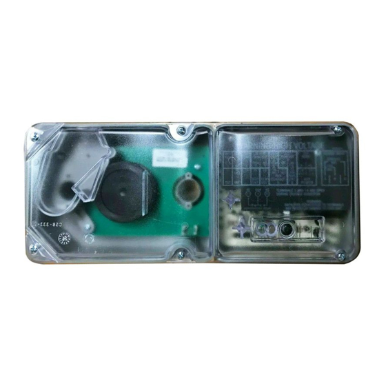
Page 2: Exploded View Of Duct Smoke Detector Components
METAL SAMPLING TUBE DETECTOR BOARD DETECTOR COVER [5] Installation Sequence [5.1] Verify Duct Air Flow Direction And Velocity Model DH100ACDCLP detectors are designed to be used in air han- dling systems having air velocities of 100 to 4000 feet per minute. Be sure to check engineering specifications to ensure that the air velocity in the duct falls within these parameters. If necessary, use a velocity meter (anemometer) to check the air velocity in the duct. [5.2] Drill The Mounting Holes Remove the paper backing from the mounting template supplied. Affix the template to the duct at the desired mounting location. - Page 3 Table 1. Sampling tubes recommended for different duct widths: Outside Duct Width Sampling Tube Recommended* 1 to 2 ft. 2 to 4 ft. 4 to 8 ft. 8 to 12 ft. *Must extend a minimum of the duct width [5.4.1] Installation For Ducts Greater Than 11⁄2 Feet But Less Than 8 Feet Wide 1. I f the tube is longer than the width of the air duct, drill a hole in the duct opposite the hole already cut for the sam- pling tube. Make sure the hole is 1˝ to 2˝ below the inlet hole...
-
Page 4: Wiring Instructions
Wiring Instructions The DH100ACDCLP detectors are designed for easy wiring. The housing provides a terminal strip with clamping plates. Wiring connections are made by stripping about 3/8” of insulation from the end of the wire, sliding the bare end under the plate, and tightening the clamping plate screw. - Page 5 3. T he detector must be reset by system control panel, front cover reset button, or remote accessory. [6.2.2.2] RTS451/RTS451KEY Remote Test Station The RTS451/RTS451KEY Remote Test Station facilitates test of the alarm capability of the duct smoke detector as indicated in the RTS451/RTS451KEY manual. The DH100ACDCLP duct smoke de- tector can be reset by the RTS451/RTS451KEY. If a system control panel is used, the panel itself may also require testing. 15 TO 36VDC To install the RTS451/RTS451KEY, connect the device as shown...
-
Page 6: Wiring Diagrams
Aux. Power + Sup. N. O. Sup. COM Aux. Power – NOTE: Wiring diagram shown is for DH100ACDCLP 4-wire duct smoke detector system equipped without a control panel. NOTE: A trouble condition is indicated when the green LED is not illuminated. -
Page 7: Testing Detector Alarm
SUPERVISORY SIGNAL H0161-01 RESET TEST POWER (–) POWER (+) NOTE: Wiring diagram shown is for DH100ACDCLP 4-wire duct smoke detector system equipped without a control panel. H0160-00 [7.2] Photo Detector Board 1. R emove the screen by gently grasping on each side and pull- ing straight off. 2. L ift the photo chamber in the same fashion. Vacuum the screen and cover. Use clean, compressed air to loosen and... -
Page 8: Electrical Specifications
[9] Model DH100ACDCLP Air Duct Smoke Detector Specifications Operating Temperature: Storage Temperature: Humidity: Air Velocity: Dimensions: Weight: Electrical Specifications Power supply voltage: 20-29 VDC Input capacitance: 270 µF max. Reset voltage: 3.0 VDC min. Reset time (with RTS451): .03 to 0.3 sec. Reset time (by power down): 0.6 sec. max. Power up time: 34 sec. max. Alarm response time: 2 to 17 sec. Sensitivity Test: See detector label Power Supply Voltage CURRENT REQUIREMENTS (USING NO ACCESSORIES) Max.
Need help?
Do you have a question about the DH100ACDCLP and is the answer not in the manual?
Questions and answers