
Related Manuals for Onlogic ML100G-51


Summary of Contents for Onlogic ML100G-51
- Page 1 ML100G-51/52 Manual ML350 Manual Version 1 The not so quick, quick start guide. US Office EU Office Phone: +1 802 861 2300 Phone: +31 85 2733760 Email: info@onlogic.com Email: info@onlogic.eu www.onlogic.com www.onlogic.com...
-
Page 2: Table Of Contents
ML100G-51/52 Industrial Computer ML100G-51/52 Manual About OnLogic . . . . . . . . . . . . . . . . . . . . . . . . . . . . . . . . . . . . . . . . . . . . . . . . . . . . . . . . . . . . . . . . . . . . . . . 3 Contact Information. -
Page 3: About Onlogic
ML100G-51/52 Industrial Computer About OnLogic OnLogic is powering innovation with highly configurable embedded and IoT computers engineered for reliabil- ity. Businesses worldwide depend on our solutions to operate in the toughest environments while tapping into the evolving Industrial Internet of Things. This guide will introduce you to the ML100G-51 and ML100G-52 industrial fanless computers and system speci- fications. For technical questions or support, please reach out via our contact information below. You have a lot of choices when choosing computer hardware. The OnLogic Team wants to thank you for trust- ing our components to meet your application needs. The ML100G-51/52 is the result of input from partners like you. We’ve worked hard to create a system that meets the varied needs of industrial and IoT computing and we’ve manufactured this system under our strict quality assurance and immunity standards to serve you best. If you have any concerns about the quality or performance of this product, please contact us directly or visit our support pages at US: https://www.onlogic.com/company/support/ or EU: https://www.onlogic.com/eu- en/company/support/. -
Page 4: Regulatory Compliance And Safety Information
ML100G-51/52 Industrial Computer Revision History Revision History Date Release of ML100G-51/52 manual 7/31/2019 Regulatory Compliance and Safety Information Regarding equipment: Industrial Fanless PC model(s): xxxxxML100G-51xxxxx and xxxxxML100G-52xxxxx (where x is any alphanumeric character, “-” or blank designating configuration differences) Safe Use and Installation Instructions 1. Do not open or modify the device. The device uses components that comply with FCC and CE regulations. Modification of the device may void these certifications. 2. Install the device securely. Be careful handling the device to prevent injury and do not drop. - Page 5 ML100G-51/52 Industrial Computer WARNING: There is danger of explosion if the CMOS battery is replaced incorrectly. Disposal of battery into fire or a hot oven, or mechanically crushing or cutting of a battery can result in an explosion. Précautions et guide d’installation 1. Ne pas ouvrir ou modifier l’appareil. L’appareil utilise des composants conformes aux réglementations FCC et EC. La modification de l’appareil peut annuler ces certifications. 2. Installez l’appareil en toute sécurité. Soyez prudent lors de la manipulation de l’appareil pour éviter les blessures et ne pas faire tomber. 3. Le montage au mur ou au plafond nécessite l’utilisation d’une plaque de montage ou d’un support. La plaque ou le support doit être en métal et doit avoir une épaisseur minimale de 1 mm. 4. Utilisez des vis à tête plate M3x0,5mm pour fixer la plaque de montage ou les supports aux trous filetés situés au bas ou à l’arrière du châssis. Les vis doivent avoir une longueur minimale de 4 mm. Ajoutez 1 mm de longueur de vis pour chaque mm d’épaisseur supplémentaire de plaque ou de support dépassant 1,5 mm. 5. La température ambiante opérationnelle doit se situer entre 0 °C et 40 °C, ou pour certaines configurations , entre 0 °C et 50 °C avec une humidité relative sans condensation entre 10 et 90%. 6. La plage de températures de stockage doit être de -40 °C à 85 °C. 7. Gardez l’appareil à l’écart des liquides et des matières inflammables. 8. Ne nettoyez pas l’appareil avec des liquides. Le châssis peut être nettoyé avec un chiffon. 9. Laissez au moins 5 cm d’espace autour de tous les côtés de l’appareil pour un refroidissement correct.
- Page 6 ML100G-51/52 Industrial Computer Declaration of Conformity in accordance with the following Directive(s): Electromagnetic Compatibility (2014/30/EU) Low-Voltage (2014/35/EU) RoHS 2 (2011/65/EU) Radio Equipment (2014/53/EU) - Only applicable for configurations with wireless transmitters hereby declare that: Equipment: Industrial Fanless PC model(s): xxxxxML100G-51xxxxx and xxxxxML100G-52xxxxx (where x is any alphanumeric character, “-” or blank designating configuration differences) is in conformity with the applicable requirements of the following documents: • EN 61000-4-5:2014+A1:2017 • EN 55032:2015/AC:2016 Class A • EN 61000-4-6:2014+AC:2015 • EN 55035:2017 • EN 61000-4-8:2010 • EN 61000-3-2:2014 Class D • EN 61000-4-11:2004+A1:2017 • EN 61000-3-3:2013 • EN 62368-1:2014 / A11:2017 • EN 61000-4-2:2009 • EN 301 489-1 V2.2.0 (2017-03) Draft • • EN 301 489-17 V3.2.0 (2017-03) Draft 61000-4-3:2006+A1:2008+A2:2010 •...
-
Page 7: What's In The Box
ML100G-51/52 Industrial Computer 1 - What’s In The Box ML100G-51/52 Built & Tested System If you purchased additional items such as specific mounting brackets, power supplies or antennas, they will be located in the system box or within the outer shipping carton. All drivers and product guides can be found on the corresponding product page at: Any Selected Accessories https://www.onlogic.com/ml100g-51/ https://www.onlogic.com/ml100g-52/ https://www.onlogic.com/eu-en/ml100g-51/... -
Page 8: System Overview
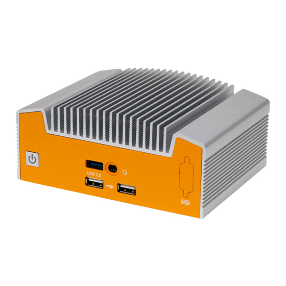
ML100G-51/52 Industrial Computer 2 - System Overview 2.1 - System Diagram 61.5 mm 142.0 mm 111.0 mm USB 3.0 COMBO Audio Jack Optional Serial RS232/422/485 Power Button USB 2.0 USB 3.0 HDMI Optional DIO DisplayPort Gb LAN DC Jack... -
Page 9: System Specifications
ML100G-51/52 Industrial Computer 2.2 - System Specifications ML100G-51 ML100G-52 NUC-8265U NUC-8365UE NUC-8665UE Processor Intel® 8th Gen i5-8265U Intel® 8th Gen i5-8365UE Intel® 8th Gen i7-8665UE Memory Capacity 32 GB 64 GB 64 GB Supported Features vPro, TSX-NI vPro, TSX-NI Memory Type DDR4 SO-DIMM Processor Graphics Intel®... -
Page 10: Mounting Hole Pattern
ML100G-51/52 Industrial Computer 2.3 - Mounting Hole Pattern Ø4.6 mm Ø8 mm Ø4.6 mm 76.2 mm 12.7 mm 156.1 mm 40.5 mm 3.7 mm 10.0 mm 146.1 mm... -
Page 11: Mounting Guide
ML100G-51/52 Industrial Computer 2.4 - Mounting Guide Desk Mounting Step 1: Attach wall mount brackets to chassis Step 2: Mark and prep holes in surface for mounting Step 3: Fasten system to surface VESA Mounting Step 1: Install 4 VESA Screws into your display/surface Step 2: Attach VESA bracket to the chassis Step 3: Hang combined system and bracket to display/surface DIN Rail Mounting Step 1: Attach wall mounting brackets to the chassis Step 2: Attach DIN Rail Clips to the mounting brackets Step 3: Clip system to the DIN Rail... -
Page 12: Motherboard Overview
ML100G-51/52 Industrial Computer 3 - Motherboard Overview... -
Page 13: Jumpers And Headers Guide
ML100G-51/52 Industrial Computer 3.1 - Jumpers and Headers Guide Number Location Function M2M_1 M.2 Key-M Socket 2242/2260 (SATA/PCIe x4) M2E_1 M.2 Key-E Socket 2230 (USB + PCIe x1) USB2_3_4 USB 2.0 Connector COM1 COM Port Header (RS232/422/485) PANEL1 System Panel Header LPC1 LPC Debug Header PWR_JP1 ATX/AT Mode Jumper USB3_3 USB 3.1 Gen 1 Port AUDIO1 Audio Jack... -
Page 14: Configuring Jumpers
ML100G-51/52 Industrial Computer Refer to the following diagrams for configuring jumpers and onboard headers. 3.2 - Configuring Jumpers CLRMOS1 The CLRMOS1 jumper loads the default BIOS settings. Short pins 1-2 for normal operation. Short pins 2-3 to clear the CMOS and reset the system setup configuration to default settings. If you experience challenges powering up, short pins 2-3 to reset the BIOS. Normal Clear CMOS PWR_ JP1 AT = Auto power on. ATX = No auto power on. AT Mode ATX Mode... -
Page 15: Onboard Headers
ML100G-51/52 Industrial Computer 3.3 - Onboard Headers An onboard header is a connection on the motherboard that permits connecting a peripheral component to an external port on the system. USB2_3_4 The USB2_3_4 connector supports two USB ports. 5V_USB 5V_USB Data (Negative) Data (Negative) Data (Positive) Data (Positive) COM1 The motherboard includes an I/O COM Port at 0x3F8 IRQ4 and can support RS232/RS422/RS485. RS232 RS422 RS485 TX (negative) RTX (negative) RXD#... - Page 16 ML100G-51/52 Industrial Computer PANEL1 The system panel header controls the power on and reset buttons, as well as Hard Drive LEDs (HDLED) and Power LEDs (PLED). HDLED (Positive) PLED (Positive) HDLED (Negative) PLED (Negative) PWRBTN RESET None LPC1 The motherboard includes a Low Pin Count (LPC) debug header as a troubleshooting solution. PCICLK FRAME SMBus Clock PCIRST SMBus Data LAD3 LAD2 LAD1 LAD0 None S_PWRDWN 3V_SB SERIRQ...
Need help?
Do you have a question about the ML100G-51 and is the answer not in the manual?
Questions and answers