Table of Contents
Advertisement
Quick Links
Advertisement
Table of Contents

Related Manuals for FAAC 746 E R Z20


Summary of Contents for FAAC 746 E R Z20
- Page 1 746 E R Z16 746 E R Z20 Translation of the original instructions...
- Page 2 Nessuna parte di questo manuale può essere riprodotta, archiviata, distribuita a terzi né altrimenti copiata, in qualsiasi formato e con qualsiasi mezzo, sia esso elettronico, meccanico o tramite fotocopia, senza il preventivo consenso scritto di FAAC S.p.A. Tutti i nomi e i marchi citati sono di proprietà dei rispettivi fabbricanti.
-
Page 3: Eu Declaration Of Conformity
Description: Gearmotor for sliding gates Models: 746 E R Z16, 746 E R Z20 Description: Gearmotors for sliding gates Model: 746 E R Z16, 746 E R Z20... -
Page 4: Table Of Contents
CONTENTS Control devices and accessories ....... 24 EU Declaration of conformity ........3 Radio receiver/decoder board . -
Page 5: Introduction To This Instruction Manual
When drafting the manual, the results of the risk assessment con- WARNING ELECTRIC SHOCK HAZARD - The operation or step described must ducted by FAAC S.p.A. on the entire product life cycle have been taken be carried out following the instructions provided and according to the safety into account in order to implement effective risk reduction measures. -
Page 6: Safety Recommendations
2. SAFETY RECOMMENDATIONS 2.2 TRANSPORT AND STORAGE This product is placed onto the market as “partly completed machin- ery”, therefore it cannot be commissioned until the machine in which Follow the instructions on the package it will be incorporated has been identified and declared to conform to the Machinery Directive 2006/42/EC by the actual Manufacturer. -
Page 7: Unpacking And Handling
2.3 UNPACKING AND HANDLING RISKS PERSONAL PROTECTIVE EQUIPMENT 1. Open the package and remove the contents. - Do not lift the gearmotor by the cover or the electronic board. Grip the body of the gearmotor using the handholds A (1). 2. -
Page 8: Intended Use
- It is prohibited to use and/or install accessories which have not The maximum force required to move the leaf by hand over its entire been specifically approved by FAAC S.p.A. length of travel must be 225 N for residential areas and 260 N for - It is prohibited to use the automation system before performing industrial or commercial areas. -
Page 9: Product Identification
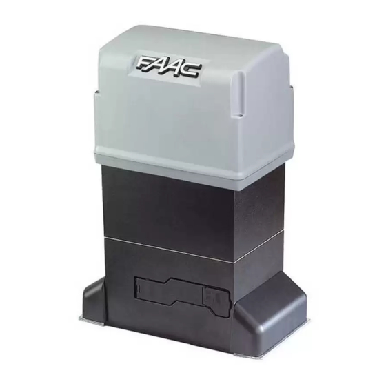
Electromechanical oil-bath gearmotor, supplied with a pinion for the rack. Available in versions: - 746 E R Z16 with pinion Z16 - 746 E R Z20 with pinion Z20 Irreversible system In order to be operated manually, the gearmotor has to be released using the special key. -
Page 10: Component Identification
16 Closing and opening magnetic limit switches (magnets, spacers, mounting hardware and screws) COMPONENTS SUPPLIED SEPARATELY The installation requires the following FAAC components that are supplied separately: Steel rack with spacers (to be screwed or welded on) Nylon rack with mounting hardware - for leaves having a max weight of 400 kg... -
Page 11: Dimensions
3.8 DIMENSIONS Centre distances 6 3.9 MANUAL OPERATION Releasing the gearmotor In order to operate the leaf manually, the gearmotor has to be released using the key provided. Disconnect the power supply from the automation before releasing the gearmotor. During manual operation, gently guide the leaf the whole way. Do not push it and let it slide freely. -
Page 12: Installation Requirements
4. INSTALLATION REQUIREMENTS 4.1 MECHANICAL REQUIREMENTS If the area of installation gives rise to the risk of impact by vehicles, provide an appropriate protective structure to protect the gearmotor. The mechanical structural components must comply with the require- ments of EN 12604. Before installing the automation, the suitability of the mechanical requirements must be established and any work that is necessary in order to meet them carried out. -
Page 13: Example System
4.3 EXAMPLE SYSTEM The example is an illustration only and is just one of the possible ap- plications of the 746 E R (8). Mains power supply 3G 1.5 mm Circuit breaker Junction box Gearmotor 746 E R Photocell TX Photocell RX Key button Flashing light... -
Page 14: Installation Dimensions
4.4 INSTALLATION DIMENSIONS ■ FOUNDATION PLATE Opening to the right Opening to the left 90° 90° 0 … 50 0 … 50 ■ RACK Nylon rack Steel rack 9 746 E R 732099 - Rev.D... -
Page 15: Mechanical Installation
5. MECHANICAL INSTALLATION The installation must comply with standard EN 12453. Mark off the work TOOLS REQUIRED site and prohibit access/transit. The tools required are indicated below ( 6). Installation must be carried out when it is not raining. In case of rain, a suitable shelter for the gearmotor must be provided until the mechanical and Use appropriate tools and equipment in working environments which comply electronic installation has been completed. -
Page 16: Installing The Gearmotor
5.2 INSTALLING THE GEARMOTOR RISKS H = 20 PERSONAL PROTECTIVE EQUIPMENT Carry out the work with the power supply disconnected. 1. Make sure that the concrete of the plinth has set completely, then adjust all the support nuts to the height H indicated (12). 2. -
Page 17: Installing The Rack
5.3 INSTALLING THE RACK RISKS PERSONAL PROTECTIVE EQUIPMENT - DO NOT weld the spacers onto the racks. - DO NOT weld the elements of the rack together. - DO NOT apply grease or other lubricants to the racks. Mounting the rack involves moving the leaf manually several times. -
Page 18: Steel Rack - Screw-On Fastenings
STEEL RACK - SCREW-ON FASTENINGS Rack thickness: 8 mm for leaves weighing up to 400 kg max 12 mm for leaves weighing more than 400 kg The rack installation accessories contain screws for aluminium or steel leaves. -
Page 19: Nylon Rack
NYLON RACK Rack thickness: 20 mm for leaves weighing up to 400 kg max. 1. Close the leaf manually. 2. Rest an element of the rack on the pinion (23). Make sure that it is horizontal using a spirit level. 3. -
Page 20: Adjusting And Checking
5.4 ADJUSTING AND CHECKING 1. In order for it to work correctly, the rack must never rest on the pinion. Turn all the support nuts clockwise by half a turn (25) in order to lower the gearmotor. In this way, a constant distance between pinion and rack is obtained for the entire length of travel (26-A). -
Page 21: Installing The Cover
5.6 INSTALLING THE COVER The cover protects the electronic components and prevents access to moving parts. Never leave the gearmotor unattended without the cover fitted until installation has been completed. Install the cover once the gearmotor has been set-up. With reference to 29, apply the adhesive sign 1 to the cover: risk of fingers and hands being trapped due to the rotation of the pinion and the movement of the rack. -
Page 22: Electronic Installation
Removable terminal board for control devices and accessories (provided in the FC1 FC2 Opening/closing limit switch (depending on the opening direction) hardware/accessories) SAFE Sensitive edges Connector (5-pin) for radio/decoder boards (as indicated in the FAAC catalogue) STOP STOP command J3-J4 Transformer connectors FSW CL Closing photocells... -
Page 23: Connections
7 Board technical data 780D [230 V~] 780D [115 V~] Power supply voltage 220-240 V~ 50/60 Hz 115 V~ 50/60 Hz Max power 10 W 10 W Max. motor power 1000 W 1200 W " Max accessories load 24 V 500 mA 500 mA Ambient operating temperature... -
Page 24: Control Devices And Accessories
CONTROL DEVICES AND ACCESSORIES W.L. Connect the control devices and the accessories to terminal board J1 (36). TX-FSW - Multiple contacts on the same NC input must be connected in series. 24 V 500 mA - Multiple contacts on the same NO input must be connected in parallel. TERMINAL BOARD J1 Connect a push button or another type of NO device. -
Page 25: Radio Receiver/Decoder Board
Install a FAAC 5-pin radio receiver board or a decoder board that is compatible, in terms of frequency and coding technology, with the FAAC radio controls that are used: - a single-channel system only enables the OPEN A radio command - a two-channel system enables the OPEN A and OPEN B/CLOSE radio com- mands (according to the programmed operating logic). -
Page 26: Installing The Cable Glands
7.4 INSTALLING THE CABLE GLANDS 1. Remove the sheath in order to separate the individual wires. 2. With reference to 39, position elements 1 and 2 (with the slot of each inserted in the pin). Arrange the wires on the rubber strip. 3. -
Page 27: Start-Up
8. START-UP RISKS PERSONAL PROTECTIVE EQUIPMENT Install the board cover before switching on the power supply. During operation there is a risk of fingers and hands being trapped between the rack, pinion and cover. Under certain conditions, as a result of prolonged continuous operation, the body of the gearmotor can reach high temperatures. -
Page 28: Installing The Limit Switches
8.1 INSTALLING THE LIMIT SWITCHES Installing the limit switches involves moving the leaf manually several times. Comply with the safety information § Manual operation. The two limit switches are marked with different symbols, square / circle. 1. Assemble the limit switches. Insert the spacer (if necessary) as indi- cated according to the thickness of the rack (41). -
Page 29: Programming The Board
8 Basic programming 8.2 PROGRAMMING THE BOARD BASIC FUNCTION Default Programming must be carried out with the board cover installed. Operating logic: Automatic Semi-automatic step by step Automatic step by step Dead-man Automatic Safety Semi-automatic B Semi-automatic Mixed ( opening / closing) Pause time (carried out in the automatic logics). -
Page 30: Operating Logics
OPEN during closing, causes it to reopen. ADVANCED FUNCTION Default If the closing photocells are triggered during the pause time, they Closing photocells operation (FSW CL) reset the pause time. stop, reverse to open when released reverse, immediate open ■ AUTOMATIC SAFETY Opening photocells operation (FSW OP) This logic only requires the OPEN command to be used. -
Page 31: Adjusting The Anti-Crushing System
8.4 ADJUSTING THE ANTI-CRUSHING SYSTEM The anti-crushing system is realised by a combination of the limitation of static force exerted by the operator in the event of impact and the reverse movement following the detection of the obstacle. We suggest: - start by setting the electronic force to the maximum (function in Basic Programming) - limit the static force to a value lower than 150 N... -
Page 32: Putting Into Service
9. PUTTING INTO SERVICE 9.1 FINAL OPERATIONS RISKS PERSONAL PROTECTIVE EQUIPMENT 1. Make sure that the forces generated by the leaf are within the limits permitted by the current regulations. Use an impact force tester in accordance with standard EN 12453. For non-EU countries, if there are no specific local regulations, the static force must be less than 150 N. -
Page 33: Photocells
10.2 PHOTOCELLS FSW CL Photocells are additional devices that reduce the likelihood of contact with the moving leaf, but they are not safety devices according to standard EN 12978. Use photocells with a NC relay contact. If multiple photocells are used, the contacts must be connected in series. -
Page 34: Sensitive Edges
10.3 SENSITIVE EDGES W.L. Use sensitive edges with a NC relay contact. If multiple sensitive edges are TX-FSW used, the contacts must be connected in series. If the SAFE input is not used, it must be bridged to terminal TX-FSW. 1. -
Page 35: Diagnostics
11. DIAGNOSTICS 10 LEDs on the board 11.1 CONNECTION STATUS bold indicates the condition of the LEDs with the board powered, the gate Move the gate to its halfway position, turn the power on and check the at its halfway position and no connected device active. LEDs on the board ( 10): the status of the LEDs must correspond to those indicated in bold. -
Page 36: Maintenance
Check the rack, ensure it is straight, not worn, that it is the correct distance from FAAC S.p.A. disclaims any liability for damage caused by components that are the pinion along its entire length and correctly fastened to the gate. - Page 37 Check condition, fastening and correct operation. Clean the seats. Access control Check that the gate opens only when an authorised user is recognised. Complete automation system Check that the automation operates correctly, following the set logic, when using the various control devices. Check that the gate moves correctly - smooth, regular and without abnormal noise.
-
Page 38: Instructions For Use
52 13.1 SAFETY RECOMMENDATIONS Systems that use FAAC series 746 E R gearmotors are designed for use with vehicular and/or pedestrian traffic. The user must be in good physical and mental health and be aware of and responsible for the dangers which use of the product can lead to. -
Page 39: Emergency Use
13.2 EMERGENCY USE Releasing the gearmotor Environmental phenomena, even occasional, such as ice, snow and strong wind may hinder correct operation of the automation and affect component integrity and may become a potential source of danger. In emergencies or if there is a fault, turn off the power supply to the automation . -
Page 40: Foundation For Leaves Of Max Weight And Width
1 Foundation for leaves of max weight and width 746 E R 732099 - Rev.D... - Page 41 746 E R 732099 - Rev.D...
- Page 42 746 E R 732099 - Rev.D...
- Page 44 FAAC S.p.A. Soc. Unipersonale Via Calari, 10 - 40069 Zola Predosa BOLOGNA - ITALY Tel. +39 051 61724 - Fax +39 051 09 57 820 www.faac.it - www.faacgroup.com 746 E R 732099 - Rev.D...
Need help?
Do you have a question about the 746 E R Z20 and is the answer not in the manual?
Questions and answers