
Related Manuals for Rion VM-83


Summary of Contents for Rion VM-83
- Page 1 INSTRUCTION MANUAL Vibration Meter VM-83 3-20-41 Higashimotomachi, Kokubunji, Tokyo 185-8533, Japan http://www.rion.co.jp/english/...
- Page 3 Organization of this manual This manual describes the features and operation principles of the vibration meter VM-83. For information regarding the operation of other equipment in the case of incorporating the VM-83 into a measurement system with other equipment, always make sure refer to the documentation of the other equipment.
- Page 4 The product described in this manual is in conformity with the following European standards; Note: CE requirements are met provided that a core fi lter is fi tted to every cable. The measurement result may be infl uenced when the instrument is used in a radio-frequency electromagnetic (RFE) fi eld.
-
Page 5: For Safety
FOR SAFETY In this manual, important safety instructions are specially marked as shown below. To prevent the risk of injury to persons and severe damage to the unit or peripheral equipment, make sure that all instructions are fully understood and observed. Caution D isrega rd i ng i nst r uct ions printed here incurs the risk of... - Page 7 Usage Precautions Operate the unit only as described in this manual. Take care not to drop the unit, and protect it from shocks and vibrations. Do not store or use the unit in locations where the unit may be subject to splashes of water or high levels of dust, air with high salt or sulphur content, or other gases or chemicals, high temperature or humidity (50°C or above, 90%RH or above), or...
-
Page 8: Table Of Contents
Contents FOR SAFETY ................iii Outline ....................1 Controls and Features ..............3 Front panel ................3 Rear panel .................5 Side panel .................7 Display ..................8 Preparations .................. 11 Power supply ................11 Inserting batteries ..............11 AC adapter ................12 Using the prop-up feet ............13 Selecting an accelerometer ............ - Page 9 Serial Interface ................47 Transmission principle ............47 Local mode/Remote mode ............48 Transfer protocol ..............50 Error processing ..............52 Control operation in remote mode ...........53 Command format ..............54 Technical Information ..............69 Noise level and measurement range ........69 Delay of output signal .............73 Rack mounting ................73 Accelerometer installation ............
- Page 10 viii...
-
Page 11: Outline
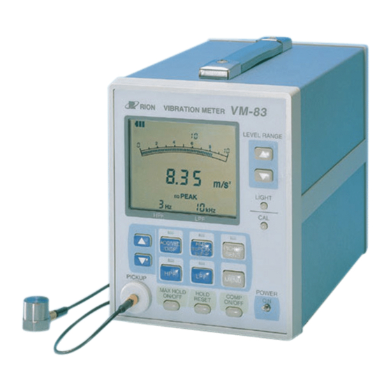
Outline The VM-83 is a vibration meter designed for measurement and evaluation of vibrations, using a piezoelectric accelerometer or a servo accelerometer. It provides four types of input connectors and allows selection of accelera- tion, velocity, and displacement measurement. With the optional servo ac- celerometer, even very low frequency vibrations in the range of 0.1 to 1 Hz... - Page 12 Outline Charge PICKUP amplifier (ACCELEROMETER) PREAMP1 PREAMP2 Regulated power supply 18 V 2 mA Gravity acceleration SERVO canceling circuit Amplifier Amplifier Amplifier Attenuator Amplifier AC OUT Amplifier DC OUT OVER Interface LCD driver EEPROM DC/DC EXT 6 V converter IEC R14 (size C) battery ×...
-
Page 13: Controls And Features
Controls and Features Front panel LEVEL RANGE keys Serve for switching the level range up ( ) or down ( ). Display backlight key (LIGHT key) Serves for turning the display backlight on and off. When the unit is operating on batteries, the display automatically turns itself off after 60 seconds. - Page 14 Controls and Features MENU key Allows changing the menu by selecting a menu number. If this key is pressed in remote mode, the remote mode is canceled and the unit returns to the local mode. Power switch Serves to turn the unit on and off. COMP ON/OFF key Serves to turn the comparator function on and off.
-
Page 15: Rear Panel
Controls and Features Rear panel BATT BOX Battery holder Battery holder button PREAMP 1 AC OUT Preamplifier 1 AC output connector LOCK UNLOCK input connector PREAMP 2 DC OUT Preamplifier 2 DC output connector input connector INPUT SELECT EXT 6V SERVO(LS-10C) PREAMP 2 PREAMP 1... - Page 16 Controls and Features Comparator output terminals The comparator signal is available at these terminals. The maximum applied voltage is 24 V, and the maximum drive current varies as follows depending on the applied voltage. 50 mA (when the applied voltage is 24 V) 25 mA (when the applied voltage is 12 V) 10 mA...
-
Page 17: Side Panel
Controls and Features Side panel... -
Page 18: Display
Controls and Features Display For explanation purposes, the illustration below shows all display elements. In actual use, not all elements will be seen together. COMP indicator This indicator appears when the comparator function is selected. REMOTE indicator This indicator appears when the unit is being controlled remotely over the serial link. - Page 19 Controls and Features Units indicator The unit applicable to the current measurement mode is shown here. When a piezoelectric accelerometer is used, this indicator appears during acceleration measurement. mm/s When a servo accelerometer is used, this indicator appears during acceleration measurement. mm/s This indicator appears during velocity measurement.
- Page 20 Controls and Features UNDER indicator This indicator appears when the input signal has fallen below the mea- surement threshold. Battery capacity indicator Shows the remaining capacity of the batteries. CAL indicator This indicator appears during calibration. Level range indicator Shows which level range has been selected.
-
Page 21: Preparations
Preparations Power supply This unit can be operated either on four IEC R14 (size C) batteries or an AC adapter (option). Inserting batteries Unlock the battery holder by pressing the battery holder button and pull out the battery holder. After replacing the batteries, push the battery holder back into the unit. -
Page 22: Ac Adapter
Preparations Battery life Alkaline batteries LR14 approx. 20 hours Manganese batteries R14P approx. 9 hours * The above values were determined under the following conditions. 20°C 50% RH, accelerometer PV-85, ACC, HPF OFF, LPF OFF, backlight OFF, switch LEDs OFF, communications OFF (MENU 0-0), continuous operation * The actual battery life will differ, depending on the accelerometer, settings, ambient conditions, and battery type or battery manufactures. -
Page 23: Using The Prop-Up Feet
The unit can be tilted by fl ipping out the prop-up feet. Tilt the feet until they snap in place. Important When using the prop-up feet, do not place objects on top of the VM-83 and do not push down on the unit. -
Page 24: Selecting An Accelerometer
Shear type Shear type *1 When mounted with specifi ed screws at specifi ed torque *2 Vertical direction value Servo accelerometer The servo accelerometer model that can be used with the VM-83 is the LS-10C or LS-20C. Model LS-10C LS-20C Voltage sensitivity (V/[m/s 0.300... -
Page 25: Connecting The Accelerometer
Direct connection Use the cable supplied with the accelerometer (VP-51 series) to connect the accelerometer to the accelerometer input connector on the VM-83. Because the input circuit is confi gured as a charge amplifi er, accelerometer cable length has almost no effect on sensitivity. - Page 26 (PV-41, PV-42), use the cable supplied with the accelerometer (VP-51 series) to connect the accelerometer to the PREAMP 2 input connector on the VM-83. Servo accelerometer LS-10C or LS-20C Connecting the servo accelerometer LS-10C or LS-20C Use a cable of the EC-40 series to connect the accelerometer to the SERVO input connector on the VM-83.
-
Page 27: Setting The Input Select Switch
Preparations Setting the INPUT SELECT switch Set the INPUT SELECT switch as required for the type of input that is being used. PREAMP 2 DC OUT INPUT SELECT EXT 6V SERVO(LS-10C) PREAMP 2 PREAMP 1 SERVO PICKUP SERVO SERIAL COMP OUT A COM INPUT SELECT switch PICKUP... -
Page 28: Accelerometer Sensitivity Calibration
Preparations Accelerometer sensitivity calibration Important Different accelerometers have different sensi- tivity. Be sure to perform sensitivity calibration. Sensitivity calibration 1. Set the INPUT SELECT switch as required. 2. Set the power switch to ON. 3. Press the accelerometer sensitivity key (PICKUP SENS key) on the front panel. - Page 29 Preparations 4. Use the setting keys ( , ) to set the display indication to the value indicated as charge sensitivity on the calibration chart of the accel- erometer. When an accelerometer with integrated preamplifi er is used, enter the voltage sensitivity. For example, when the voltage sensitivity is 5.90 mV/(m/s ), use the value 5.90 pC/(m/s For the servo accelerometer LS-10C or LS-20C, enter the value ac-...
-
Page 30: Measurement
Measurement Power-on When the unit is turned on, the same settings as used before the unit was turned off are reestablished ( resume function), and measurement starts. The level range, high-pass fi lter setting, low-pass fi lter setting, and display char- acteristics are memorized for each measurement mode. -
Page 31: Measurement Mode Setting
Measurement Measurement mode setting Select the measurement mode from ACC (acceleration), VEL (velocity), or DISP (displacement). Setting procedure 1. Press the ACC/VEL/DISP key. (The indicator above the key lights up.) 2. Use the setting keys ( , ) to select from ACC DISP. -
Page 32: Display Characteristics Setting
Measurement Display characteristics setting Select the display (detection) characteristics from RMS, PEAK, or P-P. Setting procedure 1. Press the RMS/ PEAK/ P-P key. (The indicator above the key lights up.) 2. Use the setting keys ( , ) to select from RMS PEAK P-P. -
Page 33: High-Pass Fi Lter Setting
Measurement High-pass fi lter setting Setting procedure 1. Press the HPF key. (The indicator above the key lights up.) 2. Use the setting key ( , ) to select the fi lter setting. The available settings are listed below. Piezoelectric accelerometer 1 Hz, 3 Hz, 10 Hz, 20 Hz, 50 Hz, -- (OFF;... -
Page 34: Low-Pass Fi Lter Setting
Measurement Low-pass fi lter setting Setting procedure 1. Press the LPF key. (The indicator above the key lights up.) 2. Use the setting keys ( , ) to select the fi lter setting. The available settings are listed below. Piezoelectric accelerometer 100 Hz, 300 Hz, 1 kHz, 3 kHz, 10 kHz, -- (OFF;... -
Page 35: Level Range Setting
Measurement Level range setting Set the level range as follows. Use the LEVEL RANGE keys ( , ) to select an appropriate level range. The relationship between INPUT SELECT switch, accelerometer sensitiv- ity, measurement mode, and HPF is shown in the table on the next page. - Page 36 Measurement When INPUT SELECT switch is set to PICKUP, PREAMP 1, or PREAMP 2 (*0 HPF: 1 Hz; *1 HPF: 3 Hz; *2 HPF: 10 Hz or above) Measurement Sensitivity Level range mode 1000 3000 10000 0.030 1000 3000 10000 DISP* 1000 3000 10000 0.999...
-
Page 37: Menu Settings
Measurement Menu settings The settings for the serial interface, printer, peak hold function, and compar- ator function are made via menus. 1. Call up the menu screen. Note If one of the keys CAL, COMP ON/OFF, or MAX HOLD ON/OFF is set to ON, the menu screen will not appear. - Page 38 Measurement 2. When the MENU key is pressed, a menu screen as shown below appears. With each push of the MENU key, the menu number cycles through measurement screen. 3. Select the number of the desired menu, and use the setting key ( , ) to change the displayed value.
- Page 39 Measurement Menu 2 Serial interface ID number Choose a setting from 0 to 15. Menu 3 Peak hold function ON/OFF Peak hold function OFF Peak hold function ON Menu 4 Comparator function and comparator level Sets the comparator function and chooses a level between 0 and 98% of the full-scale value, in 2% steps Choose a setting from 0 to 98 in steps of 2.
- Page 40 Measurement Menu 8 Comparator output buzzer This controls buzzer use for the comparator function. When enabled, the buzzer sounds while the comparator output is active. When disabled, there is no buzzer sound also when the comparator output is active. Buzzer disabled Buzzer enabled Note The settings for menu number 0 to 2, and 4 to 8 will...
-
Page 41: Calibration
Calibration When using external equipment to record the AC output signal or DC output signal of the VM-83, perform calibration as follows. In the CAL (calibration) state, the range full-scale signal is output from the AC output connector and DC output connector. - Page 42 Measurement (1) When INPUT SELECT switch on rear panel is set to PICKUP, PRE- AMP 1, or PREAMP 2 AC output connector (AC OUT) : 80 Hz, 2 V* DC output connector (DC OUT) : 2 V (2) When INPUT SELECT switch on rear panel is set to SERVO or SERVO AC output connector (AC OUT) : 1 Hz, 2 V * DC output connector (DC OUT) : 2 V...
-
Page 43: Maximum Value Hold
Measurement Maximum value hold This function serves for holding the maximum measured value. Setting procedure 1. Press the MAX HOLD ON/OFF key to set the function to ON. 2. When the maximum hold function is ON, the indication MAX HOLD appears on the display, and the indicated numeric value is the max- imum value measured up to that point. - Page 44 Measurement 3. When the maximum hold value is higher than the overload threshold, the indication MAX HOLD OVER is shown. 4. The HOLD RESET key can be used to reset the maximum hold value at any time.
- Page 45 Measurement 5. Pressing the MAX HOLD key again turns the maximum hold mode off. The unit returns to normal measurement. Note While the maximum hold function is ON, all controls except the LIGHT key, MAX HOLD ON/OFF key, HOLD RESET key, and power switch are inactive. The maximum hold function applies only to the numeric display.
-
Page 46: Peak Hold
Measurement Peak hold The peak hold function uses 51.2 kHz sampling on the vibration input signal to determine the peak value. Setting procedure 1. Use the MENU key to call up menu 3. 2. Use the setting keys to select the setting 3-1 (peak hold ON). 3. - Page 47 Measurement Note The peak hold function applies only to the numeric display. The bar graph indication continues to func- tion as during normal measurement. While the peak hold function is ON, all controls except the LIGHT key, MENU key, HOLD RESET key, and power switch are inactive.
-
Page 48: Comparator
Comparator Comparator operation The comparator works by constantly monitoring the measured vibration level and comparing it to a preset reference level (comparator level). If the comparator level is exceeded, the comparator output becomes active (open collector circuit, LCD fl ashing, buzzer sounds). To turn the comparator function on and off, use the COMP ON/OFF key. - Page 49 Comparator While comparator function is operating, the COMP indicator is shown. In the bar graph indication, the bar corresponding to the comparator reference level remains constantly on. Comparator level The comparator level is the threshold where the comparator output becomes active.
- Page 50 Comparator Auto reset function The auto reset function is controlled with menu screen 6 (see “Menu Settings” on page 27). When the function is set to ON and the vibration level has fallen again below the comparator level, the comparator output will automatically be reset (turned off) after the auto reset time has elapsed.
- Page 51 Comparator Operation Reset operation When the comparator output was activated, it can be reset in three ways. (1) Auto reset As described above, when auto reset is ON, the comparator output will be turned off automatically after activation when the auto reset time has elapsed.
- Page 52 Comparator Comparator output The comparator output has three elements. (1) Buzzer is heard (long intermittent beeps). This applies only if the buzzer function has been set to ON with menu 8. (2) LCD display fl ashes. Measurement value indicator section fl ashes in 0.5 second intervals. (3) Open collector circuit operates, causing the comparator output ter- minals on the rear panel to close.
-
Page 53: Printer
The following printers are compatible with the VM-83: CP-10, CP-11, DPU-414 Activating printer operation 1. Turn power to the VM-83 and the printer off. 2. Use a generic cable to connect the serial interface connector on the rear panel of the VM-83 to the printer. - Page 54 Printer Stopping printer operation 1. Using the menu screens, select the menu setting 0-0. 2. Disconnect the cable. Note Printer operation is paused during calibration, com- parator operation, sensitivity setting, and while using the menu screens. DIP switch settings for printers CP-11, CP-10 Set the DIP switches for the respective printers as shown below.
- Page 55 When connecting the printer DPU-414, set the DIP switches 1 to 3 for the printer software as follows. For more information on making these settings, please refer to the instruction manual of the DPU-414. Vibration meter VM-83 (9600 bps) SW-1 SW-2...
- Page 56 Printer Printout sample A set of fi ve measurement values for every 2 seconds is printed out every 10 seconds as one line. “ “ is used to indicate an OVER occurrence and “#” an UNDER occurrence.
-
Page 57: Serial Interface
Serial Interface The VM-83 incorporates a serial interface that can be used to set measurement parameters and control measurement using commands sent from a computer. Measurement results can also be sent to the computer. Transmission principle Transfer principle : asynchronous, half-duplex... -
Page 58: Local Mode/Remote Mode
Serial Interface Local mode/ Remote mode Local mode In this mode, the controls on the panel of the VM-83 are used to operate the unit. Immediately after being turned on, the unit is always in local mode. Remote mode In this mode, the VM-83 operates in response to commands sent from a computer. - Page 59 Serial Interface Preparations 1. Turn power to the VM-83 and the computer off. 2. Use a generic cable to connect the serial interface connector on the rear panel of the VM-83 to the computer. Cable : Generic cross-wired serial cable...
-
Page 60: Transfer Protocol
Transfer protocol Sending of commands In order to control the VM-83 from a computer or to retrieve measurement data, certain commands must be sent to the VM-83. The data exchange must be performed according to certain rules, to ensure that both the VM-83 and the computer recognize the commands and data properly. - Page 61 Serial Interface is the ID number. <ACK> Control code 06 (acknowledge) <CR> Control code 0D (carriage return) <LF> Control code 0A (line feed) <EOT> Control code 04 (end of transfer) READY ASCII string (command) ASCII string (command and parameters) (data) ASCII string (data requested by command)
-
Page 62: Error Processing
Serial Interface Error processing In order to ensure correct data exchange between the VM-83 and the com- puter, the rules described above must be observed. If an error occurs, the following steps should be taken. The computer has sent RMT1 <CR><LF>... -
Page 63: Control Operation In Remote Mode
Serial Interface Control operation in remote mode While the VM-83 is in remote mode, only the LIGHT key and MENU key are active. The LIGHT key allows turning the display backlight on and off, and the MENU key in remote mode serves for switching back to local mode. -
Page 64: Command Format
Serial Interface Command format Commands that can be used by the VM-83 consist of 3 characters (3 bytes), usually followed by a parameter which specifi es the action range of the command. There are two types of parameters: Parameters for changing function settings... - Page 65 Serial Interface Command list Command Function See page RMT n1 n2 n3 Select local mode/ remote mode RMT? Get ID number and remote mode status RNG n Set level range UNT n Set measurement mode DET n Set display characteristics SNS n1 n2 n3 n4 Set sensitivity LPF n...
- Page 66 Local mode n1=1 Remote mode n2 n3 = 00 to 15, FF Sets ID number. VM-83 specifi ed by ID number receives the command. FF specifi es all connected VM-83. RMT? Get ID number and remote mode status Output data format p1 p2 p3<EOT><CR><LF>...
- Page 67 Serial Interface When INPUT SELECT is set to PICKUP, PREAMP1, PREAMP2 (*0 = HPF 1 Hz, *1 = HPF 3 Hz, *2 = HPF 10 Hz and higher) Measurement Sensitivity mode 1000 3000 10000 0.030 1000 3000 10000 DISP* 1000 3000 10000 0.999 DISP* 1000 3000 10000...
- Page 68 Serial Interface DET n Set display characteristics PEAK SNS n1 n2 n3 n4 Set sensitivity n1 to n3 Set sensitivity to 030 to 999 n4=0 Set sensitivity to 1/10 of value specifi ed with n1 to n3 n4=1 Set sensitivity to 1/100 of value specifi ed with n1 to n3 n4=2 Set sensitivity to 1/1000 of value specifi ed...
- Page 69 Serial Interface LPF n Set low-pass fi lter setting Command action depends on INPUT SELECT switch setting. Piezoelectric accelerometer PICKUP, PREAMP1, PREAMP2 Servo accelerometer SERVO , SERVO Piezoelectric Servo 10 k n=6* user fi lter user fi lter * This is valid only when the user fi lter is set up by using VM-83PB1 software (option).
- Page 70 Serial Interface HPF n Set high-pass fi lter setting Command action depends on INPUT SELECT switch setting. Piezoelectric accelerometer PICKUP, PREAMP1, PREAMP2 Servo accelerometer SERVO , SERVO Piezoelectric Servo n=6* user fi lter user fi lter * This is valid only when the user fi lter is set up by using VM-83PB1 software (option).
- Page 71 Serial Interface CAL n Set calibration mode. Calibration OFF Calibration ON CAL? Get calibration mode status Output data format p<EOT><CR><LF> Calibration OFF Calibration ON BAT? Get battery capacity status Output corresponds to status of battery capacity indi- cator on display. Output data format p<EOT><CR><LF>...
- Page 72 Serial Interface DOD? Get measurement data Returns a value corresponding to the display indication. Output data format p1 p2 p3 p4 E ± p5, p6 <EOT><CR><LF> p1 to p4 Effective 4 digits of measurement value p5=-6 to +1 p6=O (overload occurred) p6= _ (no overload occurred) (_ is a space) * Explanation of p5...
- Page 73 Serial Interface DOF n Output instantaneous value every 0.1 seconds in non-protocol mode Instantaneous value output OFF Instantaneous value output ON Data will be output every 0.1 seconds. When DOF 0 is received, non-protocol mode output is terminated. For information on output data format, see section on “DOD?”.
- Page 74 Serial Interface MAX n Set maximum hold function to On/Off Maximum hold OFF Maximum hold ON MAX? Get maximum hold function status Output data format p<EOT><CR><LF> Maximum hold OFF Maximum hold ON PEK n Set peak hold function to On/Off Peak hold OFF Peak hold ON PEK?
- Page 75 Serial Interface Reset hold value This command is active during maximum hold, peak hold, and comparator operation. CMP n Set comparator function to On/Off Comparator OFF Comparator ON CMP? Get comparator function status Output data format p<EOT><CR><LF> Comparator OFF Comparator ON...
- Page 76 Serial Interface CMS n1 n2 n3 n4 n5 n6 n7 Make comparator function settings n1 to n2 Comparator level 00 to 98 (steps of 2) Delay time 0 to 9 n4=0 Auto reset OFF n4=1 Auto reset ON n5 to n6 Auto reset time 00 to 90 (steps of 10) n7=0 Buzzer OFF...
- Page 77 Serial Interface STS? Get setting information Output data format p1 p2 p3 p4 p5 p6 p7 p8 p9 p10<EOT><CR><LF> INPUT SELECT 0 to 4 p1=0 PICKUP input p1=1 PREAMP 1 input p1=2 PREAMP 2 input p1=3 SERVO input p1=4 SERVO input Level range 0 to 7 (RNG n) Measurement mode 0 to 2 (UNT n)
- Page 78 Serial Interface Allowable remote mode commands in various operation conditions indicates that command is allowed (valid). × indicates that command is not allowed (invalid). Normal Maximum Peak Command Calibration Comparator Explanation measurement hold hold operation RMT n1n2n3 Cancel remote mode RMT? ×...
-
Page 79: Technical Information
Technical Information Noise level and measurement range (1) Noise level using accelerometer input and sensitivity 5.00 pC/(m/s Measurement Measurement Display Noise level mode range characteristics Acceleration 0.004 m/s Velocity 1 Hz 0.1 mm/s Displacement 1 Hz 0.015 mm Displacement 0.03 10 Hz 0.0003 mm (2) Noise level examples using piezoelectric accelerometer input... - Page 80 Technical Information (3) Measurement range with servo accelerometer LS-10C Acceleration measurement range...
- Page 81 Technical Information Velocity measurement range...
- Page 82 Technical Information Displacement measurement range...
-
Page 83: Delay Of Output Signal
0001 and 2363, t is approx. 600 μs For products with the last four digits of the serial number since 2364, t is approx. 900 μs Rack mounting The VM-83 can be mounted in a rack, using the four screw holes on the bottom of the unit. -
Page 84: Accelerometer Installation
Technical Information Accelerometer installation The accelerometer can be mounted to the measurement object in one of the four general ways outlined below. The accelerometer mounting method greatly affects the contact resonance frequency *. The advantages and disadvantages of various methods are described in this section. Rigid screw mounting This mounting principle assures optimum frequency response characteristics. - Page 85 Technical Information * Contact resonance frequency Contact resonance occurs when the area where the mounted accelerometer contacts the measurement object becomes temporarily deformed, causing it to act like a spring. This spring and the accelerometer mass then form a system that vibrates at a certain resonance frequency. The resonance frequency, which varies considerably depending on the mounting method of the accelerometer, limits the upper range of vibration frequencies that can be measured.
-
Page 86: Display Range
0.1 to 300.0 0.01 to 90.00 The VM-83 directly feeds the raw waveform of the vibration signal to an A/D converter and then performs fi lter processing, rms conversion, and other functions using a DSP. When the number of effective digits for display decreases, display accuracy cannot be maintained. -
Page 87: Aliasing Effect
This principle is subject to the so-called aliasing effect. An anti-aliasing fi lter (analog low-pass fi lter) serves to counter this effect. In the VM-83, a 5th-order fi lter is used for this purpose. Note that the fi lter has the effect shown below. -
Page 88: Filter Characteristics
Technical Information Filter characteristics Piezoelectric accelerometer High-pass fi lter Low-pass fi lter The above specifi cations are a representative example for AC output. - Page 89 Technical Information Servo accelerometer LS-10C High-pass fi lter Low-pass fi lter The above specifi cations are a representative example for AC output.
-
Page 90: Vm-83Pb1 Software
2000, XP and Microsoft Windows NT4.0 which allows controlling settings and measurement operation of the VM-83 from the computer, via the serial port. Measurement data downloaded from the VM-83 can be stored in text fi le format, allowing further processing for example using a spreadsheet program. -
Page 91: Specifi Cations
Specifi cations Applicable standards CE marking Input Section (1) PICKUP input For piezoelectric accelerometer (microdot connector) Maximum input charge 30000 pC (2) PREAMP 1 input For piezoelectric accelerometer via preamplifi er VP- 26A (7-pin female connector PRC-03) (3) PREAMP 2 input For piezoelectric accelerometer with integrated pre- amplifi er 18 V, 2 mA drive (microdot connector) - Page 92 Specifi cations - Accelerometer sensitivity 1.00 to 9.99 pC/(m/s Acceleration 0.3, 1, 3, 10, 30, 100, 300, 1000 m/s Velocity 3, 10, 30, 100, 300, 1000 mm/s Displacement 1, 3, 10, 30, 100, 300, 1000 mm (HPF 1 Hz) Displacement 0.3, 1, 3, 10, 30, 100, 300, 1000 mm (HPF 3 Hz) Displacement 0.03, 0.1, 0.3, 1, 3, 10, 30, 100 mm (HPF 10 Hz or higher) - Accelerometer sensitivity 10.0 to 99.9 pC/(m/s...
- Page 93 Specifi cations Filters Piezoelectric accelerometer OFF, 1, 3, 10, 20, 50 Hz (-10% point), selectable OFF, 100, 300, 1 k, 3 k, 10 kHz (-10% point), selectable Servo accelerometer 0.1, 0.3, 1 Hz, selectable 50, 100 Hz, selectable Display (detection) characteristics Effective value (RMS) True rms Equivalent peak value (...
- Page 94 Specifi cations Display functions (1) Bar graph linear scale, 100 ms sampled value 0 to 3.16 0 to 10 (2) Measurement value 4-digit numeric display; arithmetic average of 20 in- stantaneous values taken at 100 ms intervals, updated every 2 seconds (3) Measurement mode, display characteristics, fi lter (4) Battery status 3-segment indication...
- Page 95 Specifi cations Outputs (1) AC output Range full-scale 2 V, output impedance 600 Ω, BNC connector Load impedance 10 kΩ or higher Output voltage accuracy Piezoelectric (unit electrical characteristics, 80 Hz) Acceleration range full-scale ±2% Velocity range full-scale ±3% Displacement range full-scale ±5% Servo accelerometer (overall accuracy with LS-10C 1 Hz)
- Page 96 Specifi cations Noise level (1) Noise level with accelerometer input, sensitivity 5.00 pC/(m/s Measurement Measurement Display Noise level mode range characteristics Acceleration 0.004 m/s Velocity 1 Hz 0.1 mm/s Displacement 1 Hz 0.015 mm Displacement 0.03 10 Hz 0.0003 mm (2) Noise level examples using piezoelectric accelerometer input Accelerometer Measurement...
- Page 97 Specifi cations (3) Measurement range with servo accelerometer LS-10C Acceleration measurement range...
- Page 98 Specifi cations Velocity measurement range 1000 1.59 mm /s 0.159 mm /s 0.05 0.02 0.01 0.005 1.59 Hz 0.002 0.001 0.02 0.05 0.01 1000 Frequency (Hz)
- Page 99 Specifi cations Displacement measurement range...
- Page 100 Specifi cations Interface Serial interface For data output and remote control 9-pin D-sub male connector Half-duplex communication with protocol Transfer rate 9600 bps, 19200 bps Printer output For data output to printer (CP-10, CP-11, DPU-414) Ambient conditions for operation −10°C to +50°C, 20% to 90% RH (no condensation) Power requirements IEC R14 (size C) batteries (×4) or optional AC adapter NC-98 series...
- Page 101 Specifi cations Supplied Accessories Carrying case IEC R14 (size C) batteries Instruction manual Inspection Certifi cate Optional Accessories AC adapter NC-98 series (100 V to 240 V) Piezoelectric accelerometer Vibration meter preamplifi er VP-26A Extension cable EC-02S series Servo accelerometer LS-10C Servo accelerometer cable EC-40 series...
- Page 102 Specifi cations Unit: mm Dimensional drawings...
-
Page 103: Index
Index CMS? ------------------------------ 55, 66 CMS n1 n2 n3 n4 n5 n6 n7 ----- 55, 66 AC adapter -------------------------- 5, 12 Comparator function ------------- 55, 83 Acceleration measurement range Comparator operation ----------------- 38 -------------------------------------- 70, 87 Comparator output -------------------- 42 Accelerometer -------------------- 14, 74 Comparator output terminals -- 5, 6, 42 Accelerometer input connector ------- 4... - Page 104 Index Equivalent peak ------------------- 22, 83 MAX? ------------------------------ 55, 64 Equivalent peak-to-peak --------- 22, 83 MAX HOLD ON/OFF key ----------- 4 Error processing ----------------------- 52 maximum hold function -------------- 55 External power supply connector 5, 12 Maximum value hold ------------ 33, 83 maximum value hold function -------- 4 MAX n ----------------------------- 55, 64 Feet --------------------------------------- 7...
- Page 105 Index preamplifier ---------------------------- 15 Preamplifier 1 input connector ------- 6 UNDER indicator --------------------- 10 Preamplifier 2 input connector ------- 6 Units indicator -------------------------- 9 Printer ----------------------------------- 43 UNT n ------------------------------ 55, 57 Printer output -------------------------- 90 Printout sample ------------------------ 46 Velocity measurement range ---- 71, 88 prop-up feet ------------------------- 7, 13 Vibration frequency range ------------ 82...
- Page 106 This product is environment-friendly. It does not include toxic chemicals on our policy. No. 63760 18-07...
Need help?
Do you have a question about the VM-83 and is the answer not in the manual?
Questions and answers