
Related Manuals for Rion VA-11


Summary of Contents for Rion VA-11
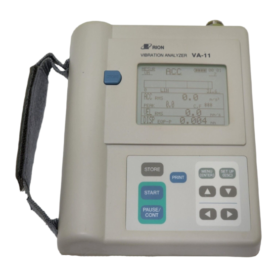
- Page 1 INSTRUCTION MANUAL VIBRATION ANALYZER VA-11 3-20-41 Higashimotomachi, Kokubunji, Tokyo 185-8533, Japan...
-
Page 3: Organization Of This Manual
Organization of this manual This manual describes the features and operation principles of the Vibration Analyzer VA-11. This manual contains the following sections. Outline Gives basic information on the unit. Controls and Features Briefly identifies and explains all parts of the unit. - Page 4 Compact Flash Card Describes how to use the separately available compact flash cards for data storage. Default Settings Lists the default settings of the unit (the condition in which it is shipped from the factory). Specifications Lists the technical specifications of the unit. The product described in this manual is in conformity with the following European standards;...
-
Page 5: For Safety
FOR SAFETY In this manual, important safety instructions are specially marked as shown below. To prevent the risk of death or injury to persons and severe damage to the unit or peripheral equipment, make sure that all instructions are fully understood and observed. -
Page 6: Warning
WARNING When making measurements on exposed rotating parts or power train parts of machinery, proceed with utmost care to ensure that the accelerometer or accelerometer cable do not get caught in the machine. When making measurements on exposed rotating parts or power train parts of machinery, do not use the shoulder belt or carrying strap. -
Page 7: Precautions
PRECAUTIONS Operate the unit only as described in this manual. Do not touch any parts of the unit other than necessary for operation. Do not drop the unit. Protect it from shocks and vibration. The permissible ambient temperature range for operation of the unit is 0 to +40ºC. -
Page 8: Table Of Contents
Contents Organization of this manual ..............i FOR SAFETY ................... iii WARNING ................... iv PRECAUTIONS ................v Outline ....................1 Controls and Features ................. 3 Front Panel ..................3 Side Panel ..................6 Top Panel ..................7 Bottom Panel ................8 Preparations .................. - Page 9 Measurement ..................54 Use As a Vibration Meter ............54 Use As a Spectrum Analyzer ............56 Spectrum List Display ..............57 Time Waveform Display ............. 58 Cursor Control ................60 Recall Mode ..................61 Recalling Transient Store Data ........... 62 Recalling Manual Store Data ............
- Page 10 viii...
-
Page 11: Outline
Outline The VA-11 is a portable analyzer designed for examining machinery vibrations and performing diagnostic routines on various kinds of equipment. It has a basic but highly useful array of functions. Except for envelope processing, all processing functions are carried out in the digital domain. The built-in compact flash card slot allows easy storage and export of data to a computer. - Page 12 Outline Block diagram of vibration analyzer VA-11...
-
Page 13: Controls And Features
Controls and Features Front Panel Display Measured waveforms, menus, and other data are shown here. PRINT key Pressing this key causes the currently displayed measurement screen or data stored in memory to be printed out. Do not press the PRINT key when a computer is connected to the I/O connector. - Page 14 Controls and Features MENU (ENTER) key Allows changing the measurement parameters using the menus. SETUP (ESC) key Allows changing the measurement parameters directly on the measurement screen. keys Used to select setting items when changing the measurement parameters. keys Used for cursor movement and for changing measurement parameters. START key Used to start the measurement.
- Page 15 Controls and Features Carrying strap For carrying, hold the unit as shown below. WARNING When making measurements on exposed rotating parts or power train parts of machinery, proceed with utmost care to ensure that the pickup or pickup cable do not get caught in the machine.
-
Page 16: Side Panel
Controls and Features Side Panel POWER switch Turns the unit OFF and ON. EXT DC IN jack The optional AC adapter NC-94A can be connected here for operation on AC power. Important Use only the optional AC adapter NC-94A to prevent the possibility of damage. -
Page 17: Top Panel
Controls and Features Top Panel Accelerometer connector The supplied accelerometer PV-55 is connected here. (Other compatible accelerometers: PV-57, VP-26C) LIGHT switch Pressing this switch turns on the display backlight, and pressing the switch again turns it off. The backlight also turns itself off automatically after three minutes of inactivity. -
Page 18: Bottom Panel
Controls and Features Bottom Panel Battery compartment Four IEC R14 (size C) batteries and one lithium battery are inserted here. -
Page 19: Preparations
Preparations Power Supply Inserting the batteries 1. Set the POWER switch to OFF. 2. Open the cover of the battery compartment. The illustration below shows the unit with the cover removed. Pay attention to correct polarity. - Page 20 Preparations 3. Insert four IEC R14 (size C) batteries with correct polarity, as shown in the illustration below. 4. Insert the lithium battery with correct polarity. 5. Replace the battery compartment cover. Important Take care not to mix up [+] and [-] polarity when inserting the batteries.
- Page 21 Preparations When to replace the batteries The battery indicator at the top right of the display gives an indication of battery status. The number of lit segments decreases as the batteries are depleted. When only one segment is shown, you should replace the batteries. When using alkaline batteries, the approximate battery life is 22 hours of continuous operation.
- Page 22 Set the POWER switch to OFF and replace the batteries as described on pages 9 to 10. When the POWER switch is turned on, the Rion logo will normally be shown on the display for five seconds, and then the measurement screen appears. If the battery capacity is low, the logo screen stays on the display.
- Page 23 Preparations Important Use only the supplied AC adapter NC-94A to prevent the possibility of damage. Important Do not coil or twist the power cord of the AC adapter. Do not cover the AC adapter or the power cord with cloth, paper or any other object, to prevent the possibility of heat buildup.
-
Page 24: Connecting The Accelerometer Pv-55
Preparations Connecting the Accelerometer PV-55 Connect the acceleration accelerometer PV-55 as shown below. After inserting the plug into the connector, rotate the connector ring clockwise to firmly lock the plug. The start switch on the accelerometer operates in the same way as the START key on the unit. -
Page 25: Trigger Input
Preparations Trigger Input The trigger function (see page 45) can be used to control the measurement. -
Page 26: Printer And Computer Connections
To connect the printer DPU-414, CP-11 or CP-10 (option) to the I/O connector on the VA-11, use a commercially available RS-232-C interface cable (straight cable). To connect a computer to the I/O connector on the VA-11, use a commercially available RS-232-C interface cable (cross-wired or null modem... - Page 27 Preparations DIP switch setting on printer DPU-414 Set the DIP switches of the printer as shown below. For details, please refer to the instruction manual of the DPU-414.
- Page 28 The ON position means 4800 bps and the OFF position 9600 bps. For the VA-11, use the 9600 bps setting. Switches 7 and 8 of DIP switch bank 2 of printer CP-11 are set at the factory and should not be changed.
-
Page 29: Setting The Date And Time
Preparations Setting the Date and Time Before using the unit, you must set the date and time for the built-in calendar/ clock. (The calendar/clock is not set at the factory before shipping.) 1. Set the POWER switch to ON. 2. After the measurement screen has appeared, press the MENU (ENTER) key once to call up the MAIN MENU screen. -
Page 30: Using The Shoulder Belt
The years from 2000 to 2009 are indicated as a single digit. However, when data stored internally in the unit are written to a memory card, the year information will be in four digits, as shown below. VA-11 data Data on memory card 0 to 89 2000 to 2089... -
Page 31: Display Explanation
Display Explanation Display Layout Information appearing on the display screen can be divided into two main categories: • Current measurement data (MESUR) or recalled measurement data (RECLL) • Measurement parameter settings (MENU) Details of these are explained below. Current measurement data (MESUR) or recalled measurement data (RECLL) Measurement parameters (MENU) -
Page 32: Measurement Screens
Display Explanation Measurement Screens The actual display may differ from the screen samples shown here. Vibration meter display Items which are underlined on screen can be changed on the measurement screen by pressing the SETUP (ESC) key. Measurement data type ACC: Acceleration VEL: Velocity DISP: Displacement... - Page 33 Display Explanation Input range with ( ) Full-scale value when accelerometer with different sensitivity than PV-55 is used (normally not shown). Input range Determined by combination of vibration quantity and unit, as shown below. Bar graph scale LIN: Linear scale LOG: Log scale rms value Root mean square of...
- Page 34 Display Explanation Spectrum display Items which are underlined on screen can be changed on the measurement screen by pressing the SETUP (ESC) key. Measurement data type ACC: Acceleration VEL: Velocity DISP: Displacement ACCe: Envelope curve Measurement state MESUR: Measurement RECLL: Recall Analysis mode VM: Vibration meter SPEC: Spectrum...
- Page 35 Display Explanation Total averaging count 1 to 1023 Shows the selected number for exponential averaging, linear averaging, and maximum value. Input range Frequency span 100, 200, 500, 1 k, 2 k, 5 k, 10 k, 20 kHz Frequency zoom setting Zoom ratio ×1, ×2, ×4, ×8 Y axis zoom Y dB: ×1 = 80 dB display...
- Page 36 Display Explanation Cursor Y axis unit Can be switched between dB and LINEAR with SPECTRUM menu. Set separately from Y axis scale. Cursor X axis unit Can be switched between Hz, KCPM, and ORDER with SPECTRUM menu. Overall value Full power spectrum value excluding DC component. Cursor position frequency display shows "AP".
- Page 37 Display Explanation Memory address 1 to 500 Averaging type INST: Instantaneous value LIN: Linear averaging EXP: Exponential averaging MAX: Maximum value Total averaging count 1 to 1023 Input range Frequency span 100, 200, 500, 1 k, 2 k, 5 k, 10 k, 20 kHz Frequency zoom setting Zoom ratio ×1, ×2, ×4, ×8 Cursor Y axis unit...
- Page 38 Display Explanation Time waveform display Items which are underlined on screen can be changed on the measurement screen by pressing the SETUP (ESC) key. Measurement data type ACC: Acceleration VEL: Velocity DISP: Displacement ACCe: Envelope curve Measurement state MESUR: Measurement RECLL: Recall Analysis mode VM: Vibration meter...
- Page 39 Display Explanation Input range Frequency span 100, 200, 500, 1 k, 2 k, 5 k, 10 k, 20 kHz Frequency zoom setting Zoom ratio ×1, ×2, ×4, ×8 X axis zoom (can be changed for frequency zoom factor of 2 or above) ×1, ×2, ×4, ×8 (up to frequency zoom ratio) Y axis zoom ×1, ×2, ×4, ×8, ×16, ..., ×1024...
- Page 40 Display Explanation Operation status indicators Battery indicator Shows the remaining capacity of the dry-cell batteries in the unit (see page 11). Trigger indicator (only in analyzer mode) In free-run mode, nothing is displayed here. In other modes, "TRG" is shown. When the unit is waiting for trigger activation, the reverse indication [WAIT] flashes in 0.5 second intervals.
- Page 41 Display Explanation Overload indicator The indication "OVER" appears if an acceleration signal has exceeded the input range by 0.5 dB or more.
-
Page 42: Menu Screens
Display Explanation Menu Screens Pressing the MENU (ENTER) key brings up the MAIN MENU screen. This screen allows the user to select measurement parameters to be changed. Pressing the MENU (ENTER) key again brings up the selected menu. MAIN MENU items UNIT: Measurement units TRIGGER:... - Page 43 Display Explanation UNIT menu screen UNIT menu screen items ACC: Acceleration unit Unit: RMS VEL: Velocity unit mm/s inch/s Unit: RMS DISP: Displacement unit mils Unit: EQp-p 1. Use keys to select menu item. 2. Use keys to change settings. Not available during recall.
- Page 44 Display Explanation TRIGGER menu screen TRIGGER menu screen items MODE: Trigger operation mode FREE: Free-run trigger REPEAT: Repeat trigger SINGLE: Single trigger SOURCE: Trigger source LEVEL: Level trigger EXTERNAL: External trigger TRIG POINT: Trigger point (settable in 16 steps) Zoom ×1 0 to 240 ×2...
- Page 45 Display Explanation MASS MEMORY menu screen MASS MEMORY menu screen items TYPE: Memory store type MANUAL: Manual store TRANSIENT: Transient store TIMER: Timer operation Timer operates OFF: Timer is off HOUR: 0 to 23 in 1-hour steps (timer start time) MINUTE: 0 to 59 in 1-minute steps (timer start time) DURATION: 1 to 60 in 1-minute steps (store interval)
- Page 46 Display Explanation PCMCIA CARD menu screen PCMCIA CARD menu screen items DIR: Select directory display keys to change "OFF" to "EXEC". EXEC: Press MENU (ENTER) key to execute. One screen shows up to 10 blocks with the respective store date. When there are more blocks, the keys can be used to scroll the display.
- Page 47 Display Explanation SAVE MOMERY: Select save EXEC: Press MENU (ENTER) key to execute. DELETE: Select delete EXEC: Press MENU (ENTER) key to execute. FORMAT: Select format EXEC: Press MENU (ENTER) key to execute. Formats a card to create directory structure and key file. SAVE DISPLAY: Controls the direct card write function that allows writing data directly to the card.
- Page 48 Display Explanation Error message Meaning "NO CARD": No card is inserted. "BAD CARD": Type of inserted card does not match the unit. "READ/WRITE ERROR": Read or write cannot be performed. "NO SPACE": There is not enough empty space on the card. INPUT menu screen INPUT menu screen items SENSITIVITY: Enter sensitivity of accelerometer in use...
- Page 49 (When using a different accelerometer) The sensitivity of the supplied Vibration accelerometer PV-55 is 5.1 mV/m/s When using a different accelerometer, change the setting at the VA-11 so that it matches the sensitivity of the accelerometer. (The sensitivity is indicated in the calibration chart that comes with the accelerometer.)
- Page 50 Display Explanation SPECTRUM menu screen SPECTRUM menu screen items WINDOW: Time window type (cannot be set while recalling) RECTANGLE: Rectangular window HANNING: Hanning type window FLATTOP: Flat-top type window X-CURSOR: Cursor X axis unit: Hz, KCPM, ORDER When ORDER is selected, the current cursor position becomes the fundamental frequency.
- Page 51 Display Explanation SETUP MEMORY menu screen SETUP MEMORY menu screen items ADDR: Address and store date display Address: 0 to 10 Store date: Eight asterisks are shown if no setting data are present. SAVE: Save setting data in specified address. keys to change "OFF"...
- Page 52 Display Explanation OTHERS menu screen OTHERS menu screen items PRINTER: Printer output type SINGLE: Only the displayed screen is printed. SUCCESSIVE: Data stored in the memory are printed successively. (Possible only for manual store data) To execute printing, return to the measurement screen and press the PRINT key.
- Page 53 Display Explanation CALENDAR menu screen CALENDAR menu screen items DISPLAY: Select item to be shown at top right of measurement screen DATE: Show date TIME: Show time OFF: Show nothing HOUR: Set hours (0 to 23) MINUTE: Set minutes (0 to 59) YEAR: Set year (0 to 99) MONTH:...
-
Page 54: Menu Operation On Measurement Screen
Display Explanation Menu Operation on Measurement Screen Measurement parameters can also be changed while the measurement screen is displayed. To do this, proceed as follows. 1. Press the SETUP (ESC) key to display the reverse cursor. 2. Use the keys to move the reverse cursor. Items that can be changed are shown with an underline. -
Page 55: Trigger Functions
Trigger Functions The trigger functions of the VA-11 are available only in analyzer mode. By pressing the START key on the pickup or the main unit, the trigger standby condition is activated. Time waveform sampling as well as FFT processing and averaging then will start automatically when the trigger condition is met. - Page 56 Trigger Functions Input level: Set the SOURCE item on the TRIGGER menu to LEVEL. Trigger is activated when the time waveform crosses the set level. The level can be set in steps of 1/8 of the full-scale unilateral amplitude, and the slope can also be selected, to determine whether triggering occurs when the waveform crosses the level from above or below.
- Page 57 Trigger Functions Single: When trigger occurs, processing is carried out once. Subsequent trigger occurrences are ignored until START key is pressed again. Pre-trigger and post-trigger functions Pre-trigger: Processing starts from a specified number of data before trigger occurrence. Post-trigger: Processing starts from a specified number of data after trigger occurrence.
-
Page 58: Processing Principles
Processing Principles Processing operation Processing starts when the START key is pressed or when one of the measurement parameters listed below is changed. Measurement parameters that cause processing start: • Measurement state • Analysis mode • Measurement data • Averaging type •... - Page 59 Processing Principles Repeat Instantaneous value, exponential averaging Free-run Single Repeat...
-
Page 60: Mass Memory
The data of 2 kHz and below are available for real time analysis. Mass Memory The VA-11 incorporates a memory for storing measurement results and measurement parameters for the vibration meter mode and analyzer mode. The number of memory slots is 500, identified by a memory address. - Page 61 Processing Principles Data store There are two types of functions for data storing: manual store and transient store. These are selected by setting the TYPE item in the MEMORY menu to MANUAL or TRANSIENT. When the store type was changed, all previous data will be cleared at the point when the first store operation is carried out.
- Page 62 Processing Principles • If the POWER switch is set to OFF during transient store, store continues until address 500, and the unit then turns itself off after 10 seconds. • For 10 seconds after transient store has ended, recall cannot be carried out.
- Page 63 Processing Principles Instantaneous value, exponential averaging, vibration meter mode Linear averaging, peak hold If the averaging end time is later than the next averaging start time, store is not carried out. Transient store When the start time is reached, storing begins from address 1 and continues to address 500.
-
Page 64: Measurement
Measurement Before starting the measurement, be sure to set the date and time as described on pages 19 and 43. Use As a Vibration Meter 1. Press the SETUP (ESC) key to call up the reverse cursor. 2. Use the keys to move the reverse cursor to the "measurement state"... - Page 65 Measurement Measurement Carry out the measurement by pushing the tip of the accelerometer PV-55 at a right angle against the measurement object. Application pressure should be between 0.5 and 2 kgf. If an excess signal is input, the overload indication appears, as shown below, and the numerical reading becomes ∗∗∗.
-
Page 66: Use As A Spectrum Analyzer
Measurement Use As a Spectrum Analyzer 1. Press the SETUP (ESC) key to call up the reverse cursor. 2. Use the keys to move the reverse cursor to the "measurement state" field. 3. Use the keys to select "MESUR". 4. In the same way, set the analysis mode to "SPEC". 5. -
Page 67: Spectrum List Display
Measurement Spectrum List Display The spectrum list display shows the ten highest level data out of the graph display range. To use this function, set the PEAK LIST item in the SPECTRUM menu to ON. 1. Press the SETUP (ESC) key to call up the reverse cursor. 2. -
Page 68: Time Waveform Display
Measurement Time Waveform Display 1. Press the SETUP (ESC) key to call up the reverse cursor. 2. Use the keys to move the reverse cursor to the "measurement state" field. 3. Use the keys to select "MESUR". 4. In the same way, set the analysis mode to "TIME". 5. - Page 69 Measurement Measurement Carry out the measurement by pushing the tip of the accelerometer PV-55 at a right angle against the measurement object. Application pressure should be between 0.5 and 2 kgf. Use the START key and STORE key to control the measurement. In time waveform display, only the first 128 data out of the sampled data are shown.
-
Page 70: Cursor Control
Measurement Cursor Control To move the cursor on the spectrum display and time waveform display during measurement, and on the recall display, use the SETUP (ESC) key to turn the reverse cursor off and then use the keys to move the cursor. The frequency and level at the cursor are displayed as follows. -
Page 71: Recall Mode
Recall Mode When recall mode is selected, stored measurement results are displayed, along with the measurement parameters that were active at the time when the data were stored. Recall is carried out for each address individually. Activating the recall screen 1. -
Page 72: Recalling Transient Store Data
Recall Mode Recalling Transient Store Data Cursor control 1. Press the SETUP (ESC) key to turn off the reverse cursor. 2. Use the keys to move the cursor. - Page 73 Recall Mode...
- Page 74 Recall Mode Time waveform re-analysis function Time waveform data stored with the transient store function can be re-analyzed. To use this function, store data in analyzer mode using transient store. When recalling these data, the data in a specified address range can be analyzed again.
- Page 75 Recall Mode Time waveform display Zoom factor 1: maximum number of recall addresses is 500 Zoom factor 2: maximum number of recall addresses is 500 Zoom factor 4: maximum number of recall addresses is 499 Zoom factor 8: maximum number of recall addresses is 497 Spectrum display Zoom factor 1: maximum number of recall addresses is 500 Zoom factor 2: maximum number of recall addresses is 499...
-
Page 76: Recalling Manual Store Data
Recall Mode Recalling Manual Store Data The settings that can be changed are different from transient store. - Page 77 Recall Mode Manual store data when using frequency zoom The number of data per address is fixed. For spectrum display, it is 102 and for time waveform display 128 data. When a frequency zoom ratio of 2 or higher is used, the number of data increases accordingly, but not all data can be stored.
-
Page 78: Frequency Zoom Display Examples
Recall Mode Frequency Zoom Display Examples Zoom ×1 display screens The screens of Measurement and recall are the same. Note When recalling data from transient store, each ad- dress holds 256 data, but only the first 128 data are shown, as in the above time waveform display ex- ample. - Page 79 Recall Mode Zoom ×2 display screens Using a zoom ratio of ×4 or ×8 results in more detailed display.
-
Page 80: Y Axis Zoom Display Examples
Recall Mode Y Axis Zoom Display Examples The screens of Measurement and recall are the same. Zoom ×1 display screens Zoom ×2 display screens Using a Y axis zoom ratio of ×4 to ×1024 results in more detailed display. -
Page 81: Printing
Printing To use a printer, proceed as follows. 1. Select SINGLE (print current screen only) or SUCCESSIVE (continuous print) from the OTHERS menu (page 42). 2. Return to the measurement screen and press the SETUP (ESC) key to display the reverse cursor. To perform continuous printing 3. -
Page 82: Compact Flash Card
(direct card write function). If the item is set to OFF, all data in the mass memory will be written as a single file. Note Turn power to the VA-11 off before inserting a com- pact flash card. Insert the compact flash card firmly all the way into... - Page 83 The entire contents of the mass memory are written to the card as one MS- DOS format ASCII file. The size of the file depends on the type and amount of data contained in the memory of the VA-11. The following figures are given as an approximate reference.
- Page 84 When using a compact flash card, pay close attention to the battery indicator. If the remaining battery ca- pacity is insufficient, the write process may not be completed correctly. When using compact flash cards, it is recommended to power the VA-11 from the optional AC adapter NC-94A.
- Page 85 Compact Flash Card Displaying the mass memory data directory of a card You can view a display showing the block numbers and store date of data contained on a compact flash card. 1. Insert a compact flash card in the slot, as described above. 2.
- Page 86 Compact Flash Card Direct Card Write Function When the SAVE DISPLAY item on the PCMCIA card menu is set to ON, pressing the STORE key in the measurement mode causes all data including data outside of the current display range to be stored directly on the card (direct card write function).
- Page 87 Compact Flash Card Deleting a File From the Card The VA-11 has no function for deleting files directly written to the compact flash card. To erase a file that is no longer needed, insert the card into the card slot of a computer and proceed as follows.
- Page 88 Compact Flash Card Deleting data from a card (mass memory data) Data can be deleted from a compact flash card in block units. 1. Insert a compact flash card in the slot, as described above. 2. Call up the PCMCIA CARD menu. 3.
-
Page 89: Card Contents
Data file contents (1) (Data file for mass memory) [Position] [Sample data] [Description] [Bytes] 0000 "001" Address (001 to 500) 0003 ", " Comma 0004 "VA-11" Keyword 0009 ", " Comma 0010 "Ver1.00" Version number 0018 ", " Comma 0019 "01"... - Page 90 Subsequently, 0000 to 0303 + L are repeated for each address. Data file contents (2) (Data file for direct writing) [Position] [Sample data] [Description] [Bytes] 0000 " " Space 0003 ", " Comma 0004 "VA-11" Keyword 0009 ", " Comma 0010 "Ver1.00" Version number 0018 ", " Comma 0019 "05"...
- Page 91 Compact Flash Card 2.1 File type Not used Standard memory (manual store) Standard memory (timer measurement) Transient store Direct card write file 2.2 Measurement parameters [Common settings for vibration meter and analyzer] Measurement data type Measurement data type 0: Acceleration, 1: Velocity, 2: Displacement, 3: Envelope Acceleration unit 0: m/s...
- Page 92 Compact Flash Card [Analyzer settings] Zoom ratio 0: 1, 1: 2, 2: 4, 3:8 Time window 0: Rectangular, 1: Hanning, 2: Flat-top Frequency span 0 to 7: 100 Hz to 20 kHz Trigger operation 0: Free-run, 1: Repeat, 2: Single Trigger source 0: Level trigger, 1: External trigger Trigger position...
- Page 93 Compact Flash Card Time waveform display conditions X axis zoom 0: ×1, 1: ×2, 2: ×4, 3: ×8 ∗∗: 00 to 35 X axis shift count when X axis zoom ratio is 1 00 to 05: when X axis zoom ratio is 2 00 to 15: when X axis zoom ratio is 4 00 to 35: when X axis zoom ratio is 8 ∗∗: 00 to 10...
- Page 94 Compact Flash Card [Position] [Sample data] [Description] [Bytes] Common settings for vibration meter and analyzer 0000 "0" Measurement data type 0001 ", " Comma 0002 "0" Acceleration unit 0003 ", " Comma 0004 "1" Velocity unit 0005 ", " Comma 0006 "1"...
- Page 95 Compact Flash Card 0055 ", " Comma 0056 "7" Frequency span 0057 ", " Comma 0058 "0" Trigger operation 0059 ", " Comma 0060 "0" Trigger source 0061 ", " Comma 0062 "-0012" Trigger position 0067 ", " Comma 0068 "-5"...
- Page 96 Compact Flash Card 0089 ", " Comma 0090 "24" Spectrum Y axis shift (dB) 0092 ", " Comma 0093 "0" Spectrum cursor X axis unit 0094 ", " Comma 0095 "0" Spectrum cursor Y axis unit 0096 ", " Comma 0097 "0"...
- Page 97 Compact Flash Card 2.3 Measurement data Measurement data are written in ASCII format, using commas as delimiters. Vibration meter mode Number of data: Data sequence: Acceleration rms value, acceleration peak value, acceleration crest factor, velocity rms value, displacement equivalent P-P value Data structure of rms, peak, equivalent P-P value: E ±...
-
Page 98: Default Settings
Default Settings The default settings of the unit established at the time of shipping are listed below. Menu screen Default setting UNIT menu ACC (acceleration unit) VEL (velocity unit) mm/s DISP (displacement unit) TRIGGER menu MODE FREE SOURCE LEVEL TRIG POINT PRE/POST LEVEL N = +2... - Page 99 Default Settings INPUT menu SENSITIVITY 510 × 0.01 LOW PASS 20 kHz HIGH PASS 3 Hz SPECTRUM menu WINDOW HANNING X-CURSOR Y-CURSOR LINEAR PEAK LIST SETUP MEM menu ∗∗∗∗∗∗∗∗ ADDR SAVE LOAD DELETE OTHERS menu PRINTER SINGLE ADDR 1 to 1 BAUD RATE 9600 BUZZER...
-
Page 100: Specifications
Specifications Input section Number of input channels Input connector Standard accelerometer connector (Standard accelerometer is PV-55) Vibration measurement quantities Acceleration: signal from accelerometer Acceleration envelope: 1 kHz to 50 kHz acceleration envelope sig- nal (in analyzer mode only) Velocity: integrated from acceleration signal Displacement: double-integrated from acceleration signal Units... - Page 101 Specifications Pre-stage filters High-pass filter: 3 Hz, 10 Hz, 1 kHz (-10% point), attenuation -18 dB/oct Low-pass filter: 1 kHz, 5 kHz, 20 kHz (-10% point), attenuation -18 dB/oct Acceleration envelope filters High-pass filter: 1 kHz (-10% point), attenuation -18 dB/oct Low-pass filter: 50 kHz (-10% point), attenuation -12 dB/oct...
- Page 102 Specifications Time window function Rectangular, Hanning, flat-top Frequency span 100, 200, 500, 1 k, 2 k, 5 k, 10 k, 20 kHz Anti-aliasing filter 100, 200, 500, 1 k, 2 k, 5 k, 10 k, 20 kHz 14th-order anti-aliasing filter Attenuation: -85 dB at frequency span ×...
- Page 103 Specifications Trigger source: External signal: Trigger is activated at falling edge of TTL signal supplied to external trigger input Input level: Trigger is activated when time waveform crosses set level. Level can be set in steps of 1/8 of full-scale unilateral amplitude. Slope: + / - Trigger operation...
- Page 104 Specifications Power supply indication: 4-segment battery status indicator Display data Vibration meter display Acceleration, velocity, displacement (bar graph and numeric indication) Spectrum display Graph, list Graph display X axis: 102 lines (frequency spectrum 101 lines + overall value) Y axis: dB, LINEAR dB display range: 20, 40, 80 dB Linear zoom: 2 to 1024 (multiple integers...
- Page 105 Specifications Memory Data memory Manual store Measurement parameters and analysis re- sults are stored in specified address Capacity 500 data sets, regardless of vibra- tion meter mode or analyzer mode Transient store Continuous store of time waveform and fre- quency span (store cycle: frequency span ×...
- Page 106 9600, 19200, 38400 bps Data word length: 8 bit Stop bits: Parity: none Function: Control of VA-11 from computer and trans- fer of measurement data to computer Printer output Compatible printers: DPU-414, CP-10, CP-11 (available sepa- rately) Baud rate: 9600 bps...
- Page 107 Specifications Supplied accessories Accelerometer PV-55 Soft carrying case VA-11-014 Shoulder belt VA-11-015 Size C battery IEC R14 Lithium battery CR-1/3N Instruction manual Inspection certificate Optional accessories ATA type compact flash card I-O DATA DEVICE, INC. PCCF-32M * The above memory card has been verified for compatibility with this unit.
- Page 108 Specifications Unit: mm Dimensional drawing of Vibration Analyzer VA-11...
- Page 110 No. 28134 05-09 Printed in Japan...
Need help?
Do you have a question about the VA-11 and is the answer not in the manual?
Questions and answers