
Related Manuals for Rion VM-83


Summary of Contents for Rion VM-83
- Page 1 INSTRUCTION MANUAL Vibration Meter VM-83 www.64817.com 3-20-41 Higashimotomachi, Kokubunji, Tokyo 185-8533, Japan www.64817.com...
-
Page 3: Organization Of This Manual
Organization of this manual This manual describes the features and operation of the Vibration Meter VM-83. To ensure safe use, the manual first lists important safety precautions. Be sure to read this section thoroughly. The manual contains the following sections. - Page 4 www.64817.com The product described in this manual is in conformity with the following European standards; EN 61000-6-3:2001 EN 61000-6-1:2001 *EN 61000-6-2:2001 Note: CE requirements are met provided that a core filter is fitted to every cable. *The measurement result may be influenced when the instrument is used in a radio-frequency electromagnetic (RFE) field.
-
Page 5: For Safety
www.64817.com FOR SAFETY In this manual, important safety instructions are specially marked as shown below. To prevent the risk of death or injury to persons and severe damage to the unit or periph- eral equipment, make sure that all instructions are fully understood and observed. Disregarding instructions Caution printed here incurs the risk of... - Page 6 www.64817.com...
-
Page 7: Precautions
www.64817.com Precautions Operate the unit only as described in this manual. Take care not to drop the unit, and protect it from shocks and vibrations. Do not store or use the unit in locations where the unit may be subject to - splashes of water or high levels of dust, - air with high salt or sulphur content, or other gases or chemicals, - high temperature or humidity (above 50°C, 90% RH), or direct sun-... -
Page 8: Table Of Contents
www.64817.com Contents Organization of this manual ............i FOR SAFETY ................iii Precautions ................. v Outline ..................1 Controls and Features ..............3 Front Panel ................3 Rear Panel ................5 Side Panel ................7 Display ................... 8 Preparations ................11 Power Supply ............... - Page 9 www.64817.com Comparator ................38 Printer ..................43 Serial Interface ................. 47 Transmission Principle ............47 Local Mode/Remote Mode ..........48 Transfer Protocol ..............51 Error Processing ..............53 Control Operation in Remote Mode ........53 Command Format ..............54 Communication with Multiple Units using SC-31M/SC-31S ..66 Technical Information ..............
- Page 10 www.64817.com viii...
-
Page 11: Outline
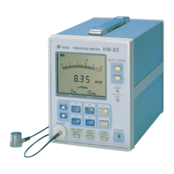
Outline The VM-83 is a vibration meter designed for measurement and evaluation of vibrations, using a piezoelectric accelerometer or a servo accelerometer. It pro- vides four types of input connectors and allows selection of acceleration, veloc- ity, and displacement measurement. With the optional servo accelerometer, even very low frequency vibrations in the range of 0.1 to 1 Hz can be measured,... - Page 12 www.64817.com Outline Block Diagram...
-
Page 13: Controls And Features
www.64817.com Controls and Features Front Panel V M - 8 3 V I B R A T I O N M E T E R L E V E L R A N G E D i s p l a y L E V E L R A N G E k e y s D i s p l a y c h a r a c t e r i s t i c s s e l e c t o r k e y... - Page 14 Controls and Features MENU key Allows changing the menu by selecting a menu number. If this key is pressed in remote control mode, the remote mode is canceled and the unit returns to the local mode. Power switch Serves to turn the unit on and off. COMP ON/OFF key Serves to turn the comparator function on and off.
-
Page 15: Rear Panel
Controls and Features Rear Panel Battery holder Four IEC R14 (size C) batteries are inserted here. Battery holder button Push this button to lock or unlock the battery holder. AC output connector An AC signal corresponding to the measurement value is available at this connector (full-scale point: 2 V, output impedance approx. - Page 16 Controls and Features Comparator output terminals The comparator signal is available at these terminals. The maximum applied voltage is 24 V, and the maximum drive current varies as follows depending on the impressed voltage. 50 mA (when the impressed voltage is 24 V) 25 mA (when the impressed voltage is 12 V) 10 mA...
-
Page 17: Side Panel
Controls and Features Side Panel G r i p F e e t P r o p - u p f e e t... -
Page 18: Display
Controls and Features Display For explanation purposes, the illustration below shows all display elements. In actual use, not all elements will be seen together. L e v e l r a n g e i n d i c a t o r C A L i n d i c a t o r C O M P i n d i c a t o r B a t t e r y c a p a c i t y... - Page 19 Controls and Features Units indicator The measurement unit applicable to the current measurement mode is shown here. When a piezoelectric accelerometer is used, this indicator ap- pears during acceleration measurement. mm/s When a servo accelerometer is used, this indicator appears during acceleration measurement.
- Page 20 Controls and Features UNDER indicator This indicator appears when the input signal has fallen below the measure- ment threshold. Battery capacity indicator Shows the remaining capacity of the batteries. F l a s h i n g S u f f i c i e n t r e m a i n i n g B a t t e r i e s R e p l a c e c a p a c i t y...
-
Page 21: Preparations
Preparations Power Supply This unit can be operated either on four IEC R14 (size C) batteries or an AC adapter (option). Inserting Batteries B A T T B O X Unlock the battery holder by pressing B a t t e r y h o l d e r B a t t e r y h o l d e r b u t t o n the battery holder button and pull out the battery holder. -
Page 22: Ac Adapter
Preparations Battery life Alkaline batteries LR14 approx. 20 hours Manganese batteries R14P approx. 9 hours * The above values were determined under the following conditions. 20°C 50% RH, accelerometer PV-85, ACC, HPF OFF, LPF OFF, back- light OFF, switch LEDs OFF, communications OFF (MENU 0-0), con- tinuous operation * The actual battery life will differ, depending on the accelerometer, set- tings, ambient conditions, and battery type. -
Page 23: Using The Prop-Up Feet
Important When using the prop-up feet, do not place ob- jects on top of the VM-83 and do not push down on the unit. D o n o t p u s h P r o p - u p f e e t... -
Page 24: Selecting An Accelerometer
Shear type Shear type *1 When mounted with specified screws at specified torque *2 Vertical direction value Servo accelerometer The servo accelerometer model that can be used with the VM-83 is the LS-10C or LS-20C. Model LS-10C LS-20C Voltage sensitivity (V/(m/s 0.300... -
Page 25: Connecting The Accelerometer
Direct connection Use the cable supplied with the accelerometer (VP-51 series) to connect the accelerometer to the ACCELEROMETER input connector on the VM-83. Because the input circuit is configured as a charge amplifier, accelerometer cable length has almost no effect on sensitivity. - Page 26 I N P U T S E R V O ( L S - 1 0 C ) P R E A M P connector on the VM-83. P I C K U P S E R I A L...
-
Page 27: Setting The Input Select Switch
Preparations Setting the INPUT SELECT Switch Set the INPUT SELECT switch as required for the type of input that is being used. ACCELEROMETER Signal from ACCELEROMETER connector on front panel PREAMP1 : Signal from PREAMP 1 connector on rear panel PREAMP2 : Signal from PREAMP 2 connector on rear panel SERVO... -
Page 28: Accelerometer Sensitivity Calibration
Preparations Accelerometer Sensitivity Calibration Important Different accelerometers have different sensi- tivity. Be sure to perform sensitivity calibration. Sensitivity calibration 1. Set the INPUT SELECT switch as required. 2. Set the power switch to ON. 3. Press the ACCELEROMETER SENS key on the front panel. (The indi- cator above the key lights up and the sensitivity value flashes.) V M - 8 3 V I B R A T I O N... - Page 29 Preparations 4. Use the setting keys ( , ) to set the display indication to the value indi- cated as charge sensitivity on the calibration chart of the accelerometer. C a l i b r a t i o n D a t a M o d e l S e r i a l N o .
-
Page 30: Measurement
Measurement Power-On When the unit is turned on, the same settings as used before the unit was turned off are reestablished (resume function), and measurement starts. The level range, high-pass filter setting, low-pass filter setting, and display characteristics are memorized for each measurement mode. Settings memorized by Settings reset at regular resume function... -
Page 31: Measurement Mode Setting
Measurement Measurement Mode Setting Select the measurement mode from ACC (acceleration), VEL (velocity), or DISP (displacement). Setting procedure 1. Press the ACC/VEL/DISP key. (The indicator above the key lights up.) C O M P R E M O T E U N D E R C A L O V E R... -
Page 32: Display Characteristics Setting
Measurement Display Characteristics Setting Select the display (detection) characteristics from RMS, EQPEAK, or EQP-P. Setting procedure 1. Press the RMS/PEAK/P-P key. (The indicator above the key lights up.) C O M P R E M O T E U N D E R C A L O V E R P E A K... -
Page 33: High-Pass Filter Setting
Measurement High-Pass Filter Setting Setting procedure 1. Press the HPF key. (The indicator above the key lights up.) C O M P R E M O T E U N D E R C A L O V E R P E A K M A X H O L D... -
Page 34: Low-Pass Filter Setting
Measurement Low-Pass Filter Setting Setting procedure 1. Press the LPF key. (The indicator above the key lights up.) C O M P R E M O T E U N D E R C A L O V E R P E A K M A X H O L D... -
Page 35: Level Range Setting
Measurement Level Range Setting Set the level range as follows. Use the setting keys ( , ) to select an appropriate level range. The relationship between INPUT SELECT switch, accelerometer sensitiv- ity, measurement mode, and HPF is shown in the table on the next page. - Page 36 Measurement When INPUT SELECT switch is set to ACCELEROMETER, PREAMP 1, or PREAMP 2 (*0 HPF: 1 Hz; *1 HPF: 3 Hz; *2 HPF: 10 Hz) Measurement Sensitivity Level range mode 1000 3000 10000 0.030 1000 3000 10000 DISP* 1000 3000 10000...
-
Page 37: Menu Settings
Measurement Menu Settings The settings for the serial interface, printer, peak hold function, and comparator function are made via menus. V M - 8 3 V I B R A T I O N M E T E R L E V E L R A N G E L I G H T C A L... - Page 38 Measurement 2. When the MENU key is pressed, a menu screen as shown below appears. With each push of the MENU key, the menu number cycles through 0 → 1 → 2 → 3 → 4 → 5 → 6 → 7 → 8 → measurement screen. M e n u n u m b e r S e t t i n g P E A K...
- Page 39 Measurement Menu 2 Serial interface ID number Choose a setting from 0 to 15. Menu 3 Peak hold function ON/OFF Peak hold function OFF Peak hold function ON Menu 4 Comparator function and comparator level Sets the comparator function and chooses a level between 0 and 98% of the full-scale value, in 2% steps.
- Page 40 Measurement Menu 8 Comparator output buzzer This controls buzzer use for the comparator function. When enabled, the buzzer sounds while the comparator output is active. When dis- abled, there is no buzzer sound also when the comparator output is active. Buzzer disabled Buzzer enabled Note...
-
Page 41: Calibration
Measurement Calibration When using external equipment to record the AC output signal or DC output signal of the VM-83, perform calibration as follows. V M - 8 3 V I B R A T I O N M E T E R... - Page 42 Measurement (1) When INPUT SELECT switch on rear panel is set to ACCELEROM- ETER, PREAMP 1, or PREAMP 2 AC output (AC OUT) : 80 Hz, 2 V* DC output (DC OUT) : 2 V (2) When INPUT SELECT switch on rear panel is set to SERVO SERVO AC output (AC OUT) : 1 Hz, 2 V * DC output (DC OUT) : 2 V...
-
Page 43: Maximum Value Hold
Measurement Maximum Value Hold This function serves for memorizing the maximum measured value. Setting procedure 1. Press the MAX HOLD ON/OFF key to set the function to ON. V M - 8 3 V I B R A T I O N M E T E R L E V E L R A N G E... - Page 44 Measurement 3. When the maximum hold value is higher than the overload threshold, the indication MAX HOLD OVER is shown. H O L D O V E R M A X P E A K k H z 4. The HOLD RESET key can be used to reset the maximum hold value at any time.
- Page 45 Measurement 5. Pressing the MAX HOLD key again turns the maximum hold mode off. The unit returns to normal measurement. Note While the maximum hold function is ON, all con- trols except the LIGHT key, MAX HOLD ON/OFF key, HOLD RESET key, and power switch are inac- tive.
-
Page 46: Peak Hold
Measurement Peak Hold The peak hold function uses 51.2 kHz sampling on the vibration input signal to determine the peak value. Setting procedure 1. Use the MENU key to call up menu 3. 2. Use the setting keys to select the setting 3-1 (peak hold ON). P E A K H O L D k H z... - Page 47 Measurement Note The peak hold function applies only to the numeric display. The bar graph indication continues to func- tion as during normal measurement. While the peak hold function is ON, all controls ex- cept the LIGHT key, MENU key, HOLD RESET key, and power switch are inactive.
-
Page 48: Comparator
Comparator Comparator operation The comparator works by constantly monitoring the measured vibration level and comparing it to a preset reference level (comparator level). If the compara- tor level is exceeded, the comparator output becomes active (open collector circuit, LCD flashing, buzzer sounds). To turn the comparator function on and off, use the COMP ON/OFF key. - Page 49 Comparator L i t C O M P m / s P E A K k H z While comparator function is operating, the COMP indicator is shown. In the bar graph indication, the bar corresponding to the comparator reference level remains constantly on.
- Page 50 Comparator Auto reset function The auto reset function is controlled with menu screen 6 (see "Menu Settings" on page 27). When the function is set to ON and the vibration level has fallen again below the comparator level, the comparator output will automatically be reset (turned off) after the auto reset time has elapsed.
- Page 51 Comparator Operation Reset operation When the comparator output was activated, it can be reset in three ways. (1) Auto reset As described above, when auto reset is ON, the comparator output will be turned off automatically after activation when the auto reset time has elapsed.
- Page 52 Comparator Comparator output The comparator output has three elements. (1) Buzzer is heard (long intermittent beeps). This applies only if the buzzer function has been set to ON with menu 8. (2) LCD display flashes. Measurement value indicator section flashes in 0.5 second intervals. (3) Open collector circuit operates, causing the comparator output terminals on the rear panel to close.
-
Page 53: Printer
Activating printer operation 1. Turn power to the VM-83 and the printer off. 2. Use a separately purchased cable to connect the serial interface connector on the rear panel of the VM-83 to the printer (option). Cable: Straight serial cable (generic) - Page 54 Printer Stopping printer operation 1. Using the menu screens, select the menu setting 0-0. 2. Disconnect the cable. Note printer operation is paused during calibration, com- parator operation, sensitivity setting, and while us- ing the menu screens. DIP switch settings for printers CP-11, CP-10 Set the DIP switches for the respective printers as shown below.
- Page 55 When connecting the printer DPU-414, set the DIP switches 1 to 3 for the printer software as follows. For more information on making these settings, please refer to the instruction manual and the guide sheet of the DPU-414. Vibration Meter VM-83 (9600 bps) SW-1 SW-2...
- Page 56 Printer Printout sample A C C m / s s R M S 1 0 0 0 H P F 1 H z L P F 3 k H z = O V # = U N 1 2 7 1 0 0 6 7 3 9 3 1 1...
-
Page 57: Serial Interface
Serial Interface The VM-83 incorporates a serial interface that can be used to set measurement parameters and control measurement using commands sent from a computer. Measurement results can also be sent to the computer. Using SC-31M or SC-31S adapters (option), a single computer can be used to control up to 16 VM-83 units. -
Page 58: Local Mode/Remote Mode
Serial Interface Local Mode/Remote Mode Local mode In this mode, the controls on the panel of the VM-83 are used to operate the unit. Immediately after being turned on, the unit is always in local mode. Remote mode In this mode, the VM-83 operates in response to commands sent from a computer. - Page 59 C r o s s - w i r e d s e r i a l c a b l e ( n u l l m o d e m ) 1:N connection When wishing to connect multiple VM-83 units (up to 16) to one com- puter, the optional SC-31M/SC-31S adapters and LAN cables (generic 10BaseT cable) are required.
- Page 60 Serial Interface 3. Set the power switch of the VM-83 to ON. 4. Make the required menu settings at the VM-83. For details, please refer to "Menu Settings" on page 27. Menu 0-1 Menu 1-96 or 1-19 Set transfer rate.
-
Page 61: Transfer Protocol
Transfer Protocol Sending of commands In order to control the VM-83 from a computer or to retrieve measurement data, certain commands must be sent to the VM-83. The data exchange must be per- formed according to certain rules, to ensure that both the VM-83 and the com- puter recognize the commands and data properly. - Page 62 Serial Interface C o m p u t e r V M - 8 3 R M T 1 < C R > < L F > L i n k e s t a b l i s h e d <...
-
Page 63: Error Processing
Control Operation in Remote Mode While the VM-83 is in remote mode, only the LIGHT key and MENU key are active. The LIGHT key allows turning the display backlight on and off, and the MENU key in remote mode serves for switching back to local mode. This al-... -
Page 64: Command Format
Serial Interface Command Format Commands that can be used by the VM-83 consist of 3 characters (3 bytes), usually followed by a parameter which specifies the action range of the com- mand. < C R > < L F >... - Page 65 Serial Interface Command List Command Function See page RMT n1 n2 n3 Select local mode/remote mode RMT? Get ID number and remote mode status RNG n Set level range UNT n Set measurement mode DET n Set display characteristics SNS n1 n2 n3 n4 Set sensitivity LPF n Set low-pass filter setting...
- Page 66 Local mode n1 = 1 Remote mode n2 n3 = 00 to 15, FF Sets ID number. VM-83 specified by ID number receives the command. FF specifies all connected VM-83. RMT? Get ID number and remote mode status Output data format p1 p2 p3<EOT><CR><LF>...
- Page 67 Serial Interface When INPUT SELECT is set to ACCELEROMETER, PREAMP1, PREAMP2 (*0 = HPF 1 Hz, *1 = HPF 3 Hz, *2 = HPF 10 Hz and higher) Measurement Sensitivity n =0 n = 1 n = 2 n = 3 n = 4 n = 5 n = 6...
- Page 68 Serial Interface DET n Set display characteristics n = 0 n = 1 EQPEAK n = 2 EQP-P SNS n1 n2 n3 n4 Set sensitivity n1 to n3 : Set sensitivity to 030 to 999 n4 = 0 : Set sensitivity to 1/10 of value specified with n1 to n3 n4 = 1 : Set sensitivity to 1/100 of value specified with n1 to n3...
- Page 69 Serial Interface LPF n Set low-pass filter setting Command action depends in INPUT SELECT switch setting. Piezoelectric accelerometer : ACCELEROMETER, PREAMP1, PREAMP2 Servo accelerometer SERVO , SERVO Piezoelectric Servo n = 0 n = 1 n = 2 n = 3 n = 4 10 k n = 5...
- Page 70 Serial Interface CAL n Set calibration mode. n = 0 Calibration OFF n = 1 Calibration ON CAL? Get calibration mode status Output data format p<EOT><CR><LF> p = 0 Calibration OFF p = 1 Calibration ON BAT? Get battery capacity status Output corresponds to status of battery capacity indicator on display.
- Page 71 Serial Interface * When operating in maximum hold mode, returned value corresponds to MAX HOLD value. Same applies to peak hold mode. When this command is received while there is no display indication, output will be p1 to p4 = 0000. DOF n Output instantaneous value every 0.1 seconds in non-pro- tocol mode...
- Page 72 Serial Interface MAX n Set maximum hold function to On/Off n = 0 Maximum hold OFF n = 1 Maximum hold ON MAX? Get maximum hold function status Output data format p<EOT><CR><LF> p = 0 Maximum hold OFF p = 1 Maximum hold ON PEK n Set peak hold function to On/Off...
- Page 73 Serial Interface CMS n1 n2 n3 n4 n5 n6 n7 Make comparator function settings n1 to n2 : Comparator level 00 to 98 (steps of 2) : Delay time 0 to 9 n4 = 0 : Auto reset OFF n4 = 1 : Auto reset ON n5 to n6 : Auto reset time 00 to 90 (steps of 10) n7 = 0 : Buzzer OFF n7 = 1 : Buzzer ON...
- Page 74 Serial Interface STS? Get setting information Output data format p1 p2 p3 p4 p5 p6 p7 p8 p9 p10<EOT><CR><LF> INPUT SELECT 0 to 4 p1 = 0 : ACCELEROMETER in- p1 = 1 : PREAMP 1 input p1 = 2 : PREAMP 2 input p1 = 3 : SERVO input p1 = 4 : SERVO input...
- Page 75 Serial Interface Allowable remote mode commands in various operation conditions indicates that command is allowed (valid). × indicates that command is not allowed (invalid). Normal Maximum Peak Command Calibration Comparator Explanation measurement hold hold operation RMT n1n2n3 Cancel remote mode RMT? ×...
-
Page 76: Communication With Multiple Units Using Sc-31M/Sc-31S
Communication with Multiple Units using SC-31M/SC-31S Using the optional SC-31M/SC-31S adapters, it is possible to connect up to 16 VM-83 units to a single computer. Connecting multiple VM-83 units (max. 16) to a computer Use SC-31M/SC-31S adapters (option) and LAN cables (generic 10BaseT cable) - Page 77 To send a command to a single unit when multiple units are connected, the same procedure as for one-on-one communication is used. 1. Verify that all connected VM-83 units are set to local mode. 2. Send the RMT1**<CR><LF> command, where ** is the ID number of the unit to be controlled.
- Page 78 When sending commands to all connected units, only commands for changing settings are allowed. To address a command to all units, set all units to remote mode by sending the RMT1FF command. Note that a VM-83 that has received the RMT1FF command will not output a response to any command.
-
Page 79: Technical Information
Technical Information Noise Level and Measurement Range (1) Noise level using accelerometer input and sensitivity 5.00 pC/(m/s Measurement Measurement Display Noise level mode range characteristics Acceleration 0.004 m/s Velocity 1 Hz 0.1 mm/s Displacement 1 Hz 0.015 mm Displacement 0.03 10 Hz 0.0003 mm (2) Noise level examples using servo accelerometer input... - Page 80 Technical Information (3) Measurement range with servo accelerometer LS-10C Acceleration measurement range 1 0 0 0 0 5 0 0 0 2 0 0 0 1 0 0 0 5 0 0 2 0 0 1 0 0 0 . 5 0 .
- Page 81 Technical Information Velocity measurement range...
- Page 82 Technical Information Displacement measurement range 1 0 0 0 . 5 0 . 2 5 3 m m 0 . 2 0 . 1 0 . 0 5 0 . 0 2 0 . 0 1 0 . 0 0 5 0 .
-
Page 83: Group Delay
A C o u t p u t s i g n a l a p p r o x . 6 0 0 µ s Rack Mounting The VM-83 can be mounted in a rack, using the four screw holes on the bottom of the unit. F r o n t... -
Page 84: Accelerometer Installation
Technical Information Accelerometer Installation The accelerometer can be mounted to the measurement object in one of the four general ways outlined below. The accelerometer mounting method greatly af- fects the contact resonance frequency *. The advantages and disadvantages of various methods are described in this section. Rigid screw mounting This mounting principle assures optimum frequency re- sponse characteristics. - Page 85 Technical Information * Contact resonance frequency Contact resonance occurs when the area the mounted accelerometer con- tacts the measurement object becomes temporarily deformed, causing it to act like a spring. This spring and the accelerometer mass then form a system that vibrates at a certain resonance frequency.
-
Page 86: Display Range
0.1 to 300.0 0.01 to 90.00 The VM-83 directly feeds the raw waveform of the vibration signal to an A/D converter and then performs filter processing, rms conversion, and other func- tions using a DSP. When the number of effective digits for display decreases, display accuracy cannot be maintained. -
Page 87: Aliasing Effect
An anti-aliasing filter (ana- log low-pass filter) serves to counter this effect. In the VM-83, a 5th-order filter is used for this purpose. Note that the filter has the effect shown below. -
Page 88: Filter Characteristics
Technical Information Filter Characteristics Piezoelectric accelerometer High-pass filter - 1 0 - 2 0 O F F - 3 0 - 4 0 1 H z 3 H z 1 0 H z 2 0 H z 5 0 H z - 5 0 0 . - Page 89 Technical Information Servo accelerometer LS-10C High-pass filter 0 . 1 H z - 1 0 - 2 0 - 3 0 - 4 0 0 . 3 H z 1 H z - 5 0 0 . 0 2 0 . 0 5 0 .
-
Page 90: Vm-83Pb1 Software
VM-83PB1 is a software package for Microsoft Windows 95, 98, 98SE, Me, 2000, XP and Microsoft Windows NT4.0 which allows controlling settings and measurement operation of the VM-83 from the computer, via the serial port. Measurement data downloaded from the VM-83 can be stored in text file format, allowing further processing for example using a spreadsheet pro- gram. -
Page 91: Specifications
Specifications Input Section (1) ACCELEROMETER input For piezoelectric accelerometer (microdot connector) Maximum input charge 30000 pC (2) PREAMP 1 input For piezoelectric accelerometer via preamplifier VP-26A (7-pin female connector PRC-03) (3) PREAMP 2 input For piezoelectric accelerometer with integrated preamplifier 18 V, 2 mA drive (microdot connector) (4) SERVO input For servo accelerometer LS-10C or LS-20C... - Page 92 Specifications Accelerometer sensitivity 1.00 to 9.99 pC/(m/s Acceleration 0.3, 1, 3, 10, 30, 100, 300, 1000 m/s Velocity 3, 10, 30, 100, 300, 1000 mm/s Displacement 1, 3, 10, 30, 100, 300, 1000 mm (HPF 1 Hz) Displacement 0.3, 1, 3, 10, 30, 100, 300, 1000 mm (HPF 3 Hz) Displacement 0.03, 0.1, 0.3, 1, 3, 10, 30, 100 mm (HPF 10 Hz or higher)
- Page 93 Specifications Filters Piezoelectric accelerometer OFF, 1, 3, 10, 20, 50 Hz (-10% point), selectable OFF, 100, 300, 1 k, 3 k, 10 kHz (-10% point), selectable Servo accelerometer 0.1, 0.3, 1 Hz, selectable 50, 100 Hz, selectable Display (detection) characteristics Effective value (RMS) True rms Equivalent peak (EQ PEAK)
- Page 94 Specifications Display functions (1) Bar graph, linear scale, 100 ms sampled value 0 to 3.16 0 to 10 (2) 4-digit numeric display; arithmetic average of 20 instantaneous values taken at 100 ms intervals, updated every 2 seconds (3) Measurement mode, display characteristics, filter (4) Battery status;...
- Page 95 Specifications Outputs (1) AC output; full-scale 2 V, output impedance 600 Ω, BNC connector Load impedance: 10 kΩ or higher Output voltage accuracy Piezoelectric (unit electrical characteristics, 80 Hz) Velocity: range full-scale ±2% Acceleration: range full-scale ±3% Displacement: range full-scale ±5% Servo accelerometer (overall accuracy with LS-10C 1 Hz) Velocity: range full-scale ±3%...
- Page 96 Specifications Noise level (1) Noise level with accelerometer input, sensitivity 5.00 pC/(m/s Measurement Measurement Display Noise level mode range characteristics Acceleration 0.004 m/s Velocity 1 Hz 0.1 mm/s Displacement 1 Hz 0.015 mm Displacement 0.03 10 Hz 0.0003 mm (2) Noise level example with piezoelectric accelerometer Measurement Measurement Display...
- Page 97 Specifications (3) Measurement range with servo accelerometer LS-10C Acceleration measurement range 1 0 0 0 0 5 0 0 0 2 0 0 0 1 0 0 0 5 0 0 2 0 0 1 0 0 0 . 5 0 .
- Page 98 Specifications Velocity measurement range...
- Page 99 Specifications Displacement measurement range 1 0 0 0 . 5 0 . 2 5 3 m m 0 . 2 0 . 1 0 . 0 5 0 . 0 2 0 . 0 1 0 . 0 0 5 0 .
- Page 100 9-pin D-sub male connector Half-duplex communication with protocol Transfer rate 9600, 19200 bps SC-31M/SC-31S (option) allow connection of multiple VM-83 units (max.16) to one computer. Maximum allowable wiring distance: 400 m Printer output For data output to printer (CP-10, CP-11, DPU-414)
- Page 101 Vibration level meter accelerometer cable EC-02 series Servo accelerometer LS-10C, LS-20C Servo accelerometer cable EC-40 series Calibrator VE-10, VE-20 VM-83 management software VM-83PB1 (for Windows 95, 98, 98SE, Me, 2000, XP and Windows NT4.0) Printer DPU-414 Multi-channel adapter M SC-31M...
-
Page 102: Dimensional Drawing
www.64817.com Specifications V M - 8 3 V I B R A T I O N M E T E R L E V E L R A N G E L I G H T C A L H P F L P F R H S A C C / V E L... -
Page 103: Index
Index calibration mode ......55 CMP n ........55, 62 AC adapter ........12 CMP? ..........55 AC output connector ......5 CMS n1 n2 n3 n4 n5 n6 n7 ..55, 63 Acceleration measurement range CMS? ........55, 63 .......... - Page 104 www.64817.com Index Low-pass filter key ......4 LPF n ........55, 59 equivalent peak ......8, 22 equivalent peak-to-peak ....8, 22 Error Processing ......53 MAX HOLD ON/OFF key ....4 external power supply connector MAX n ........55, 62 ............
- Page 105 www.64817.com Index Power requirements ......90 setting information ......55 Power switch........4 Setting keys ........4 PREAMP 1 input ......81 SNS n1 n2 n3 n4 ....... 55, 58 PREAMP 2 input ......81 STS? ......... 55, 64 preamplifier ........15 Preamplifier 1 input connector ..
- Page 106 No. 31185 06-06 Printed in Japan...
Need help?
Do you have a question about the VM-83 and is the answer not in the manual?
Questions and answers