Table of Contents
Advertisement
Quick Links
Advertisement
Table of Contents

Related Manuals for GRAVOGRAPH LS900 Fibre


Summary of Contents for GRAVOGRAPH LS900 Fibre
- Page 1 OPERATING AND MAINTENANCE MANUAL LS900 Fibre LS900 Edge MARKING LASER...
-
Page 2: Table Of Contents
Table of contents A. Foreword ..............................5 1. Appreciation ............................5 2. Information ............................. 5 B. Legal notices ............................6 C. Regulation observance ..........................7 D. Required safety labels ..........................8 E. Introduction ............................10 1. Presentation ............................10 2. Identification of the marking equipment ....................10 3. Work station safety .......................... - Page 3 H. Description of the machine ........................21 1. Front view of the machine ........................21 2. Rear view of the machine ........................22 Recommendations for installation ....................... 23 1. Physical installation ..........................23 2. Air extraction system (option) ........................ 25 „ Head mode (option: suction hose) ...................... 26 3. Air assist (option: air compressor) ......................27 4. IT requirements ............................ 28 5. Software compatibility ..........................
- Page 4 M. Adaptable accessories .......................... 45 1. Cylinder attachment ..........................45 2. Tilting base for rotary device ........................ 45 3. Extra pair of glasses ..........................45 4. Compressor kit (air assist)........................46 5. Honeycomb cutting table ........................46 6. Cutting out kit ............................47 N. Preventive maintenance ........................48 1. General maintenance ........................... 48 2. Accessories provided ...........................
-
Page 5: Foreword
A. Foreword 1. Appreciation Thank you for choosing LS900 Fibre - LS900 Edge - Gravograph. Gravotech is pleased to count you among the users of its engraving and traceability solutions. For help, contact Gravotech. For more information on products, visit www.gravograph.com website. 2. Information To ensure security and productivity, read this manual before starting-up the equipment. It provides details about the installation and use of the equipment. Keep this manual in case you need to refer to it. -
Page 6: Legal Notices
Product with applicable rules and standards. Shall the Product be non-compliant, the person in charge of the Product's installation shall be responsible of the final workstation's compliance. In no event, Gravotech shall be liable for any damages arising from such non-recommended or unauthorized Product's alterations. It is precised that the warranty shall not apply in such case. Under no circumstances shall Gravotech be held liable for any indirect, incidental, special, consequential punitive or other similar damages, including any economic loss, loss of profit, loss of data or opportunity, whether or not foreseeable by or communicated to Gravotech, caused by this manual or the supply of Products or services concerned by the said manual. To the widest extent permitted by law, Gravotech shall only be held liable for direct damage arising from personal injury caused by a fault proven in its Product (including this manual). Gravotech® - Type3® - Propen™ - Technifor™ - Gravograph® is (are) a used, pending or registered trademark(s) of Gravotech group or one of its subsidiaries. The products and names of third party companies which appear in this manual are used solely for the necessary purposes of reference, and in particular for issues of compatibility. All the trademarks mentioned in this manual remain the property of their respective owners. Windows® is (are) a used, pending or registered trademark(s) of Microsoft Corporation. Postscript® is (are) a used, pending or registered trademark(s) of Adobe Systems Incorporated. M_LS900 Fibre - LS900 Edge_EN_C... -
Page 7: Regulation Observance
- EMC: 2014/30/EU - RoHS 2: 2011/65/EU - Cells and batteries: 2006/66/EC CO2, Yag and fiber laser marking: Machine (gantry) - Machinery: 2006/42/EC LS100 Energy, LS100 Ex Energy, LS900 Energy - Low voltage: 2014/35/EU LS100, LS100 Ex, LS900, LS900 XP, LS1000XP - EMC: 2014/30/EU LS100 Ex Fibre, LS900 Fibre - RoHS 2: 2011/65/EU LS900 Edge - Safety of laser products - Part 1: Equipment classification and CO2, Yag and fiber laser marking: Machine (galvo) requirements: EN 60825-1:2008 LW1, LW2 - Safety of laser products - Part 4: Laser guards: EN 60825-4+A1+A2:2006 Laser Solution Hybrid-Series (Energy), Laser Solution Green-Series (Energy), Laser Solution CO2-Series (Energy) CO2, Yag and fiber laser marking: Partly completed machinery (galvo) –... -
Page 8: Required Safety Labels
Warning: Flammable LS100 Energy materials LS900 LS900 XP LS1000 XP Warning: Hot surface Warning: Flammable materials LS100 Ex Fibre LS900 Fibre Warning: Hot surface LS900 Edge Laser Solution Fiber-Series (Energy) Laser Solution Hybrid-Series (Energy) Laser Solution Green-Series (Energy) M_LS900 Fibre - LS900 Edge_EN_C... - Page 9 Required safety labels Required safety labels Laser Solution -Series (Energy) LW1 - LW2 (LaserTop 2000) M_LS900 Fibre - LS900 Edge_EN_C...
-
Page 10: Introduction
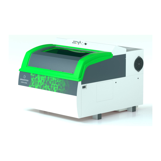
E. Introduction 1. Presentation The LS900 Fibre is a marking machine equipped with a fiber-type laser source. This type of laser offers very high quality marking on a wide range of materials. The LS900 Edge machine has 2 laser source(s): fiber, CO . It allows an even wider range of materials to be marked. 2. Identification of the marking equipment The marking equipment is identified by: • 1 identification plate on the rear face Have the model and serial number of the equipment available when contacting Gravotech. 3. Work station safety • Turn off the machine before beginning any cleaning, maintenance or repair procedure. • Never operate the machine without the protective covers properly mounted. • Never operate the machine if the doors are damaged or do not close properly. „ Air extraction system Never operate the machine without a fume and gas extraction system that is properly configured, •... -
Page 11: Unpacking
F. Unpacking The machine should be carried in its packaging using a lifting system that can lift 300 kg (661.387 lb) or more. 1. Unpacking 1. Cut and remove the packaging straps. 2. Remove the accessories package, protective wrappers and cardboard box. 3. -
Page 12: Package Contents
Unpacking 2. Package contents Machine: LS900 Fibre / LS900 Edge CD-ROM containing the machine driver DVD containing the instruction manual 4. Toolbox Power cable USB cord Toolbox: content 1 bottle(s) of cleaning solution 1 packet(s) of lens cleaning wipes 1 packet(s) of cotton buds for mirrors 4. Driver Ball-tip hex key Brush Set of 6 keys Compressed air hose for air assist (length: 100 mm (3.937 in) - tube diameter: 4 mm (0.157 in)) M_LS900 Fibre - LS900 Edge_EN_C... -
Page 13: Laser Safety
G. Laser safety 1. Recommendations and safety regarding laser devices „ Personnel safety THIS MACHINE HAS A CLASS 4 LASER BOXED IN A CLASS 1 CASING. THIS MACHINE IS CONSIDERED AS CLASS 2M DUE TO ITS VISIBLE DIODE LASER (red). • machine considered Class when door closed. In this case, the security enclosure of the LS900 Fibre / LS900 Edge is locked and sealed against potential Laser radiation emissions under normal working and safety conditions. The modification of locking systems, or the removal of these systems or labels designed for safety, will result in exposure to hazards... -
Page 14: Using The Pass Through Kit - Class 4
Laser safety 2. Using the Pass through kit - Class 4 If one of these removable hatches is removed, the machine is no longer considered to be Class 1 (in a secure zone) but Class 4. A controlled laser zone should be defined. Operators and service personnel must receive laser safety training. Carefully read the "Laser Safety" chapter. For help, contact Gravotech. It is mandatory that the operator wear eye protection with the suitable filter lenses (LS900 Fibre: IR LB6 - 1064 nm, LS900 Edge: IR LB6 - 1064 nm + D LB4 - 10600 nm). Any person standing in proximity to the laser must obey the same safety instructions. -
Page 15: Work Station Safety
Laser safety 3. Work station safety „ Proposed warning label at the entrance to the laser controlled zone (using the Pass through kit - class 4) Specific hygiene and safety instructions _________________________________________ Personnel laser radiation protection Concerned industrial use installation: Use: Installation: Restricted area The room in which this sign is posted is defined as a restricted laser area: • in normal production phase: using the Pass through kit - class 4 (1) • maintenance and setting phase (1) • ................(1) Regulation in the restricted area Access to the restricted laser area is regulated. Only competent personnel having attended proper training can remain during the operation: this implies medical aptitude and laser safety training. -
Page 16: X84; General Instructions
Laser safety „ General Instructions Avoid any exposure to laser radiation. Do not put hands or an object in the laser beam's trajectory. Never stare into the primary laser beam. Avoid direct eye exposure to diode laser beam. Do not direct the beam towards other persons, openings or windows. Do not remove protection hoods or short-circuit the securities. Electrical interventions on the system can only be carried out by competent LT/HT personnel. -
Page 17: Optical Components (Only For Ls900 Edge Machines)
Laser safety 4. Optical components (only for LS900 Edge machines) „ Safety precautions The various optics included in this machine contain ZnSe (zinc selenide). When handling the optics, protective gloves should be worn. • Particular attention is required when handling, fixing and cleaning these elements. • Do not apply uneven pressure. • The entire optical system (mirrors and lenses) in the beam guiding zone must be cleaned regularly. • Do not use hard objects or tools to clean the surface. •... -
Page 18: X84; Protective Measures In The Event Of A Broken Lens
Laser safety „ Protective measures in the event of a broken lens If a lens has been damaged or cracked during an operation, precautions must be taken to remove and clean it. 1. As soon as an unpleasant smell is detected, switch off the machine. 2. Hold your breath. 3. Leave the vicinity of the machine. 4. Wait for at least 30 minute(s) for the chemical reaction to run its course. 5. Wear appropriate protective clothing (respiratory protection, safety glasses, protective clothing, rubber or plastic gloves). -
Page 19: Potential Hazards Related To Materials Worked With
Laser safety 5. Potential hazards related to materials worked with „ Fumes and toxic particles Laser marking certain materials emits dangerous fumes particles that may be toxic and/or damage the equipment. In this case, adapt an extraction system (with filtration if necessary) to the marking station. The user must check the compatibility of marked or engraved materials with the laser type. -
Page 20: X84; Examples Of Secondary Radiation Risks
Laser safety „ Examples of secondary radiation risks The use of a class 4 laser device can generate: • a risk of fire or explosion due to materials or inflammable substances • UV radiation • X rays • high intensity visible light when marking on certain materials M_LS900 Fibre - LS900 Edge_EN_C... -
Page 21: Description Of The Machine
H. Description of the machine 1. Front view of the machine LCD screen Keyboard Green light - Red light 4. Control panel Head (LS900 Fibre: red / LS900 Edge: gold) Guide rails: Y Ruler: Y "Pass through" hatches Rotary device connection (optional) 10. Air assist: Adjustment button 11. Guide rails: X 12. Frame 13. Ruler: X 14. Engraving table 15. -
Page 22: Rear View Of The Machine
Description of the machine 2. Rear view of the machine Each connection meets one of the following safety levels: • dangerous voltage • SELV (safety extra-low voltage) View of connectors Power inlet / outlet - Dangerous voltage Opening for air evacuation hose to air extraction system Air assist: pneumatic connection for tube 4. Input/output link: air extraction system - SELV Port: USB: Print and Cut - SELV Standard input/output link - SELV Do not use (the protective cap should not be removed under any circumstances) Port: USB: connection to computer - SELV To avoid the risk of electrocution, always unplug the power cable before removing the protective cover. -
Page 23: Recommendations For Installation
I. Recommendations for installation The physical installation and connections must be done by a Gravotech approved technician. Turn off the machine before any intervention (put the On/Off switch in the "O" (Off) position). On / Off switch 1. Physical installation • Place the machine on a horizontal, stable and clean surface that can support 170 kg (374.786 lb) or more. • Check that the engraving table is level in both directions (adjust with a spirit level). • Place the machine in a clean, ventilated environment. Choose the location that offers the shortest and most direct route to the air extraction system (see: Air extraction system (option). • Avoid small, confined, unventilated spaces. Some materials continue to emit gases for a few minutes after laser marking or cutting. The presence of these materials in a confined, unventilated room could contaminate the room. - Page 24 Recommendations for installation The machine is fitted with fans which cool the laser source and the electronics during operation. Check that the temperature is indeed between 10 °C (50 °F) and 35 °C (95 °F). Ventilator This marking equipment is designed to function at a room temperature between 10 °C (50 °F) and 35 °C (95 °F). • If the equipment is stored at a temperature inferior to 10 °C (50 °F) or superior to 40 °C (104 °F), leave it 24h at a temperature between 10 °C (50 °F) and 35 °C (95 °F) before start-up. • Ambient light is enough to light the equipment properly. The machine has a lighting system inside the work area. • Arrange the work area so that the operator can quickly and easily access all the external parts of the machine. Do not obstruct the movement of the moving parts of the machine.
-
Page 25: Air Extraction System (Option)
Recommendations for installation 2. Air extraction system (option) Never operate the machine without a fume and gas extraction system that is properly configured, installed and maintained in good working order. Laser marking certain materials emits dangerous fumes and fine particles that may damage health. Call an approved supplier to install an extraction system that complies with safety requirements and local regulations. -
Page 26: X84; Head Mode (Option: Suction Hose)
Recommendations for installation „ Head mode (option: suction hose) Before selecting head mode, install the suction hose on the machine. Install the hose only for engraving work at slow speeds of movement (maximum: 1 m/s). At high speeds, it could be pulled off and damage the machine. Suction hose: installation 1. Remove the protective cap on top of the head. Gently install the hose in place of the cap. Do not press too hard on the head, otherwise it could be displaced or damaged. Protection cap(s) Suction hose (optional) Tube... -
Page 27: Air Assist (Option: Air Compressor)
Recommendations for installation 3. Air assist (option: air compressor) The operation of the air assist system (blown air) requires the use of an air compressor (not supplied). Configuration: Air flow rate: 12.4 l/min (minimum) Use the compressed air hose supplied to connect the machine to the air compressor. Connector (air compressor) M_LS900 Fibre - LS900 Edge_EN_C... -
Page 28: It Requirements
Recommendations for installation 4. IT requirements Hardware Minimum configuration of the PC Recommended configuration Microprocessor Dual Core Quad Core Frequency 2.7 GHz 2.4 GHz 2 Go / GB 4 Go / GB Hard disk 3 Go / GB available 6 Go / GB available DVD: internal drive 16X DVD-ROM 16X DVD-ROM 2 button(s) 2 button(s) + thumbwheel - Mouse Windows®-compatible Windows®-compatible Keyboard Windows®-compatible Windows®-compatible 2 USB port(s) available: 4 USB port(s) available: - protection key - protection key... -
Page 29: Electrical Installation
Avoid the installation of manual or automatic switching systems on the same mains power line as the machine (relays, timers, programmers, automatic circuit-breakers, automatic switches, etc.). • Check that devices in the vicinity of the machine meet the standards for electromagnetic interference. Read the technical data sheet for each device. If they are non-compliant, move them as far away from the machine as possible. • Use the Gravograph accessories. Always switch the machine off before connecting or disconnecting a cable or optional accessory. M_LS900 Fibre - LS900 Edge_EN_C... -
Page 30: Connections - Installation
J. Connections - Installation 1. Unblocking the head (shipping position) To protect the head during shipping, it is immobilized using 2 elastic band(s). Remove them before operating the machine. Elastic band(s) M_LS900 Fibre - LS900 Edge_EN_C... -
Page 31: Power Supply Connection
Connections - Installation 2. Power supply connection Rear view of the machine Power inlet / outlet - Dangerous voltage Input/output link: air extraction system - SELV Standard input/output link - SELV 1. Connect the machine/extraction system link cable on both sides. 2. Lock the integrated twist lock of the extraction system connector by hand. Make sure the connector screws are properly tightened to prevent the cables from becoming disconnected while the machine is switched on. -
Page 32: X84; Using The Plc Function (User Standard Inputs/Outputs)
Connections - Installation „ Using the PLC function (user standard inputs/outputs) Before making any "user standard input/output" connections, check that the electrical and electronic characteristics of the different inputs and outputs are respected. Incorrect connection could permanently damage the machine electronics. Using the PLC function means that it is not just a matter of considering the machine on its own in order to ensure operator safety. The machine becomes part of a larger process (automated line). Consequently, the whole final workstation (machine + PLC + loading system) needs to meet regulatory safety requirements. In this case, the machine and equipment installer is responsible for the final work station's compliance. - Page 33 Connections - Installation Input / Output characteristics (Sub-D15 connector) Number Function Type Comments Output NPN Maximum current: 50 mA Output NPN Maximum current: 50 mA Output NPN Maximum current: 50 mA Output NPN Maximum current: 50 mA Available for powering the loads Maximum current: 200 mA switched by the NPN outputs (O1 - Dry contact TTL-compatible Input Dry contact TTL-compatible...
- Page 34 Connections - Installation Example of wiring for an Input (I1) Control Unit Example of wiring for an Output (O1) - 24 V inductive load Control Unit Example of wiring for an Output (O1) - 5 V inductive load Control Unit When connecting inductive charges use an anti-parasite protection and a freewheeling diode to avoid damaging the Outputs. M_LS900 Fibre - LS900 Edge_EN_C...
-
Page 35: X84; Switching On The Machine
Connections - Installation „ Switching on the machine Place the switch in the "I" position (On). The screens must follow on from one another: SET UP FPGA << GRAVOGRAPH >> FPGA X.XX LCD SOFT X.XX 32 Mo BOOT X.XX <READY TO RECEIVE > The machine is ready for operation. Do not load files until the display says "Ready to receive". This could cause incorrect loading of the file. Loading a damaged file could cause incorrect laser emission, which could damage the engraving machine. -
Page 36: X84; Power Down
Connections - Installation „ Power down Put the On/Off switch in the "O" (Off) position. Switch off the machine in the following situations: • when the operator is permanently leaving the machine • in the event of physical damage (something is dropped on the machine, fire, a liquid is spilled on the machine, etc.) • mechanical/electrical/electronic faults suggesting a breakdown • if there is a major problem or the machine is jammed mechanically • forced restart • external/internal cleaning •... -
Page 37: Machine / Pc Connection
Connections - Installation 3. Machine / PC connection The machine installation and usage procedure is based on a PC-type computer running Windows®. For help, contact Gravotech. Switch off the PC and the machine. Follow the connection procedure for the type of link cable supplied with the machine. The machine is supplied with a USB cable. „ Machine / PC connection (USB connection) 1. Connect the USB cable to the machine's USB port. 2. Connect the USB cable to the PC's USB port. M_LS900 Fibre - LS900 Edge_EN_C... -
Page 38: Operating Instructions For The Machine
K. Operating instructions for the machine The machine control panel is used to easily access to all the controls for cutting and engraving/marking. 1. Control panel "Check" key Air assist Selecting a(n) file 4. Start - Start marking Joystick Green light - Red light Cancel Autofocus Positioning pointer 10. Pause 11. Focus adjustment M_LS900 Fibre - LS900 Edge_EN_C... - Page 39 Operating instructions for the machine Access to the different menus Exit from current menu "Check" key Move to next screen Move to next menu Validation of the entered data Air assist Activation of air assist during marking Selecting a(n) file Display of next file in machine memory, which becomes current file Start Start-up marking Start marking Head movement (X, Y, Z) Joystick Move the cursor to different data entry areas Green light - Red light See: Indicator light(s) Exit from menu without applying change to last parameter Cancel Return to reception, during a pause, during end of reception, during end of engraving Autofocus Automatic focus adjustment (automatic Z Ref.)
-
Page 40: X84; Indicator Light(S)
Operating instructions for the machine „ Indicator light(s) The status of the lights varies depending on the machine activity. Green light Status Description Machine initializing End of file processing and return to original position Machine ready to receive a file Off Interruption during file processing Pause Red light Status Description Machine initializing Machine ready to receive a file Off Pause Flashing Marking in progress 2. Description of the human-machine interface „ Joystick The arrow keys (joystick) are used to move the X-Y axes manually. The joystick is mainly used for positioning the head directly above the material to be engraved. X movement: press and hold the key(s): Y movement: press and hold the key(s): Diagonal movement: press two adjacent keys. -
Page 41: X84; Access To The Different Menus: Engraving Menu
Operating instructions for the machine This key is used to adjust the height of the engraving table. The operator can adjust the vertical position anywhere within the area. 1. To switch to vertical movement: press the key: 2. Press and hold the key(s). The table moves vertically to the desired position. 3. Release the key(s). 4. To confirm, press the key: The vertical position is saved. „ Access to the different menus: Engraving menu To access the machine menu(s): 1. Switch on the machine. Wait until the following message appears on the screen: <READY TO RECEIVE >... -
Page 42: Using The Machine
L. Using the machine Example: engraving a keyring 1. Switching on the PC / Switching on the machine 1. Switch on the PC. 2. Wait until start-up is complete. 3. Switch on the machine. 2. Creating the composition 1. Adjust the page size to the maximum size of the engraving area in the graphics software (LS900 Fibre / LS900 Edge: 610 x 610 mm). 2. -
Page 43: Transferring The File
Using the machine 4. Transferring the file 1. Check that the USB cable is correctly connected at both ends. 2. Check that the machine screen says "Ready to receive". 3. Graphics software: Click on: Print... Program Laserstyle: click on the icon: . Click on: A status screen appears showing the work done as a percentage. The fact that the status screen disappears does not mean that the file is completely in the machine memory. Downloading a file can take several minutes depending on its size and the PC speed. Once the file is downloaded, the machine display updates automatically. The screen displays the file name and certain parameters. -
Page 44: Start-Up Marking
Using the machine 7. Start-up marking 1. Switch on the air extraction system. 2. Select one of the 2 modes (see: Air extraction system (option). 3. Check that the object is correctly positioned in the engraving area. 4. Check the focus. 5. Check that the door is closed. 6. Check that the screen is displaying the file name. 7. Press the key: (control panel). -
Page 45: Adaptable Accessories
M. Adaptable accessories List of accessories available upon request 1. Cylinder attachment Used to mark cylindrical parts thanks to a rotary marking device. This accessory is designed to hold glasses, mugs, cups, etc. This equipment is supplied with: • mount(s) (x 2) • 1 cone(s) attached to the motorized end of the element • 1 inverted cone(s) attached to the adjustable end of the element This accessory is placed on the engraving table. Installation - Use: refer to the manual. 2. Tilting base for rotary device Used to engrave cylindrical objects with a maximum tilt of 10°. 3. Extra pair of glasses Class 4 (Pass Through): It is mandatory that the operator wear eye protection with the suitable filter lenses (LS900 Fibre: IR LB6 - 1064 nm, LS900 Edge: IR LB6 - 1064 nm + D LB4 - 10600 nm). M_LS900 Fibre - LS900 Edge_EN_C... -
Page 46: Compressor Kit (Air Assist)
Adaptable accessories 4. Compressor kit (air assist) Used to deliver compressed air for the Air assist function without having to connect an external compressor to the air inlet (compressed air supply for air assist). Compressed air: 1 Bar (14.504 PSI) - 12.4 l/min - Tap open This accessory is pre-assembled on a plate to install on the machine. Installation - Use: refer to the manual. 5. Honeycomb cutting table Used to support the material to be cut at a distance from the surface of the engraving table to minimize the area of contact with the surface. The cutting table redirects the exhaust air over and under the material to clear the engraving area of fumes. To limit the reflection of laser beam, the honeycomb material is reflective only in the area in contact with the material. Installation: 1. Set the cutting table down on the machine's engraving table. 2. Place the cutting table so it is resting against the strips of the engraving table. M_LS900 Fibre - LS900 Edge_EN_C... -
Page 47: Cutting Out Kit
Adaptable accessories 6. Cutting out kit Used to support the material to be cut at a distance from the surface of the engraving table to minimize the area of contact with the surface. The cutting out kit comprises 4 removable plate(s), pins (supports) and end stops. The plate to be cut out rests on the pins positioned in advance on 2, 3 or 4 of the removable plates which are arranged on the engraving table according to the dimensions of the part. In all cases place 5 pins (supports) at the location of ZRef (top left corner). The cutting table redirects the exhaust air over and under the material to clear the engraving area of fumes. M_LS900 Fibre - LS900 Edge_EN_C... -
Page 48: Preventive Maintenance
N. Preventive maintenance 1. General maintenance Unplug the power supply plug before beginning any cleaning or maintenance operation. The mains power cable must be replaced immediately if it is cut or crushed, cracked or a conductor is stripped bare. The machine's maintenance needs depend on the type of material used, the quantity of material removed, frequency of operation, environment and the effectiveness of the air extraction system. It is the user's responsibility to define them. -
Page 49: Cleaning The System
Preventive maintenance 3. Cleaning the system „ Engraving table 1. Switch off the machine. Unplug the machine. 2. Open the front door. 3. Remove any dust or debris inside the machine using a vacuum cleaner. Do not use a blower. 4. Clean the surface of the engraving table with a soap solution, alcohol or acetone and paper towels. Never pour or spray solution into the machine. -
Page 50: Optics Maintenance
Preventive maintenance 4. Optics maintenance Visually inspect the mirrors, the laser beam window and the lens used for focusing, known as the focal lens, at least 1 time(s) a day. Do not remove the lenses or mirrors to clean them. Never touch an optic with your fingers. Acids in the skin could destroy the coating on the optics. Use the Gravotech accessories. „ Mirror(s) / Lens(es) Check the mirrors and lenses. Clean them with a lens cleaning wipe (access them through the mirror access). Mirror access Lens(es) M_LS900 Fibre - LS900 Edge_EN_C... -
Page 51: Setting Point Zero (Origin)
Preventive maintenance 5. Setting point zero (origin) The screen below appears: SET UP FPGA The machine emits an audible signal. The following screen is displayed for 3 seconds: << GRAVOGRAPH >> FPGA X.XX LCD SOFT X.XX 32 Mo BOOT X.XX 1. While this screen is displayed, press the key: 2. Select the following menu: LASER SETTINGS TICKLE... -
Page 52: Technical Specifications
O. Technical specifications 1. Physical characteristics 945 mm (37.205 in) x 1080 mm (42.520 in) x 810 mm Dimensions (L x w x h): machine (31.890 in) LS900 Fibre: Maximum: 160 kg (352.740 lb) Net weight: machine LS900 Edge: Maximum: 180 kg (396.832 lb) 1120 mm (44.094 in) x 1100 mm (43.307 in) x 1070 mm Dimensions (L x w x h): machine + packing (42.126 in) LS900 Fibre: Maximum: 220 kg (485.017 lb) Weight: machine + packing LS900 Edge: Maximum: 240 kg (529.109 lb) Table surface 690 mm (27.165 in) x 655 mm (25.787 in) Marking area 610 mm (24.016 in) x 610 mm (24.016 in) 650 mm (25.591 in) x 630 mm (24.803 in) x 250 mm Dimensions (L x w x h): permissible object (9.843 in) Weight: permissible object Maximum: 25 kg (55.116 lb) Pass-through On the X axis - Class 4 laser Travel distance Z 250 mm (9.843 in) Surface flatness < 0.3 mm (0.012 in) -
Page 53: Electrical Characteristics
Technical specifications 5. Electrical characteristics Nominal voltage 100 - 240 V Absorbed current Maximum: 15 A Frequency 50 - 60 Hz LS900 Fibre: maximum: 1100 W Absorbed power LS900 Edge: maximum: 1600 W Protection(s) Circuit-breaker(s): 2 x 16 A 6. Laser characteristics LS900 Fibre LS900 Edge Classification CDRH: class 2M (Pass-through: class 4) -
Page 54: Firmware Characteristics - L-Solution Driver
8. Firmware characteristics - L-Solution driver Languages (firmware) FR - EN - DE - IT - ES - NL - BR - HU - TR - PL - JP File format Gravograph binary encoding RAM (firmware) 32 Mo / MB - Storage of multiple jobs Driver version Minimum: 7.17-3 (firmware: 4.12) Operating system (driver) Windows® 2000 - XP - Vista - 7 - 8 - 10... -
Page 55: Appendix: Engraving Menu
P. Appendix: Engraving menu Last updated: 03/16 To access the machine menu(s): 1. Switch on the machine. SET UP FPGA << GRAVOGRAPH >> FPGA X.XX LCD SOFT X.XX 32 Mo BOOT X.XX Waiting time: 3 s <READY TO RECEIVE> 2. Press the key: PARAMETERS FILE INFO... -
Page 56: Parameters" Sub-Menu
Appendix: Engraving menu 1. "Parameters" sub-menu Used to manage the parameters for the current job. PARAMETERS FILE INFO CONFIGURATION POWER SPEED DPI-X DPI-Y 2. "File" sub-menu Used to manage the files imported into the machine (deleting files...). PARAMETERS FILE INFO CONFIGURATION 001 FILENAME1 > DELETE THIS FILE DELETE ALL 90 % FREE MEMORY 3. "Info" sub-menu Used to view the information related to the imported files.
Need help?
Do you have a question about the LS900 Fibre and is the answer not in the manual?
Questions and answers