
Related Manuals for WAGO 750-306


Summary of Contents for WAGO 750-306
- Page 1 Modular I/O System DeviceNet 750-306, 750-806 Manual Technical Description, Installation and Configuration Supplement for the Manual 750-135 Version 2002-07-01...
- Page 2 • General Copyright ã 2002 by WAGO Kontakttechnik GmbH All rights reserved. WAGO Kontakttechnik GmbH Hansastraße 27 D-32423 Minden Phone: +49 (0) 571/8 87 – 0 Fax: +49 (0) 571/8 87 – 1 69 E-Mail: info@wago.com Web: http://www.wago.com Technical Support Phone: +49 (0) 571/8 87 –...
-
Page 3: Table Of Contents
1 Important Comments.................4 Legal Principles..................4 Symbols....................5 Font Conventions ...................6 Number Notation..................6 Safety Notes ...................7 Scope ......................8 Abbreviation...................8 2 The WAGO-I/O-SYSTEM 750 ..............9 System Description ................9 Technical Data..................10 Manufacturing Number ................13 Storage, Consignment and Transport ...........14 Mechanical Setup .................14 Power Supply ..................22 Grounding.....................33 Shielding (screening)................36... -
Page 4: Important Comments
All other changes to the hardware and/or software and the non-conforming use of the components entail the exclusion of liability on part of WAGO Kon- takttechnik GmbH. Please direct any requirements pertaining to a modified and/or new hardware or software configuration directly to WAGO Kontakttechnik GmbH. -
Page 5: Symbols
Warning of damage to the components by electrostatic discharge. Observe the precautionary measure for handling components at risk. Note Routines or advice for efficient use of the device and software optimization. More information References on additional literature, manuals, data sheets and INTERNET pages WAGO-I/O-SYSTEM 750 DeviceNet... -
Page 6: Font Conventions
< > i.e.: <F5> Program code is printed with the font Courier. Courier i.e.: END_VAR 1.4 Number Notation Number Code Example Note Decimal normal notation Hexadecimal 0x64 C notation Binary '100' Within ', '0110.0100' Nibble separated with dots WAGO-I/O-SYSTEM 750 DeviceNet... -
Page 7: Safety Notes
Do not use any contact spray, as in a worst-case scenario; the functioning of the contact area can be impaired. The WAGO-I/O-SYSTEM 750 and its components are an open system. It must only be assembled in housings, cabinets or in electrical operation rooms. -
Page 8: Scope
Fieldbus Controller DeviceNet; 125 – 500 kBaud Attention This document is a supplement for the DeviceNet manual. This manual describes the modular WAGO-I/O-SYSTEM 750 with the field- bus Coupler for DeviceNet or with the programmable fieldbus Controller for DeviceNet. -
Page 9: The Wago-I/O-System 750
The WAGO-I/O-SYSTEM 750 has a clear port level with LEDs for the status indication, insertable mini WSB markers and pullout group marker carriers. The 3-wire technology supplemented by a ground wire connection allows the direct sensor/actuator wiring. -
Page 10: Technical Data
10 • The WAGO-I/O-SYSTEM 750 Technical Data 2.2 Technical Data Mechanic Material Polycarbonate, Polyamide 6.6 Dimensions Coupler / Controller 51 mm x 65* mm x 100 mm Dimensions I/O module, single 12 mm x 64* mm x 100 mm Dimensions I/O module, double... - Page 11 The special permit can be obtained from an authority or inspection office. In Germany, the Federal Office for Post and Telecommunications and its branch offices issues the permit. It is possible to use other field bus couplers / controllers under certain boundary conditi- ons. Please contact WAGO Kontakttechnik GmbH. WAGO-I/O-SYSTEM 750 DeviceNet...
- Page 12 12 • The WAGO-I/O-SYSTEM 750 Technical Data Maximum power dissipation of the components Bus modules 0.8 W / bus terminal (total power dissipation, sys- tem/field) Fieldbus coupler / controller 2.0 W / coupler / controller Warning The power dissipation of all installed components must not exceed the maxi- mal conductible power of the housing (cabinet).
-
Page 13: Manufacturing Number
The WAGO-I/O-SYSTEM 750 • 13 Manufacturing Number 2.3 Manufacturing Number The production number is part of the lateral marking on the component. ITEM-NO.:750-400 2DI 24V DC 3.0ms Hansastr. 27 D-32423 Minden 0.08-2.5mm PATENTS PENDING II 3 G KEMA 01ATEX1024 X... -
Page 14: Storage, Consignment And Transport
14 • The WAGO-I/O-SYSTEM 750 Storage, Consignment and Transport 2.4 Storage, Consignment and Transport Wherever possible, the components are to be stored in their original packag- ing. Likewise, the original packaging provides optimal protection during transport. When consigning or repacking the components, the contacts must not be soiled or damaged. - Page 15 European standard EN 50022 (DIN 35). Warning WAGO supplies standardized carrier rails that are optimal for use with the I/O system. If other carrier rails are used, then a technical inspection and ap- proval of the rail by WAGO Kontakttechnik GmbH must take place.
- Page 16 16 • The WAGO-I/O-SYSTEM 750 Mechanical Setup 2.5.3.2 WAGO DIN Rail WAGO carrier rails meet the electrical and mechanical requirements. Item Number Description 210-113 /-112 35 x 7.5; 1 mm; steel yellow chromated; slotted/unslotted 210-114 /-197 35 x 15; 1.5 mm; steel yellow chromated; slotted/unslotted 210-118 35 x 15;...
- Page 17 The WAGO-I/O-SYSTEM 750 • 17 Mechanical Setup 2.5.5 Plugging and Removal of the Components Warning Before work is done on the components, the voltage supply must be turned off. In order to safeguard the coupler/controller from jamming, it should be fixed onto the carrier rail with the To do so, push on the upper groove of the lock- ing disc using a screwdriver.
- Page 18 18 • The WAGO-I/O-SYSTEM 750 Mechanical Setup 2.5.6 Assembly Sequence All system components can be snapped directly on a carrier rail in accordance with the European standard EN 50022 (DIN 35). The reliable positioning and connection is made using a tongue and groove system.
- Page 19 The WAGO-I/O-SYSTEM 750 • 19 Mechanical Setup 2.5.7 Internal Bus / Data Contacts Communication between the coupler/controller and the bus modules as well as the system supply of the bus modules is carried out via the internal bus. It is comprised of 6 data contacts, which are available as self-cleaning gold spring contacts.
- Page 20 Fig. 2-8: Example for the arrangement of power contacts g0xxx05e Recommendation With the WAGO ProServe® Software smartDESIGNER, the assembly of a fieldbus node can be configured. The configuration can be tested via the inte- grated plausibility check. WAGO-I/O-SYSTEM 750...
- Page 21 The WAGO-I/O-SYSTEM 750 • 21 Mechanical Setup 2.5.9 Wire connection All components have CAGE CLAMP® connections. The WAGO CAGE CLAMP® connection is appropriate for solid, stranded and fine–stranded conductors. Each clamping unit accommodates one con- ductor. Fig. 2-9: CAGE CLAMP® Connection g0xxx08x The operating tool is inserted into the opening above the connection.
-
Page 22: Power Supply
22 • The WAGO-I/O-SYSTEM 750 Power Supply 2.6 Power Supply 2.6.1 Isolation Within the fieldbus node, there are three electrically isolated potentials. • Operational voltage for the fieldbus interface. • Electronics of the couplers / controllers and the bus modules (internal bus). - Page 23 2.6.2 System Supply 2.6.2.1 Connection The WAGO-I/O-SYSTEM 750 requires a 24 V direct current system supply (-15% or +20 %). The power supply is provided via the coupler / controller and, if necessary, in addition via the internal system supply modules (750-613).
- Page 24 (750-613), e.g. in the middle of the node, should be planned. Recommendation With the WAGO ProServe® Software smartDESIGNER, the assembly of a fieldbus node can be configured. The configuration can be tested via the inte- grated plausibility check.
- Page 25 The WAGO-I/O-SYSTEM 750 • 25 Power Supply The maximum input current of the 24 V system supply amounts to 500 mA. The exact electrical consumption (I ) can be determined with the following (24 V) formulas: Coupler/Controller I(5 V) ges. =...
- Page 26 26 • The WAGO-I/O-SYSTEM 750 Power Supply 2.6.3 Field Supply 2.6.3.1 Connection Sensors and actuators can be directly connected to the relevant channel of the bus module in 1-/4 conductor connection technology. The bus module supplies power to the sensors and actuators. The input and output drivers of some bus modules require the field side supply voltage.
- Page 27 The WAGO-I/O-SYSTEM 750 • 27 Power Supply Attention Some bus modules have no or very few power contacts (depends on the I/O function). Due to this, the passing on of the relevant potential is disrupted. If a field supply is required for subsequent bus modules, then a power supply module must be used.
- Page 28 28 • The WAGO-I/O-SYSTEM 750 Power Supply Warning In the case of power supply modules with fuse holders, only fuses with a maximal dissipation of 1.6 W (IEC 127) must be used. For UL approved systems only use UL approved fuses.
- Page 29 The WAGO-I/O-SYSTEM 750 • 29 Power Supply Alternatively, fusing can be done externally. The fuse modules of the WAGO series 281 and 282 are suitable for this purpose. Fig. 2-18: Fuse modules for automotive fuses, Series 282 pf66800x Fig. 2-19: Fuse modules with pivotable fuse carrier, Series 281 pe61100x Fig.
- Page 30 The WAGO-I/O-SYSTEM 750 Power Supply 2.6.4 Supplementary power supply regulations The WAGO-I/O-SYSTEM 750 can also be used in shipbuilding or offshore and onshore areas of work (e.g. working platforms, loading plants). This is demonstrated by complying with the standards of influential classification companies such as Germanischer Lloyd and Lloyds Register.
- Page 31 The WAGO-I/O-SYSTEM 750 • 31 Power Supply 2.6.5 Supply example Note The system supply and the field supply should be separated in order to ensure bus operation in the event of a short-circuit on the actuator side. 750-400 750-410 750-401...
- Page 32 The WAGO-I/O-SYSTEM 750 Power Supply 2.6.6 Power Supply Unit The WAGO-I/O-SYSTEM 750 requires a 24 V direct current system supply with a maximum deviation of -15% or +20 %. Recommendation A stable network supply cannot be taken for granted always and everywhere.
-
Page 33: Grounding
The optimal insulated setup is a metallic assembly plate with grounding con- nection with an electrical conductive link with the carrier rail. The separate grounding of the carrier rail can be easily set up with the aid of the WAGO ground wire terminals. Article No. Description... - Page 34 34 • The WAGO-I/O-SYSTEM 750 Grounding 2.7.2 Function Earth The function earth increases the resistance capacity against disturbances from electro-mechanical influences. Some components in the I/O system have a car- rier rail contact that dissipates electro-magnetic disturbances to the carrier rail.
- Page 35 The WAGO-I/O-SYSTEM 750 • 35 Grounding 2.7.3 Protective Earth For the field level, the ground wire is placed onto the lower connection termi- nals of the power supply terminals and further reached through the lower power contacts to the neighboring bus terminals. If the bus terminal has the lower power contact, then the ground wire connection of the field devices can be directly connected to the lower connection terminals of the bus terminals.
-
Page 36: Shielding (Screening)
Note Improved shielding can be achieved if the shield is previously placed over a large-scale surface. For this, we recommend the use of the WAGO shield connecting system for example. This is particularly recommendable for systems with large-scale expansions where it cannot be ruled out that differential currents are flowing or high pulse currents, i. -
Page 37: Assembly Guidelines / Norms
Assembly Guidelines / Norms 2.8.4 WAGO Shield (Screen) Connecting System The WAGO shield connecting system is comprised of shield terminal frames, busbars and diverse assembly feet in order to realize a multitude of construc- tions. Please see catalogue W3 volume 3 chapter 7. -
Page 38: Fieldbus Coupler/Controller
38 • Fieldbus Coupler/Controller Fieldbus Coupler 750-306 3 Fieldbus Coupler/Controller 3.1 Fieldbus Coupler 750-306 This chapter includes: 3.1.1 Description ..................39 3.1.2 Hardware..................40 3.1.2.1 View ..................40 3.1.2.2 Device Supply ................41 3.1.2.3 Fieldbus Connection..............42 3.1.2.4 Display Elements..............43 3.1.2.5 Configuration Interface ............44 3.1.2.6 Hardware Address (MAC ID) ..........44... -
Page 39: Fieldbus Coupler
Fieldbus Coupler/Controller • 39 Fieldbus Coupler 750-306 3.1.1 Description The fieldbus Coupler 750-306 displays the peripheral data of all I/O modules in the WAGO-I/O-SYSTEM 750 on DeviceNet Feldbus. The data is trans- mitted with objects. The bus Coupler determines the physical structure of the node and creates a process image from this with all inputs and outputs. -
Page 40: Hardware
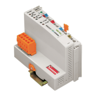
Configuration interface flap opened Fig. 3-1: Fieldbus Coupler 750-306 DeviceNet g030600e The fieldbus Coupler comprises of: • Supply module with Internal system supply module for the system supply as well as power jumper contacts for the field supply via I/O module as- semblies. -
Page 41: Device Supply
Fieldbus Coupler/Controller • 41 Fieldbus Coupler 750-306 3.1.2.2 Device Supply The supply is made via terminal blocks with CAGE CLAMP® connection. The device supply is intended both for the system and the field units. 24V/0V 10nF modules ELECTRONICS FIELDBUS INTERFACE... -
Page 42: Fieldbus Connection
(Open Style Connector). The scope of delivery includes the plug connector 231-305/010-000/050-000 from the WAGO MULTI CONNECTION SYSTEM. The connector has gold plated contacts and has the signal designations printed at its clamping units. -
Page 43: Display Elements
(MS) and the network status (NS). DeviceNet 01 02 OVERFL BUS OFF 24V 0V CONNECT Fig. 3-4: Display elements 750-306 g030602x Color Meaning OVERFL Errors or faults at the fieldbus Coupler. green Fieldbus Coupler is ready for operation. -
Page 44: Configuration Interface
44 • Fieldbus Coupler/Controller Fieldbus Coupler 750-306 3.1.2.5 Configuration Interface The configuration interface used for the communication with WAGO-I/O-CHECK or for firmware transfer is located behind the cover flap. open flap Configuration interface Fig. 3-5: Configuration interface g01xx06e The communication cable (750-920) is connected to the 4-pole header. -
Page 45: Setting The Baud Rate
In the event of a fault, the Coupler changes to the "Stop" condition. The "I/O" LED flashes red. After clearing the fault and cycling power, the Coupler changes to the "Fieldbus start" status and the "I/O" LED lights up green. Fig. 3-8: Operating system 750-306 g012113d WAGO-I/O-SYSTEM 750... -
Page 46: Process Image
46 • Fieldbus Coupler/Controller Fieldbus Coupler 750-306 3.1.4 Process Image After powering up, the Coupler recognizes all I/O modules plugged into the node which supply or wait for data (data width/bit width > 0). In the nodes, analog and digital I/O modules can be mixed. -
Page 47: Data Exchange
The "Predefined Master/Slave Connection Set" confines itself to pure Master/Slave relationships. The DeviceNet fieldbus Coupler 750-306 can only communicate via its as- signed client and it is a so-called "Group 2 Only Server". The Group 2 Only Server communicating is only possible via the Group 2 Only Unconnected Explicit Message Port. -
Page 48: Communication Interfaces
3.1.5.2 Memory Areas The Coupler uses a memory space of 256 words (word 0 ... 255) for the physi- cal input and output data. The division of the memory spaces is identical with all WAGO fieldbus Cou- plers. fieldbus coupler... -
Page 49: Addressing
Fieldbus Coupler/Controller • 49 Fieldbus Coupler 750-306 3.1.5.3 Addressing 3.1.5.3.1 Fieldbus Specific Once the supply voltage is applied, the Assembly Object maps data from the process image. As soon as a connection is established, a DeviceNet-Master (Scanner) can address and access the data by "Class", "Instance" and "Attrib- ute". - Page 50 Input1 (I/O Assembly Instance 4) In this example, the fieldbus node arrangement looks like this: 1) 1 fieldbus coupler DeviceNet (750-306), 2) 1 digital 4-channel input module (i. e. 750-402), 3) 1 digital 4- channel output module (i. e. 750-504), 4) 1 analog 2- channel output module with 2 bytes per channel (i.
-
Page 51: Configuration Software
To enable a connection between the PLC and the fieldbus devices, the inter- face modules have to be configured with the individual station data. To this effect, the scope of delivery of WAGO-I/O-SYSTEM 758 includes the WAGO NETCON software intended for design and configuration, start-up and diagnosis. -
Page 52: Configuration With Static Assembly
1. Starting Software and EDS file load 1. Start the configuration software WAGO NETCON. 2. Load an EDS file for the fieldbus Coupler in WAGO NETCON, i. e. "4.EDS". For this click on "File/ Copy EDS" and choose the EDS-file to load. - Page 53 Fieldbus Coupler/Controller • 53 Fieldbus Coupler 750-306 2. Create a new project 1. Enter the "File" menu and click on menu point "New". 2. Select "DeviceNet" as the fieldbus system and confirm your selection by clicking on the "OK" button.
- Page 54 Fig. 3-15: Insert slave p012501d 3. For the fieldbus Coupler 750-306 click in the left-hand selection window on the corresponding entry to mark it. 4. Take this into the right-hand window by clicking on the "Add" button and confirm by clicking on the "OK" button.
- Page 55 Fieldbus Coupler/Controller • 55 Fieldbus Coupler 750-306 5. Device configuration 1. To configure the device, click on its graphic to mark it, then click on the menu point “Device configuration” in the "Settings" menu. A dialog window opens permitting you to proceed with the desired set- tings.
-
Page 56: Led Display
01 02 OVERFL BUS OFF 24V 0V CONNECT Fig. 3-18: Display elements 750-306 g030602x The module status (MS) and the network status (NS) can be displayed by the top 4 LED’s. They react as described in the table. Module status (MS) -
Page 57: Node Status
Fieldbus Coupler/Controller • 57 Fieldbus Coupler 750-306 3.1.8.1 Node Status Color Meaning red /green The 'I/O' LED indicates the node operation and signals faults occur- / orange ring. The Coupler starts after switching on the supply voltage. The "I/O" LED flashes red. -
Page 58: Blink Code
58 • Fieldbus Coupler/Controller Fieldbus Coupler 750-306 3.1.8.2 Blink Code Detailed fault messages are displayed with the aid of a blink code. A fault is cyclically displayed with up to 3 blink sequences. • The first blink sequence (approx. 10 Hz) starts the fault display. -
Page 59: Supply Voltage Status
Fieldbus Coupler/Controller • 59 Fieldbus Coupler 750-306 Fault code 5: Register communication fault Internal bus fault during register communication with the I/O mod- ule n Fault code 6: Fieldbus specific faults not used Fault code 7: I/O module not supported I/O module not supported at position n * The number of blink pulses (n) indicates the position of the I/O module. -
Page 60: Technical Data
60 • Fieldbus Coupler/Controller Fieldbus Coupler 750-306 3.1.9 Technical Data System data Max. no. of nodes 64 with scanner Max. no. of I/O points ca. 6000 (depends on master) Transmission medium shielded Cu cable, trunk line: AWG 15, 18 (2x 0.82mm +2x1.7mm... -
Page 61: Fieldbus Controller 750-806
Data Exchange ................73 3.2.5.1 Communication Interfaces ............74 3.2.5.2 Memory Areas................74 3.2.5.3 Addressing................77 3.2.6 Programming the PFC with WAGO-I/O-PRO 32 ......81 3.2.6.1 WAGO-I/O-PRO 32 Library Elements........81 3.2.6.2 IEC 61131-3 Program Transfer..........82 3.2.7 Special DeviceNet Features of the Controller.........85 3.2.7.1 Connection via the UCMM port ..........85 3.2.7.2... -
Page 62: Fieldbus Controller
Fieldbus Controller 750-806 3.2.1 Description The programmable fieldbus Controller 750-806 (short: PFC) combines the DeviceNet functions of the fieldbus Coupler 750-306 with that of a program- mable logic control (PLC). The application program is created with WAGO-I/O-PRO 32 in accordance with IEC 61131-3. -
Page 63: Hardware
• Display elements (LEDs) for status display of the operation, the bus com- munication, the operating voltages as well as for fault messages and diag- nosis • Configuration and programming interface and operating mode switch • Electronics for communication with the I/O modules (internal bus) and the fieldbus interface WAGO-I/O-SYSTEM 750 DeviceNet... -
Page 64: Device Supply
Fig. 3-21: Device supply g080601e The integrated internal system supply module generates the necessary voltage to supply the electronics and the connected I/O modules. The fieldbus interface is supplied with electrically isolated voltage from the internal system supply module. WAGO-I/O-SYSTEM 750 DeviceNet... -
Page 65: Fieldbus Connection
3.2.2.3 Fieldbus Connection The scope of delivery includes the plug connector 231-305/010-000/050-000 from the WAGO MULTI CONNECTION SYSTEM. The connector has gold plated contacts and has the signal designations printed at it clamping units. The connection diagram shows the table, the colours resulting in accordance with the DeviceNet specification and are identical to the conductor colours of the DeviceNet cables. -
Page 66: Display Elements
The 'USR' LED can be selected by a user program in a programma- /green / ble fieldbus Controller orange green Status of the operating voltage system green Status of the operating voltage – power jumper contacts WAGO-I/O-SYSTEM 750 DeviceNet... -
Page 67: Configuration And Programming Interface
Feldbus-Koppler/-Controller • 67 Fieldbus Controller 750-806 3.2.2.5 Configuration and Programming Interface The configuration and programming interface is located behind the cover flap. This is used to communicate with WAGO-I/O-CHECK and WAGO-I/O-PRO 32 as well as for firmware transfer. open flap... -
Page 68: Hardware Address (Mac Id)
Note With "GET_STOP_VALUE" (library "System.lib") WAGO-I/O-PRO 32 provides a function which serves to recognize the last cycle prior to a pro- gram stop giving the user the possibility to program the behavior of the Con- troller in case of a STOP. -
Page 69: Setting The Baud Rate
The configuration is only read during the power up sequence. Changing the switch position during operation does not change the configuration of the buscoupler. Turn off and on the power supply for the fieldbus controller to ac- cept the changing. The default setting is Baud rate 125 kB. WAGO-I/O-SYSTEM 750 DeviceNet... -
Page 70: Operating System
WAGO-I/O-PRO 32. The input and output data of the fieldbus and the I/O modules as well as the times are read. Subsequently, the PLC program in the RAM is processed followed by the output data of the fieldbus and the I/O modules in the process image. - Page 71 Fieldbus data, Writing outputs data of I/O modules Operating system functions, updating times operating mode switch STOP is in the top position or Operating mode start command in WAGO-IO- Online/Start Online/Stop Fig. 3-28: Controller operating system g012941d WAGO-I/O-SYSTEM 750 DeviceNet...
-
Page 72: Process Image
The process image for the physical bus module data is identical with that of the WAGO DeviceNet fieldbus Coupler. With the Controller, the data of the PFC variables are filled into the process image, separated according to input and output data. -
Page 73: Data Exchange
Controller. The dynamic assembly can be used to set up Assembly In- stances in which process data from various application objects can be config- ured as required. Further information For information regarding the dynamic Assembly, please refer to chapter 3.2.7.4 "Dynamic Assembly". WAGO-I/O-SYSTEM 750 DeviceNet... -
Page 74: Communication Interfaces
The division of the memory spaces and the access of the PLC functionality (CPU) to the process data is identical with all WAGO fieldbus Controllers. Access is via an application related IEC 61131-3 program and independent on the fieldbus system. - Page 75 CPU for further processing. 4 The variables processed by the CPU via the IEC 61131-3 program are filled in the output memory space and can be read out by the master. WAGO-I/O-SYSTEM 750 DeviceNet...
- Page 76 RAM memory. After an error-free start-up, the PFC cycle starts when the operating mode switch is turned to its upper position or by a start command from WAGO-I/O-PRO 32. WAGO-I/O-SYSTEM 750 DeviceNet...
-
Page 77: Addressing
A process image restructuring may result if a node is changed or extended. In this case, the process data addresses also change in comparison with earlier ones. In the event of adding a module, take the process data of all previous modules into account. WAGO-I/O-SYSTEM 750 DeviceNet... - Page 78 Output process image: Default process data, output image (Assembly Class, Instance 1) Byte low byte channel 1 high byte channel 1 low byte channel 2 high byte channel 2 not used DO04 DO03 DO02 DO01 DO = Digital Output WAGO-I/O-SYSTEM 750 DeviceNet...
- Page 79 Word address (odd numbers) / 2, rounded off 3.2.5.3.4 Address Range for I/O Module Data Data size Address range I/O module data 254.0 254.8 255.0 255.8 0.15 1.15 254.7 254.15 255.7 255.15 Byte Word DWord WAGO-I/O-SYSTEM 750 DeviceNet...
- Page 80 %QD3 (unterer Teil) Data size Flags: %MX11.0 ... 15 %MX12.0 ... 15 Byte %MB22 %MB23 %MB24 %MB25 Word %MW11 %MW12 DWord %MD5 (upper part) %MD6 (lower part) The character 'X' for single bits can be deleted, e.g.%I14.0, %Q6.10, %M11.7 WAGO-I/O-SYSTEM 750 DeviceNet...
-
Page 81: Programming The Pfc With Wago-I/O-Pro 32
This manual, however, does not include a description of how to program with WAGO-I/O-PRO 32. In contrast, the following chapters are to describe the special modules for WAGO-I/O-PRO 32 for you to utilize explicitly for pro- gramming the DeviceNet fieldbus Controller. -
Page 82: Iec 61131-3 Program Transfer
WAGO-I/O-PRO 32 manual (order No.: 759-122 / 000-002). 3.2.6.2.1 Transmission via the Serial Interface Use the WAGO communication cable to produce a physical connection via the serial interface. This is contained in the scope of delivery of the programming tool IEC 61131-3, order No.: 759-332/000-002, or can be purchased as an ac- cessory under order No.: 750-920. - Page 83 Note Transmission via the fieldbus is supported by UCMM. Here, for the down- load of the PFC program, WAGO-I/O-PRO 32 counts as a subscriber. 1. Start the WAGO-I/O-PRO 32 software via ’Start/Programs’ or by double clicking on the WAGO-I/O-PRO-32 symbol on your desk top.
- Page 84 6. Under "Online" click on the "Log-on" menu point to log into the Con- troller. (During online operation, the WAGO-I/O-PRO 32 server is active. The communication parameters cannot be polled.) 7. If there is not a program contained in the Controller, a window appears asking whether or not the program is to be loaded.
-
Page 85: Special Devicenet Features Of The Controller
3.2.7 Special DeviceNet Features of the Controller 3.2.7.1 Connection via the UCMM port In contrast to the fieldbus Coupler 750-306 as a Group 2 Only Server, the De- viceNet Controller supports the dynamic connection via the UCMM port (Un- connected Message Manager Port). -
Page 86: Change Mac Id By Sw
The MAC ID of the Controller can be changed via the network using the soft- ware (e.g. WAGO NETCON, RS NetWorx). For this purpose, the node ad- dress is stored in non-volatile memory. Should the address set at the DIP switch differ from the one set via the network using the software, the I/O LED changes its colour to orange. -
Page 87: Configuration Software
To allow a connection between the PLC and the fieldbus devices, the interface modules have to be configured with the individual station file. To this effect, the scope of the WAGO-I/O-SYSTEM 758 includes the WAGO NETCON software intended for design and configuration, start-up and diagnosis. -
Page 88: Configuration With Static And Dynamic Assembly
2. Load the EDS file "750-806_1.EDS" for the fieldbus Controller in RSNetWorx. For this click on "Tools/ EDS Wizard" and choose the EDS-file to load. Note You can download the EDS file 750-806_1.EDS from the Internet under: www.wago.com 3. Now follow the Wizard instructions. WAGO-I/O-SYSTEM 750 DeviceNet... - Page 89 4 bits input 750-402 4- channel input 4 bits input 750-516 4- channel output 4 bits output 750-516 4- channel output 4 bits output 750-516 4- channel output 4 bits output 750-467 2 channel analog input 4 bytes input WAGO-I/O-SYSTEM 750 DeviceNet...
- Page 90 Controller DIP switch. 3. The RX/TX configuration can be entered in the "Parameters" register. For this purpose, move to the "Groups" dialog box, down along the scroll bar, and select "PLC fieldbus variables". WAGO-I/O-SYSTEM 750 DeviceNet...
- Page 91 12. Then click on the "OK" button to take over the parameters. A window appears indicating that several I/O data will not be mapped. Confirm the question of whether or not you wish to continue by clicking on the "Yes" button. WAGO-I/O-SYSTEM 750 DeviceNet...
- Page 92 1 Word Analog Input Channel 2 I:1.3 1 Byte Status | 1 Byte Digital Inputs I:1.4 1 Word IEC 61131-3 input variable 1 (or PFC output variable 1) I:1.5 1 Word IEC 61131-3 input variable 2 (or PFC output variable 2) WAGO-I/O-SYSTEM 750 DeviceNet...
- Page 93 All outputs are mapped as digital outputs. Mapped Outputs O:1.0 1 Word Reserved for Scanner Module O:1.1 1 Word IEC 61131-3 output variable 1 (or PFC input variable 1) O:1.2 1 Word IEC 61131-3 output variable 2 (or PFC input variable 2) WAGO-I/O-SYSTEM 750 DeviceNet...
- Page 94 1. In the graphical display, click on the symbol of the fieldbus Controller 750- 806 so that the symbol is marked. 2. Then click on the “Class Instance Editor...” menu point in the "Device" menu. A window displaying a warning appears: WAGO-I/O-SYSTEM 750 DeviceNet...
- Page 95 5. Click on the "Execute" button to create the instance for the dynamic as- sembly. If the setting was successful, the fieldbus node will send the instance num- ber = 100 0. If a fault has occurred, you will receive a fault message. WAGO-I/O-SYSTEM 750 DeviceNet...
- Page 96 If the mapping was successful, the fieldbus node sends a “performance” confirmation. If a fault has occurred, you will receive a fault message. In the event of a communication or reply fault, check the DeviceNet con- nection and whether or not the instance was correctly set. WAGO-I/O-SYSTEM 750 DeviceNet...
- Page 97 ID#13 is a pointer for the inputs (Default = 4). This parameter is changed when the inputs are mapped for the master. This is not required due to the fact that the inputs are only read and not written. WAGO-I/O-SYSTEM 750 DeviceNet...
- Page 98 16. Confirm the setting by clicking on the "OK" button. The dialog window is closed. 17. Then switch the supply voltage of the Controller off and on again. Now the fieldbus node is ready for networked communication. WAGO-I/O-SYSTEM 750 DeviceNet...
-
Page 99: Led Display
The device has detected a fault (duplicated MAC ID check error). It is unable to perform any more func- tions in the network. Table 3-4: Fault and status displays: NS WAGO-I/O-SYSTEM 750 DeviceNet... - Page 100 When starting: internal bus is initialized blinks During operation: general internal bus fault Fault message during internal bus reset and internal fault: blinks cyclically orange MAC-ID is changed via SW and is different to the DIP switch setting WAGO-I/O-SYSTEM 750 DeviceNet...
-
Page 101: Blink Code
Fault code 3: Internal bus command fault Busklemme(n) hat (haben) Klemmenbus-Kommando als falsch identifiziert Fault code 4: Internal bus data fault Data fault on internal bus or Internal bus interruption on Coupler n* (n>0) Internal bus interrupted after I/O module n WAGO-I/O-SYSTEM 750 DeviceNet... - Page 102 There are two green LED’s in the Coupler supply section to display the supply voltage. The left LED (A) indicates the 24 V supply for the Coupler. The right hand LED (C) signals the supply to the field side, i.e. the power jumper con- tacts. WAGO-I/O-SYSTEM 750 DeviceNet...
-
Page 103: Technical Data
125 kBaud, 250 kBaud, 500 kBaud BusCoupler connection 5-pole male connector, series 231 (MCS) female connector 231-305/010-000/050-000 is included Programming WAGO-I/O-PRO 32 IEC 61131-3 IL, LD, FBD, ST, FC Standards and approvals E175199, UL508 E198726 Clas I Div2 ABCD T4A (applied for) - Page 104 Dimensions (mm) W x H x L 51 x 65* x 100 (*from top edge of mounting rail) Weight ca. 195 g EMC interference resistance acc. to EN 50082-2 (95) EMC interference transmission acc. to EN 50081-2 (94) WAGO-I/O-SYSTEM 750 DeviceNet...
-
Page 105: O Modules
Fieldbus Controller 750-806 4 I/O modules A detailed description of the fieldbus independence I/O modules of WAGO-I/O-SYSTEM 750 is not part of this manual supplement. Further information Please find the information in the standard manual or in the data sheets. -
Page 106: Devicenet
(1 to 1) by one receiving node, or via a multicast connection (1 to n) by several receiving nodes. Further information The Open DeviceNet Vendor Association (ODVA) provides further docu- ments in the Internet under: http://www.odva.org WAGO-I/O-SYSTEM 750 DeviceNet... -
Page 107: Network Architecture
Baud rate. Note If possible, route the data line separately from all high current carrying ca- bles. Further information For a detailed specification regarding the cable types, please refer to the INTERNET under: http://www.odva.org. WAGO-I/O-SYSTEM 750 DeviceNet... - Page 108 (worst case). 5.2.2 Cabling The connection of a WAGO fieldbus node to the DeviceNet bus cable is made by the supplied 5-pole plug (Multi Connector 231). Fieldbus...
- Page 109 DeviceNet • 109 Network Architecture Note WAGO offers the screen connection system (series 790) for an optimum con- nection between fieldbus cable screening and functional earth. Each DeviceNet node forms the differential voltage U with: U Diff Diff . using the bus levels CAN_High and CAN_Low.
- Page 110 For this purpose, the bus cable has to be looped without interruption. A maximum length of 6 m for a drop line should not be ex- ceeded. The following is a topology example: Power Supply WAGO-I/O-SYSTEM 750 DeviceNet...
- Page 111 5.2.5 Interface Modules In a network, all WAGO DeviceNet fieldbus nodes are delivered to operate as slaves. The master operation is taken over by a central control system, such as PLC, NC or RC.
-
Page 112: Network Communication
(attributes) or resetting a class. • Behaviour: The behaviour defines how a device reacts as a consequence of external events, such as changed process data, or as a consequence of internal events, such as expiring timers. WAGO-I/O-SYSTEM 750 DeviceNet... -
Page 113: Module Characteristics
The data field consists of the service identification and the de- stination address. The format of the explicit messages is defined. Via explicit messages devices can be configured or a dynamic built-up of message con- nections can be made. WAGO-I/O-SYSTEM 750 DeviceNet... -
Page 114: Process Data And Diagnostic Status
The desired process image can be selected by setting the Produced Connection Path and the Consumed Connection Path of the individual I/O connections (Poll, Bit Strobe, Change of State or Change of Value). The architecture of the individual instances of the assembly object is described in the following. WAGO-I/O-SYSTEM 750 DeviceNet... - Page 115 Input 1 (I/O Assembly Instance 7): The entire input data image is transmitted to the master via the corresponding I/O message connection. The data length is equivalent to the number of input data in byte. WAGO-I/O-SYSTEM 750 DeviceNet...
-
Page 116: Configuration / Parametering With The Object Model
ODVA informs about the EDS files of all listed manufacturers. http://www.odva.org EDS and symbol files to configure the I/O modules are available under the order numberr 750-912 on a floppy disk or on the WAGO INTERNET homepage. http://www.wago.com WAGO-I/O-SYSTEM 750... - Page 117 ARRAY Array of ... Note In the following, the object model for the fieldbus Coupler 750-306 and the fieldbus Controller 750-806 are listed. The explicit supplements to the fieldbus Controller 750-806 can be taken from the following chapter. WAGO-I/O-SYSTEM 750...
- Page 118 118 • DeviceNet Configuration / Parametering with the Object Model 5.6.2.1 Object Model for Coupler 750-306 and Controller 750-806 5.6.2.1.1 Classes of Coupler and Controller: Object Class Instance Description Identity 0x01 Device type, vendor ID, serial number etc. Message Router 0x02 Routes explicit messages to the proper destination.
- Page 119 (deleted) 5.6.2.1.5 Assembly Object (0x04): Instance 0: Attribute Used in Access Name Data type Description Value buscoupler rule required Revision UINT Revision of the Identity Object, 0x01 Range 1-65535, class definition upon which the implementation is based. WAGO-I/O-SYSTEM 750 DeviceNet...
- Page 120 Instance 6: Attribute Used in Access Name Data type Description Value buscoupler rule dep. on kind get/set Process Array of process image, collection of all of connected image Byte analog modules process input data modules plus status byte. WAGO-I/O-SYSTEM 750 DeviceNet...
- Page 121 Byte analog modules process input data modules Services: Service Code Service Name Description 0x0E Get_Attribute_Single Used to read a DeviceNet Object attribute value 0x10 Set_Attribute_Single Used to modify a DeviceNet object attribute value WAGO-I/O-SYSTEM 750 DeviceNet...
- Page 122 _length required get/set produ- Array of specifies the application objects which data is ced_conne USINT to be produced by this connection object ction_path required consu- UINT number of Bytes in consu- med_conn med_connection_path attribute ecti- on_path_l WAGO-I/O-SYSTEM 750 DeviceNet...
- Page 123 Array of specifies the application objects that are to med_conn USINT receive the data consumed by this connection object tion_path required producti- USINT defines minimum time between new data on_inhibit production _time WAGO-I/O-SYSTEM 750 DeviceNet...
- Page 124 Array of specifies the application objects that are to med_conn USINT receive the data consumed by this connection object tion_path required producti- USINT defines minimum time between new data on_inhibit production _time WAGO-I/O-SYSTEM 750 DeviceNet...
- Page 125 Used to read a DeviceNet Object attribute value 0x10 Set_Attribute_Single Used to modify a DeviceNet object attribute value 0x05 Reset Restores connection default values. The instances are not available if the connection is in state „non existent“. WAGO-I/O-SYSTEM 750 DeviceNet...
- Page 126 Connec- which will be notified of ack handler objects tion Instance Services: Service Code Service Name Description 0x0E Get_Attribute_Single Used to read a DeviceNet Object attribute value 0x10 Set_Attribute_Single Used to modify a DeviceNet object attribute value WAGO-I/O-SYSTEM 750 DeviceNet...
- Page 127 Non volatile power up value for the polled I/O TORED_PO consumed connection path. The attribute is LL_C_PAT used to hold an enumerator for the assembly path and the class and instance for modules object (discrete input point ...) paths. Write WAGO-I/O-SYSTEM 750 DeviceNet...
- Page 128 0000: All bits are digital nput_mappi 0016: One word is analog remaining bits are digital 0032: Two words are analog remaining bits are digital 0xFFFF: All bits are handled like module type WAGO-I/O-SYSTEM 750 DeviceNet...
- Page 129 UINT Revision of the Identity Object, 0x01 Range 1-65535, class definition upon which the implementation is based. optional UINT maximum number of instances of 0x256 instance an object currently created in this class level of the device WAGO-I/O-SYSTEM 750 DeviceNet...
- Page 130 DOPOBJ_ digital output bit 0:off of connected VALUE 1:on modules Services: Service Code Service Name Description 0x0E Get_Attribute_Single Used to read a DeviceNet Object attribute value 0x10 Set_Attribute_Single Used to modify a DeviceNet object attribute value WAGO-I/O-SYSTEM 750 DeviceNet...
- Page 131 Revision UINT Revision of the Identity Object, Range 1-65535, class definition upon which the implementation is based. optional UINT maximum instance number of an instance object currently created in this class level of device WAGO-I/O-SYSTEM 750 DeviceNet...
- Page 132 Array of Struct The member list is an array of DeviceNet paths Member Data UINT Size of member data Size in Description bits Member Path UINT Size of member path Size in Size bytes Member Path EPATH (**) Required Get/Set Data Array of Byte WAGO-I/O-SYSTEM 750 DeviceNet...
- Page 133 Description for the object instance Ids Instance ID Description Reference to the1. input PLC byte Reference to the 2. input PLC byte … Reference to the 255. input PLC byte WAGO-I/O-SYSTEM 750 DeviceNet...
- Page 134 Used in buscoupler Acces Rule Name DeviceNet data Description of attribute Semantics type of values Optional FB_OUT_VA USINT Output data Actual output data Services: Service code Service name Service description 0x0Eh Get_Attribute_Single Used to read an Object attribute value WAGO-I/O-SYSTEM 750 DeviceNet...
- Page 135 Class 171 (0xAB) Input Fieldbus Variable UDINT PLC input byte 1..128 Max. instance: 128 Starts with 2 bytes offset (the 2nd and 3rd UINT (class166 / instance 2 and 3) = 1st UDINT (class171 / instance 1) etc.) WAGO-I/O-SYSTEM 750 DeviceNet...
- Page 136 Identity Class 1 (0x01) Instance 1: Attribut ID Used in Coupler Access rule Attribute name Data type Description of the attribute Default Value 10 (0x0A) required Get/Set Heartbeat USINT Interval between 2 Heartbe- Interval at messages in seconds WAGO-I/O-SYSTEM 750 DeviceNet...
- Page 137 PFC Output (I/O Assembly Instance 10): Only the PFC output variables are transmitted via the corresponding I/O mes- sage connection. The data length is equivalent to the value in class 100 / in- stance 1 / attribute 101 (BK_FBOUT_ VAR_CNT). WAGO-I/O-SYSTEM 750 DeviceNet...
- Page 138 The data length is equivalent to the value in class 100 / in- stance 1 / attribute 102 (BK_FBINP_PLCONLY_ VAR_CNT). The first PFC transfer byte is defined by the value in class 100 / instance 1 / attribute 103 (BK_FBIN_STARTPLC_VAR_CNT). WAGO-I/O-SYSTEM 750 DeviceNet...
-
Page 139: Application In Explosive Environments
This is backed by law, directives or regulations on a national and international scale. WAGO-I/O- SYSTEM 750 (electrical components) is designed for use in zone 2 explo- sive environments. - Page 140 • IIC – Hydrogen Minimal Ignition Energy of Representative Types of Gases Explosion Group Gases Methane Propane Ethylene Hydrogen Ignition Energy (µJ) Hydrogen being commonly encountered in chemical plants, frequently the explosion group IIC is requested for maximum safety. WAGO-I/O-SYSTEM 750 DeviceNet...
- Page 141 Zone 0 Explosive environment by gas, fumes or mist Zone 1 Explosive environment by gas, fumes or mist Zone 2 Explosive environment by gas, fumes or mist Zone 20 Explosive environment by dust Zone 21 Explosive environment by dust Zone 22 Explosive environment by dust WAGO-I/O-SYSTEM 750 DeviceNet...
- Page 142 Temperature Classes Total 26.6 % 42.8 % 25.5 % 94.9 % 4.9 % 0.2 % Explosion Group Total 80.2 % 18.1 % 0.7 % Number of classified materials WAGO-I/O-SYSTEM 750 DeviceNet...
- Page 143 • AC – spark generating, contacts protected by seals (function modules with relays / without switches) • L – limited energy (function modules with switch) Further information For more detailed information please refer to the national and/or international standards, directives and regulations! WAGO-I/O-SYSTEM 750 DeviceNet...
-
Page 144: Classifications Meeting The Nec 500
Class I (gases and fumes): Group A (Acetylene) Group B (Hydrogen) Group C (Ethylene) Group D (Methane) Class II (dust): Group E (Metal dust) Group F (Coal dust) Group G (Flour, starch and cereal dust) Class III (fibers): No sub-groups WAGO-I/O-SYSTEM 750 DeviceNet... - Page 145 >165 °C to 180 °C 160 °C >160 °C to 165 °C 135 °C >135 °C to 160 °C 120 °C >120 °C to 135 °C 100 °C >100 °C to 120 °C 85 °C > 85 °C to 100 °C WAGO-I/O-SYSTEM 750 DeviceNet...
-
Page 146: Identification
2DI 24V DC 3.0ms Hansastr. 27 D-32423 Minden 0.08-2.5mm PATENTS PENDING II 3 G KEMA 01ATEX1024 X EEx nA II T4 Fig. 6-1: Example for lateral labeling of bus modules (750-400, 2 channel digital input module 24 V DC) g01xx03e WAGO-I/O-SYSTEM 750 DeviceNet... - Page 147 2DI 24V DC 3.0ms Hansastr. 27 D-32423 Minden 0.08-2.5mm PATENTS PENDING II 3 G KEMA 01ATEX1024 X EEx nA II T4 Fig. 6-2: Example for lateral labeling of bus modules (750-400, 2 channel digital input module 24 V DC) g01xx04e WAGO-I/O-SYSTEM 750 DeviceNet...
-
Page 148: Installation Regulations
C22.1 Canadian Electrical Code Danger For the use of WAGO-I/O SYSTEM 750 (electrical operating means) with Ex approval the observance of the following points is mandatory: • The electrical operating means are exclusively suitable for applications in explosion endangered areas (Europe Group II, Zone 2 or America: Class I, Division 2, Group A, B, C, D) or in non-explosion endangered areas! •... - Page 149 Application in Explosive Environments • 149 Installation Regulations Further Information Proof of certification is available on request. Also take note of the information given on the module technical information sheet. WAGO-I/O-SYSTEM 750 DeviceNet...
-
Page 150: Glossary
Device providing services within a client/server sys- Server tem. The service is requested by the Client. A portion of a network that shares the same network Subnet address as the other portions. These subnets are dis- tinguished through the subnet mask. WAGO-I/O-SYSTEM 750 DeviceNet... -
Page 151: Literature List
Konrad Etschberger 2., völlig überarbeitete Auflage 2000 Carl Hanser Verlag München Wien ISBN 3-4446-19431-2 Further information on web pages: The ODVA provides further documentation on DeviceNet. www.odva.org CAN in Automation (CiA) provides further documentation on CAN. can-cia.de WAGO-I/O-SYSTEM 750 DeviceNet... -
Page 152: Index
Times ................... 70 I/O modules ................105 Address range ................ 79 unlocking lug ................17 IEC 61131-3 ................103 Internal bus..............63, 70, 101 Variables..................67 Light diodes................43, 66 locking disc ................. 17 WAGO-I/O-PRO 32 ............68, 83, 87 Loop .................... 70 WAGO-I/O-SYSTEM 750 DeviceNet...
Need help?
Do you have a question about the 750-306 and is the answer not in the manual?
Questions and answers