
Related Manuals for WAGO DeviceNet 750-306


Summary of Contents for WAGO DeviceNet 750-306
- Page 1 WAGO-I/O-SYSTEM 750 Manual 750-306 DeviceNet Fieldbus Coupler 125 Kbaud ... 500 Kbaud; digital and analog signals Version 2.0.0...
- Page 2 WAGO-I/O-SYSTEM 750 750-306 DeviceNet Fieldbus Coupler © 2015 by WAGO Kontakttechnik GmbH & Co. KG All rights reserved. WAGO Kontakttechnik GmbH & Co. KG Hansastraße 27 D-32423 Minden Phone: +49 (0) 571/8 87 – 0 Fax: +49 (0) 571/8 87 – 1 69 E-Mail: info@wago.com...
-
Page 3: Table Of Contents
2.1.1 Subject to Changes ................11 2.1.2 Personnel Qualifications ..............11 2.1.3 Use of the WAGO-I/O-SYSTEM 750 in Compliance with Underlying Provisions ................... 11 2.1.4 Technical Condition of Specified Devices ......... 12 Safety Advice (Precautions) ..............13 System Description..................15 Manufacturing Number ................ - Page 4 Overall Configuration ................52 Mounting onto Carrier Rail ..............54 5.3.1 Carrier Rail Properties ................ 54 5.3.2 WAGO DIN Rail ................55 Spacing ....................55 Mounting Sequence ................. 56 Inserting and Removing Devices ............57 5.6.1 Inserting the Fieldbus Coupler/Controller .......... 58 5.6.2...
- Page 5 WAGO-I/O-SYSTEM 750 Table of Contents 750-306 DeviceNet Fieldbus Coupler Diagnostics ....................74 LED Signaling ..................74 9.1.1 Evaluating the Fieldbus Status ............75 9.1.2 Evaluating Node Status – I/O LED (Blink Code Table) ....76 9.1.3 Evaluating Power Supply Status ............83 Fieldbus Communication ................
- Page 6 Table of Contents WAGO-I/O-SYSTEM 750 750-306 DeviceNet Fieldbus Coupler Use in Hazardous Environments ............145 12.1 Marking Configuration Examples ............146 12.1.1 Marking for Europe According to ATEX and IEC-Ex ....146 12.1.2 Marking for America According to NEC 500 ........151 12.2...
-
Page 7: Notes About This Documentation
Manual by third parties that violate pertinent copyright provisions is prohibited. Reproduction, translation, electronic and phototechnical filing/archiving (e.g., photocopying) as well as any amendments require the written consent of WAGO Kontakttechnik GmbH & Co. KG, Minden, Germany. Non-observance will involve the right to assert damage claims. Manual... -
Page 8: Symbols
Notes about this Documentation WAGO-I/O-SYSTEM 750 750-306 DeviceNet Fieldbus Coupler Symbols Personal Injury! Indicates a high-risk, imminently hazardous situation which, if not avoided, will result in death or serious injury. Personal Injury Caused by Electric Current! Indicates a high-risk, imminently hazardous situation which, if not avoided, will result in death or serious injury. - Page 9 WAGO-I/O-SYSTEM 750 Notes about this Documentation 750-306 DeviceNet Fieldbus Coupler Additional Information: Refers to additional information which is not an integral part of this documentation (e.g., the Internet). Manual Version 2.0.0...
-
Page 10: Number Notation
Font Conventions Table 2: Font Conventions Font Type Indicates italic Names of paths and data files are marked in italic-type. e.g.: C:\Program Files\WAGO Software Menu items are marked in bold letters. Menu e.g.: Save > A greater-than sign between two names means the selection of a menu item from a menu. -
Page 11: Important Notes
2.1.1 Subject to Changes WAGO Kontakttechnik GmbH & Co. KG reserves the right to provide for any alterations or modifications that serve to increase the efficiency of technical progress. WAGO Kontakttechnik GmbH & Co. KG owns all rights arising from the granting of patents or from the legal protection of utility patents. -
Page 12: Technical Condition Of Specified Devices
WAGO-I/O-SYSTEM 750 750-306 DeviceNet Fieldbus Coupler Appropriate housing (per 94/9/EG) is required when operating the WAGO-I/O- SYSTEM 750 in hazardous environments. Please note that a prototype test certificate must be obtained that confirms the correct installation of the system in a housing or switch cabinet. -
Page 13: Safety Advice (Precautions)
Install the device only in appropriate housings, cabinets or in electrical operation rooms! The WAGO-I/O-SYSTEM 750 and its components are an open system. As such, install the system and its components exclusively in appropriate housings, cabinets or in electrical operation rooms. Allow access to such equipment and fixtures to authorized, qualified staff only by means of specific keys or tools. - Page 14 Important Notes WAGO-I/O-SYSTEM 750 750-306 DeviceNet Fieldbus Coupler Do not use any contact spray! Do not use any contact spray. The spray may impair contact area functionality in connection with contamination. Do not reverse the polarity of connection lines! Avoid reverse polarity of data and power supply lines, as this may damage the devices involved.
-
Page 15: System Description
The fieldbus coupler/controller exchanges process data with the respective control via the respective fieldbus. The programmable fieldbus controllers (PFC) allow implementation of additional PLC functions. WAGO-I/O-PRO is used to program the fieldbus controllers according to IEC 61131-3. I/O modules for diverse digital and analog I/O signals as well as special functions can be connected to the fieldbus coupler/controller. -
Page 16: Manufacturing Number
System Description WAGO-I/O-SYSTEM 750 750-306 DeviceNet Fieldbus Coupler Manufacturing Number The serial number indicates the delivery status directly after production. This number is part of the labeling on the side of each component. In addition, the serial number is printed on the cover cap of the configuration and programming interface of the fieldbus coupler/controller, so that it can also be read when installed. -
Page 17: Component Update
WAGO-I/O-SYSTEM 750 System Description 750-306 DeviceNet Fieldbus Coupler Component Update For the case of an update of one component, the lateral marking on each component contains a prepared matrix. This matrix makes columns available for altogether three updates to the entry of the current update data, like production order number (NO;... -
Page 18: Assembly Guidelines/Standards
System Description WAGO-I/O-SYSTEM 750 750-306 DeviceNet Fieldbus Coupler Assembly Guidelines/Standards • DIN 60204 Electrical equipping of machines • DIN EN 50178 Equipping of high-voltage systems with electronic components (replacement for VDE 0160) • EN 60439 Low-voltage switchgear and controlgear assemblies Manual Version 2.0.0... -
Page 19: Power Supply
WAGO-I/O-SYSTEM 750 System Description 750-306 DeviceNet Fieldbus Coupler Power Supply 3.5.1 Isolation Within the fieldbus node, there are three electrically isolated potentials: • Electrically isolated fieldbus interface via transformer • Electronics of the fieldbus couplers/controllers and the I/O modules (internal bus) •... -
Page 20: System Supply
System Supply 3.5.2.1 Connection The WAGO-I/O-SYSTEM 750 requires a 24 V direct current system supply. The power supply is provided via the fieldbus coupler/controller and, if necessary, in addition via internal system supply modules 750-613. The power supply is reverse voltage protected. -
Page 21: Dimensioning
WAGO-I/O-SYSTEM 750 System Description 750-306 DeviceNet Fieldbus Coupler Figure 5: System Voltage for Standard Couplers/Controllers and Extended ECO Couplers Only reset the system simultaneously for all supply modules! Reset the system by simultaneously switching the system supply at all supply modules (fieldbus coupler/controller and potential supply module with bus power supply) off and on again. - Page 22 Consequently, an internal system supply module (750-613), e. g. in the middle of the node, should be added. Recommendation ® Utilize the smartDESIGNER feature WAGO ProServe software to configure fieldbus node assembly. You can test the configuration via the integrated plausibility check.
- Page 23 WAGO-I/O-SYSTEM 750 System Description 750-306 DeviceNet Fieldbus Coupler Fieldbus coupler or controller = Sum of all the internal current consumption of the connected (5 V) total I/O modules + internal current consumption of the fieldbus coupler/controller Internal system supply module...
-
Page 24: Field Supply
System Description WAGO-I/O-SYSTEM 750 750-306 DeviceNet Fieldbus Coupler 3.5.3 Field Supply 3.5.3.1 Connection Sensors and actuators can be directly connected to the relevant channel of the I/O module in 1, 2, 3 or 4 conductor connection technology. The I/O module supplies power to the sensors and actuators. -
Page 25: Table 5: Legend For Figure "Field Supply For Standard Couplers/Controllers And Extended Eco Couplers
WAGO-I/O-SYSTEM 750 System Description 750-306 DeviceNet Fieldbus Coupler Table 5: Legend for Figure “Field Supply for Standard Couplers/Controllers and Extended ECO Couplers” Field supply 24 V (-15 % / +20 %) Optional ground potential Power jumper contacts Potential distribution to adjacent I/O modules The field-side power supply is automatically derived from the power jumper contacts when snapping an I/O module. -
Page 26: Fusing
System Description WAGO-I/O-SYSTEM 750 750-306 DeviceNet Fieldbus Coupler 3.5.3.2 Fusing Internal fusing of the field supply is possible for various field voltages via an appropriate power supply module. Table 6: Power Supply Modules Order No. Field Voltage 750-601 24 V DC, Supply/Fuse... -
Page 27: Figure 8: Removing The Fuse Carrier
WAGO-I/O-SYSTEM 750 System Description 750-306 DeviceNet Fieldbus Coupler In order to insert or change a fuse, or to switch off the voltage in succeeding I/O modules, the fuse holder may be pulled out. In order to do this, use a screwdriver for example, to reach into one of the slits (one on both sides) and pull out the holder. -
Page 28: Figure 11: Fuse Modules For Automotive Fuses, Series 282
WAGO-I/O-SYSTEM 750 750-306 DeviceNet Fieldbus Coupler Alternatively, fusing can be done externally. The fuse modules of the WAGO series 281 and 282 are suitable for this purpose. Figure 11: Fuse Modules for Automotive Fuses, Series 282 Figure 12: Fuse Modules for Automotive Fuses, Series 2006... -
Page 29: Supplementary Power Supply Regulations
Fieldbus Coupler 3.5.4 Supplementary Power Supply Regulations The WAGO-I/O-SYSTEM 750 can also be used in shipbuilding or offshore and onshore areas of work (e. g. working platforms, loading plants). This is demonstrated by complying with the standards of influential classification companies such as Germanischer Lloyd and Lloyds Register. -
Page 30: Supply Example
System Description WAGO-I/O-SYSTEM 750 750-306 DeviceNet Fieldbus Coupler 3.5.5 Supply Example Suppl Sggggggggggggggggg The system supply and the field supply shall be separated! You should separate the system supply and the field supply in order to ensure bus operation in the event of a short-circuit on the actuator side. -
Page 31: Table 8: Legend For Figure "Supply Example For Fieldbus Coupler/Controller
WAGO-I/O-SYSTEM 750 System Description 750-306 DeviceNet Fieldbus Coupler Table 8: Legend for Figure “Supply Example for Fieldbus Coupler/Controller” Pos. Description Power Supply on coupler via external Supply Module Power Supply with optional ground Internal System Supply Module Separation module recommended... -
Page 32: Power Supply Unit
Fieldbus Coupler 3.5.6 Power Supply Unit The WAGO-I/O-SYSTEM 750 requires a 24 VDC voltage (system supply). Recommendation A stable power supply cannot always be assumed everywhere. Therefore, you should use regulated power supplies to ensure the quality of the supply voltage (see also table “WAGO power supply units”). -
Page 33: Grounding
The separate grounding of the carrier rail can be easily set up with the aid of the WAGO ground wire terminals. Table 10: WAGO Ground Wire Terminals Order No. Description 283-609 1-conductor ground (earth) terminal block make an automatic contact to the carrier rail;... -
Page 34: Grounding Function
System Description WAGO-I/O-SYSTEM 750 750-306 DeviceNet Fieldbus Coupler 3.6.2 Grounding Function The grounding function increases the resistance against electro-magnetic interferences. Some components in the I/O system have a carrier rail contact that dissipates electro-magnetic interferences to the carrier rail. Figure 17: Carrier Rail Contact (Example) -
Page 35: Shielding
Higher shielding performance is achieved via low-impedance connection between shield and ground. For this purpose, connect the shield over a large surface area, e.g., WAGO shield connecting system. This is especially recommended for large- scale systems where equalizing current or high impulse-type currents caused by atmospheric discharge may occur. -
Page 36: Signal Lines
3.7.4 WAGO Shield Connecting System The WAGO shield connecting system consists of shield clamping saddles, busbars and various mounting carriers. These components can be used to achieve many different configurations. -
Page 37: Device Description
This fieldbus coupler can be used for applications in mechanical and systems engineering, as well as in the processing industry. The fieldbus connection is made via 231 series 5-pin plug connector of the WAGO MULTI CONNECTION SYSTEM (MCS). The DIP switch can be used to specify baud rate and station address of the fieldbus coupler. -
Page 38: View
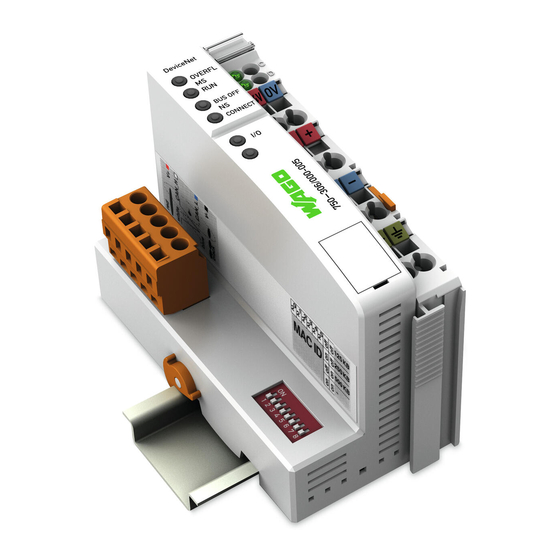
Device Description WAGO-I/O-SYSTEM 750 750-306 DeviceNet Fieldbus Coupler View The view below shows the three parts of the device: • The left side shows the fieldbus connection and a DIP switch to set both the node ID and baud rate. -
Page 39: Table 11: Legend For Figure "View Devicenet Tm Fieldbus Coupler
WAGO-I/O-SYSTEM 750 Device Description 750-306 DeviceNet Fieldbus Coupler Table 11: Legend for Figure “View DeviceNet Fieldbus Coupler” Desig- Pos. Meaning Details see Section nation OVERFL, RUN, “Device Description” > Status LEDs Fieldbus BUS OFF, “Display Elements” CONNECT Group marking carrier (retractable) with... -
Page 40: Connectors
Device Description WAGO-I/O-SYSTEM 750 750-306 DeviceNet Fieldbus Coupler Connectors 4.2.1 Device Supply ® The device is powered via terminal blocks with CAGE CLAMP connections. The device supply generates the necessary voltage to power the electronics of the device and the internal electronics of the connected I/O modules. -
Page 41: Fieldbus Connection
WAGO-I/O-SYSTEM 750 Device Description 750-306 DeviceNet Fieldbus Coupler 4.2.2 Fieldbus Connection The fieldbus connection for DeviceNet is made via Series 231 5-pin plug connector from the MULTI CONNECTION SYSTEM (MCS). A connector (OpenStyle) is the counterpart. The 231-305/010-000/050-000 connector is included. -
Page 42: Display Elements
Device Description WAGO-I/O-SYSTEM 750 750-306 DeviceNet Fieldbus Coupler Display Elements The operating condition of the fieldbus coupler or the node is displayed with the help of illuminated indicators in the form of light-emitting diodes (LEDs). The LED information is routed to the top of the case by light guides. In some cases, the LEDs are multi-colored (red, green or orange). -
Page 43: Operating Elements
4.4.1 Service Interface The service interface is located behind the flap. It is used for the communication with the WAGO-I/O-CHECK and for downloading the firmware updates. Figure 25: Service Interface (Closed and Opened Flap) Table 16: Legend for Figure “Service Interface (Closed and Opened Flap)”... -
Page 44: Dip Switch
Device Description WAGO-I/O-SYSTEM 750 750-306 DeviceNet Fieldbus Coupler 4.4.2 DIP Switch Figure 26: DIP Switch The DIP switch is used to set the baud rate of the fieldbus coupler and to set the DeviceNet station address (relating to DeviceNet , also called “MAC ID”). -
Page 45: Station Address
WAGO-I/O-SYSTEM 750 Device Description 750-306 DeviceNet Fieldbus Coupler 4.4.2.2 Station address The station address is set using slide switches 1 to 6. The binary significance of the individual slide switches increases in the direction of the slide switch numbers. Slide switch 1 is used to set the lowest bit with a... -
Page 46: Technical Data
Device Description WAGO-I/O-SYSTEM 750 750-306 DeviceNet Fieldbus Coupler Technical Data 4.5.1 Device Data Table 18: Technical Data, Device Data Width 51 mm Height (from upper-edge of DIN- 65 mm 35 rail) Depth 100 mm Weight approx. 195 g Degree of protection IP20 4.5.2... -
Page 47: Supply
WAGO-I/O-SYSTEM 750 Device Description 750-306 DeviceNet Fieldbus Coupler 4.5.4 Supply Table 21: Technical Data, Power Supply Voltage via power jumper contacts 24 VDC (-15% ... +20%) Current via power jumper contacts 10 ADC max. Power supply efficiency at nominal typ. -
Page 48: Climatic Environmental Conditions
Device Description WAGO-I/O-SYSTEM 750 750-306 DeviceNet Fieldbus Coupler 4.5.7 Climatic Environmental Conditions Table 26: Technical Data – Climatic Environmental Conditions Operating temperature range 0 °C … 55 °C −20 °C … +60 °C Operating temperature range for components with extended temperature range (750-xxx/025-xxx) −25 °C …... -
Page 49: Approvals
Fieldbus Coupler Approvals More information about approvals. Detailed references to the approvals are listed in the document “Overview Approvals WAGO-I/O-SYSTEM 750”, which you can find via the internet under: www.wago.com > SERVICES > DOWNLOADS > Additional documentation and information on automation products > WAGO-I/O-SYSTEM 750 >... - Page 50 Device Description WAGO-I/O-SYSTEM 750 750-306 DeviceNet Fieldbus Coupler The following ship approvals have been granted to 750-306 fieldbus coupler/controller: ABS (American Bureau of Shipping) Federal Maritime and Hydrographic Agency BV (Bureau Veritas) DNV (Det Norske Veritas) Class B GL (Germanischer Lloyd) Cat.
-
Page 51: Standards And Guidelines
WAGO-I/O-SYSTEM 750 Device Description 750-306 DeviceNet Fieldbus Coupler Standards and Guidelines 750-306 meets the following requirements on emission and immunity of interference: EMC CE-Immunity to interference acc. to EN 61000-6-2 EMC CE-Emission of interference acc. to EN 61000-6-3 EMC marine applications-Immunity to interference acc. -
Page 52: Mounting
Use an end stop in the case of vertical mounting! In the case of vertical assembly, an end stop has to be mounted as an additional safeguard against slipping. WAGO order no. 249-116 End stop for DIN 35 rail, 6 mm wide WAGO order no. 249-117... - Page 53 WAGO-I/O-SYSTEM 750 Mounting 750-306 DeviceNet Fieldbus Coupler Increase the total length using a coupler module for internal data bus extension! You can increase the total length of a fieldbus node by using a 750-628 I/O Module (coupler module for internal data bus extension). For such a configuration, attach a 750-627 I/O Module (end module for internal data bus extension) after the last I/O module of a module assembly.
-
Page 54: Mounting Onto Carrier Rail
WAGO Kontakttechnik GmbH & Co. KG supplies standardized carrier rails that are optimal for use with the I/O system. If other carrier rails are used, then a technical inspection and approval of the rail by WAGO Kontakttechnik GmbH & Co. KG should take place. -
Page 55: Wago Din Rail
WAGO-I/O-SYSTEM 750 Mounting 750-306 DeviceNet Fieldbus Coupler 5.3.2 WAGO DIN Rail WAGO carrier rails meet the electrical and mechanical requirements shown in the table below. Table 28: WAGO DIN Rail Order number Description 210-113 /-112 35 x 7.5; 1 mm; steel yellow chromated; slotted/unslotted 210-114 /-197 35 x 15;... -
Page 56: Mounting Sequence
Don't forget the bus end module! Always plug a bus end module 750-600 onto the end of the fieldbus node! You must always use a bus end module at all fieldbus nodes with WAGO-I/O- SYSTEM 750 fieldbus couplers/controllers to guarantee proper data transfer. -
Page 57: Inserting And Removing Devices
WAGO-I/O-SYSTEM 750 Mounting 750-306 DeviceNet Fieldbus Coupler Inserting and Removing Devices Perform work on devices only if they are de-energized! Working on energized devices can damage them. Therefore, turn off the power supply before working on the devices. Manual Version 2.0.0... -
Page 58: Inserting The Fieldbus Coupler/Controller
Mounting WAGO-I/O-SYSTEM 750 750-306 DeviceNet Fieldbus Coupler 5.6.1 Inserting the Fieldbus Coupler/Controller When replacing the fieldbus coupler/controller for an already available fieldbus coupler/controller, position the new fieldbus coupler/controller so that the tongue and groove joints to the subsequent I/O module are engaged. -
Page 59: Inserting The I/O Module
WAGO-I/O-SYSTEM 750 Mounting 750-306 DeviceNet Fieldbus Coupler 5.6.3 Inserting the I/O Module Position the I/O module so that the tongue and groove joints to the fieldbus coupler/controller or to the previous or possibly subsequent I/O module are engaged. Figure 31: Insert I/O Module (Example) Press the I/O module into the assembly until the I/O module snaps into the carrier rail. -
Page 60: Removing The I/O Module
Mounting WAGO-I/O-SYSTEM 750 750-306 DeviceNet Fieldbus Coupler 5.6.4 Removing the I/O Module Remove the I/O module from the assembly by pulling the release tab. Figure 33: Removing the I/O Module (Example) Electrical connections for data or power jumper contacts are disconnected when removing the I/O module. -
Page 61: Connect Devices
WAGO-I/O-SYSTEM 750 Connect Devices 750-306 DeviceNet Fieldbus Coupler Connect Devices Data Contacts/Internal Bus Communication between the fieldbus coupler/controller and the I/O modules as well as the system supply of the I/O modules is carried out via the internal bus. It is comprised of 6 data contacts, which are available as self-cleaning gold spring contacts. -
Page 62: Power Contacts/Field Supply
Figure 35: Example for the Arrangement of Power Contacts Field bus node configuration and test via smartDESIGNER ® With the WAGO ProServe Software smartDESIGNER, you can configure the structure of a fieldbus node. You can test the configuration via the integrated accuracy check. -
Page 63: Connecting A Conductor To The Cage Clamp
Only one conductor may be connected to each CAGE CLAMP Do not connect more than one conductor at one single connection! If more than one conductor must be routed to one connection, these must be connected in an up-circuit wiring assembly, for example using WAGO feed- through terminals. Exception: If it is unavoidable to jointly connect 2 conductors, then you must use a ferrule to join the wires together. -
Page 64: Function Description
Function Description WAGO-I/O-SYSTEM 750 750-306 DeviceNet Fieldbus Coupler Function Description Operating System After master configuration and electrical installation of the fieldbus station, the system is operative. The coupler begins running up after switching on the power supply or after a reset. -
Page 65: Process Data Architecture
WAGO-I/O-SYSTEM 750 Function Description 750-306 DeviceNet Fieldbus Coupler Process Data Architecture 7.2.1 Basic Setup After switching on the fieldbus coupler, it identifies all I/O modules of the node that send or expect to receive data (data/bit width > 0). Any number of analog input/output modules and digital input/output modules can be arranged within a node. -
Page 66: Data Exchange
Function Description WAGO-I/O-SYSTEM 750 750-306 DeviceNet Fieldbus Coupler Data Exchange Objects are used for exchange of process data for the DeviceNet fieldbus coupler. For access from the network to the individual objects, connections between the required subscribes must first be established and connection objects set up or activated. -
Page 67: Communication Interfaces
WAGO-I/O-SYSTEM 750 Function Description 750-306 DeviceNet Fieldbus Coupler 7.3.1 Communication Interfaces Basically, the fieldbus coupler has two interfaces for exchanging data: • Interface to the fieldbus (fieldbus master) • Interface to the I/O modules. Data is exchanged between the fieldbus master and the I/O modules. -
Page 68: Addressing
Function Description WAGO-I/O-SYSTEM 750 750-306 DeviceNet Fieldbus Coupler 7.3.3 Addressing 7.3.3.1 Fieldbus-Specific Addressing After turning on the power supply, the assembly object combines data from the process image. As soon as a connection is established, a DeviceNet master (scanner) can address the data with “class”, “instance” and “Attribute” and then access it or read and/or write via I/O connections. -
Page 69: Table 29: Input Process Image
WAGO-I/O-SYSTEM 750 Function Description 750-306 DeviceNet Fieldbus Coupler Take into account the process data of previous I/O modules in case of an expansion! If a node is changed or expanded, this may result in a new process image structure. In this case, the process data addresses also change. In case of an expansion, the process data of all previous I/O modules has to be taken into account. -
Page 70: Table 30: Output Process Image
Function Description WAGO-I/O-SYSTEM 750 750-306 DeviceNet Fieldbus Coupler Output process image: Standard process data, output image (Assembly Class, Instance 1) Table 30: Output Process Image Bit 7 Bit 6 Bit 5 Bit 4 Bit 3 Bit 2 Bit 1 Bit 0... -
Page 71: Commissioning
Commissioning 750-306 DeviceNet Fieldbus Coupler Commissioning This section shows a step-by-step procedure for starting up exemplarily a WAGO fieldbus node. Exemplary Example! This description is exemplary and is limited here to the execution of a local start- up of one individual DeviceNet fieldbus node with a non-interlaced computer running Windows. -
Page 72: Connecting Client Pc And Fieldbus Nodes
Commissioning WAGO-I/O-SYSTEM 750 750-306 DeviceNet Fieldbus Coupler Connecting Client PC and Fieldbus Nodes 1. Mount the fieldbus node to the carrier rail. Observe the installation instructions described in “Mounting” section. 2. Use a fieldbus cable to connect the DeviceNet fieldbus node to the DeviceNet fieldbus card in your PC. -
Page 73: Setting The Devicenet ™ Station Address And Baud Rate
Configuring static assemblies is described in a separate document. Please note Application Note A100103! Configuring static assemblies is described in Application Note A100103. The application note is available for download at the WAGO website http://www.wago.com. Additional Information ESD files for the fieldbus coupler are available in the Download area on the website http://www.wago.com. -
Page 74: Devicenet Tm Fieldbus Coupler
Diagnostics WAGO-I/O-SYSTEM 750 750-306 DeviceNet Fieldbus Coupler Diagnostics LED Signaling For on-site diagnostics, the fieldbus coupler has several LEDs that indicate the operational status of the fieldbus coupler or the entire node (see following figure). Figure 41: Display Elements The diagnostics displays and their significance are explained in detail in the following section. -
Page 75: Evaluating The Fieldbus Status
WAGO-I/O-SYSTEM 750 Diagnostics 750-306 DeviceNet Fieldbus Coupler 9.1.1 Evaluating the Fieldbus Status Communication via the fieldbus is by the top LED group. The two “MS” (“Module Status”) and “NS” (“Network Status”) LEDs are used for the status of the system and fieldbus connections. -
Page 76: Evaluating Node Status - I/O Led (Blink Code Table)
Diagnostics WAGO-I/O-SYSTEM 750 750-306 DeviceNet Fieldbus Coupler 9.1.2 Evaluating Node Status – I/O LED (Blink Code Table) The communication status between fieldbus coupler/controller and the I/O modules is indicated by the I/O LED. Table 34: Node Status Diagnostics – Solution in Event of Error... -
Page 77: Figure 42: Node Status - I/O Led Signaling
WAGO-I/O-SYSTEM 750 Diagnostics 750-306 DeviceNet Fieldbus Coupler Figure 42: Node Status – I/O LED Signaling Figure 43: Error Message Coding Example of a module error: • The I/O LED starts the error display with the first flashing sequence (approx. 10 Hz). -
Page 78: Table 35: Blink Code- Table For The I/O Led Signaling, Error Code 1
Diagnostics WAGO-I/O-SYSTEM 750 750-306 DeviceNet Fieldbus Coupler • After the second break, the third flashing sequence starts (approx. 1 Hz): The I/O LED blinks twelve times. Error argument 12 means that the internal data bus is interrupted behind the twelfth I/O module. -
Page 79: Table 36: Blink Code Table For The I/O Led Signaling, Error Code 2
WAGO-I/O-SYSTEM 750 Diagnostics 750-306 DeviceNet Fieldbus Coupler Table 35: Blink code- table for the I/O LED signaling, error code 1 Error code 1: “Hardware and configuration error” Error Error Description Solution Argument The I/O module configuration after AUTORESET differs from the 1. -
Page 80: Table 37: Blink Code Table For The I/O Led Signaling, Error Code 3
Diagnostics WAGO-I/O-SYSTEM 750 750-306 DeviceNet Fieldbus Coupler Table 37: Blink Code Table for the I/O LED Signaling, Error Code 3 Error code 3: “Protocol error, internal bus” Error Error Description Solution Argument - Are passive power supply modules (750-613) located in the node? - 1. -
Page 81: Table 38: Blink Code Table For The I/O Led Signaling, Error Code 4
WAGO-I/O-SYSTEM 750 Diagnostics 750-306 DeviceNet Fieldbus Coupler Table 38: Blink Code Table for the I/O LED Signaling, Error Code 4 Error code 4: “Physical error, internal bus” Error Error Description Solution Argument 1. Turn off the power supply to the node. -
Page 82: Table 40: Blink Ccode Table For The I/O Led Signaling, Error Code 6
Diagnostics WAGO-I/O-SYSTEM 750 750-306 DeviceNet Fieldbus Coupler Table 40: Blink Ccode Table for the I/O LED Signaling, Error Code 6 … 8 Error code 6 … 8: -not used- Error Error Description Solution Argument Not used Table 41: Blink Code Table for the I/O LED Signaling, Error Code 9 Error code 9: “CPU Trap error”... -
Page 83: Evaluating Power Supply Status
WAGO-I/O-SYSTEM 750 Diagnostics 750-306 DeviceNet Fieldbus Coupler Table 43: Blink Code Table for the I/O LED Signaling, Error Code 11 Error code 11: “Error in I/O modules with gateway/mailbox functionality” Error Error Description Remedy Argument Too many I/O modules with gateway 1. -
Page 84: Fieldbus Communication
Fieldbus Communication WAGO-I/O-SYSTEM 750 750-306 DeviceNet Fieldbus Coupler Fieldbus Communication 10.1 DeviceNet DeviceNet is a network concept on the device level based on the serial bus system “Controller Area Network” (CAN). It is particularly characterized by easy addition and removal of devices during operation. The range of devices spans from simple light barriers to complex engine control units. -
Page 85: Network Structure
WAGO-I/O-SYSTEM 750 Fieldbus Communication 750-306 DeviceNet Fieldbus Coupler Additional Information The “Open DeviceNet Vendor Association” (ODVA) makes more information available on the Internet at: http://www.odva.org. Additional Information “CAN in Automation” (CiA) makes documentation about CAN networks available on the Internet at: http://www.can-cia.de. -
Page 86: Cabling
(worst case). 10.1.1.2 Cabling The connection of a WAGO fieldbus node to the DeviceNet bus cable is made by the included 5-pole plug, Series 231 (MCS). Figure 44: Plug Assignment for the Fieldbus Connection, Series 231 (MCS) - Page 87 PE contact for the entire DeviceNet bus cable shield. Use the WAGO Shield Connecting System for optimal shielding! For the optimal connection between fieldbus cable shielding and functional ground, WAGO offers a cable shielding system (Series 790).
-
Page 88: Topology
Fieldbus Communication WAGO-I/O-SYSTEM 750 750-306 DeviceNet Fieldbus Coupler 10.1.1.3 Topology To build a simple DeviceNet network, you need a scanner (PC with DeviceNet fieldbus PCB card), a connection cable and a 24 VDC power supply unit in addition to a DeviceNet fieldbus node. -
Page 89: Network Grounding
Fieldbus Coupler To connect the nodes, a branching unit (“Multi-Port DeviceNet Tap”) has been developed by WAGO Kontakttechnik GmbH & Co. KG. The unit allows remote ® bus cables and drop lines to be connected using CAGE CLAMP technology. A secure and fast, as well as vibration- and corrosion-resistant connection is thereby achieved. -
Page 90: Network Communication
Fieldbus Communication WAGO-I/O-SYSTEM 750 750-306 DeviceNet Fieldbus Coupler 10.1.2 Network Communication 10.1.2.1 Objects, Classes, Instances and Attributes Protocol processing of DeviceNet is object oriented. Each node in the network is depicted as a collection of objects. Some related terms are defined below: •... -
Page 91: Characteristics Of Devicenet
WAGO-I/O-SYSTEM 750 Fieldbus Communication 750-306 DeviceNet Fieldbus Coupler 10.1.3 Characteristics of DeviceNet Devices DeviceNet - devices are defined by “Vendor ID” and “Device Type”: • Vendor ID 0x28 (40) • Device Type 0x0C (12), Communication Adapter 10.1.3.1 Communication Model 10.1.3.1.1 Message Groups... -
Page 92: Data Exchange
Fieldbus Communication WAGO-I/O-SYSTEM 750 750-306 DeviceNet Fieldbus Coupler 10.1.3.2 Data Exchange Process data are exchanged between scanner and DeviceNet device by means of the following three mechanisms: • Polled I/O Connection Slaves are polled cyclically by the master. • Change of Cyclic/State Message are transmitted either cyclically by the master or the slave or in the event of a state change. - Page 93 WAGO-I/O-SYSTEM 750 Fieldbus Communication 750-306 DeviceNet Fieldbus Coupler • Output 2 (“I/O Assembly Instance 2”) The digital output data image is transmitted from the master to the coupler via the corresponding I/O message connection. The data length corresponds to the quantity of digital output data and is rounded up to full bytes.
-
Page 94: Configuration And Parameterization Using The Object Model
The “Open DeviceNet Vendor Association” (ODVA) provides information about the EDS files for all listed manufacturers. http://www.odva.org. EDS and symbol files to configure the I/O modules are available under order number 750-912 on the Internet at: http://www.wago.com. 10.1.5.2 Object Model... -
Page 95: Table 47: Object Model Data Types
WAGO-I/O-SYSTEM 750 Fieldbus Communication 750-306 DeviceNet Fieldbus Coupler Application Objects, to determine device function and/or configuration (“Application Objects”) • “Application Object(s)” • “Assembly Object” • “Parameter Object” Communication can be connection based exclusively. For access from the network to the individual objects, connections between the required subscribes must first be established and connection objects set up or activated. -
Page 96: 10.1.5.2.1 Object Classes
Fieldbus Communication WAGO-I/O-SYSTEM 750 750-306 DeviceNet Fieldbus Coupler 10.1.5.2.1 Object Classes Defined object classes: Table 48: Object Classes Object Class Instance Description Identity 0x01 “Device type”, “Vendor ID”, serial number, etc. Message Router 0x02 Routes explicit messages DeviceNet 0x03 Maintains the physical link to the DeviceNet network. -
Page 97: Message Router (0X02)
WAGO-I/O-SYSTEM 750 Fieldbus Communication 750-306 DeviceNet Fieldbus Coupler Instance 1 Table 50: Instance 1 Attributes Utilization Access Name Data Type Value Description in Device Rights required Vendor UINT 40 (0x28) Vendor identification required Device UINT 12 (0x0C) Displays the device type... -
Page 98: Assembly Object (0X04)
Fieldbus Communication WAGO-I/O-SYSTEM 750 750-306 DeviceNet Fieldbus Coupler Instance 1 Table 53: Instance 1 Attributes Utilization Access Name Data Value Description in Device Rights Type Optional get/set MAC ID USINT 0 … 63 Node address Optional Baud USINT 0 … 2... -
Page 99: Table 56: Description Of Instances
WAGO-I/O-SYSTEM 750 Fieldbus Communication 750-306 DeviceNet Fieldbus Coupler Description of Instances Table 56: Description of Instances Instance Description Reference to process image: Analog/digital output data Reference to process image: Digital output data Reference to process image: Analog output data Reference to process image: Analog/digital input data plus status... -
Page 100: Table 59: Instance 3
Fieldbus Communication WAGO-I/O-SYSTEM 750 750-306 DeviceNet Fieldbus Coupler Instance 3 Table 59: Instance 3 Attributes Utilization Access Name Data Type Description in Device Rights Depending get/set Process Array of Process image, collection of all analog on the type image byte... -
Page 101: Table 64: Instance 8
WAGO-I/O-SYSTEM 750 Fieldbus Communication 750-306 DeviceNet Fieldbus Coupler Instance 8 Table 64: Instance 8 Attributes Utilization Access Name Data Type Description in Device Rights Depending Process Array of Process image, collection of all digital on the type image byte input data of the I/O modules... -
Page 102: Table 68: Instance 14
Fieldbus Communication WAGO-I/O-SYSTEM 750 750-306 DeviceNet Fieldbus Coupler Instance 14 Table 68: Instance 14 Attributes Utilization Access Name Data Type Description in Device Rights Depending Process Array of Process image, collection of all input on the type image byte data from I/O modules plus error... -
Page 103: Connection Object (0X05)
WAGO-I/O-SYSTEM 750 Fieldbus Communication 750-306 DeviceNet Fieldbus Coupler 10.1.5.2.1.5 Connection Object (0x05) Instance 0 Table 71: Instance 0 Attributes Utilization Access Name Data Type Value Description in Device Rights required Revision UINT 0x01 Revision number of the class definition for the “Connection Object”... -
Page 104: Table 74: Instance 2
Fieldbus Communication WAGO-I/O-SYSTEM 750 750-306 DeviceNet Fieldbus Coupler Table 73: Instance 1 Attributes Utilization Access Name Data Type Description in Device Rights required watchdog_ USINT Defines how to handle timeout_ “inactivity” / “watchdog action timeouts” required produced_ UINT Number of bytes in connection_ “produced_connection_path”... -
Page 105: Table 75: Instance 3
WAGO-I/O-SYSTEM 750 Fieldbus Communication 750-306 DeviceNet Fieldbus Coupler Table 74: Instance 2 Attributes Utilization Access Name Data Type Description in Device Rights required watchdog_ USINT Defines how to handle inactivity / timeout_action watchdog timeouts required produced_ UINT Number of bytes in connection_ “produced_connection_path”... -
Page 106: Table 76: Instance 4
Fieldbus Communication WAGO-I/O-SYSTEM 750 750-306 DeviceNet Fieldbus Coupler Table 75: Instance 3 Attributes Utilization Access Name Data Type Description in Device Rights required produced_ Array of Specifies application objects, connection_ USINT whose data are generated in this path connection object... -
Page 107: Figure 47: I/O Connection Object State
WAGO-I/O-SYSTEM 750 Fieldbus Communication 750-306 DeviceNet Fieldbus Coupler Table 76: Instance 4 Attributes Utilization Access Name Data Type Description in Device Rights required get/set produced_ Array of Specifies application objects, connection_ USINT whose data are generated in this path “connection object”... -
Page 108: Acknowledge Handler Object (0X2B)
Fieldbus Communication WAGO-I/O-SYSTEM 750 750-306 DeviceNet Fieldbus Coupler 10.1.5.2.1.6 Acknowledge Handler Object (0x2B) Instance 0 Table 78: Instance 3 Attributes Utilization Access Name Data Type Value Description in Device Rights required Revision UINT 0x01 Revision number of the class definition for the “Acknowledge Handler... - Page 109 WAGO-I/O-SYSTEM 750 Fieldbus Communication 750-306 DeviceNet Fieldbus Coupler Table 81: Instance 0 Attributes Utilization Access Name Data Type Value Description in Device* Rights required UINT 0x01 Maximum number of instance instances of an object generated at the time in this...
-
Page 110: Table 82: Instance 1
Fieldbus Communication WAGO-I/O-SYSTEM 750 750-306 DeviceNet Fieldbus Coupler Table 82: Instance 1 Attributes Utilization Access Name Data Type Description in Device Rights specific get/set BK_FAULT_ USINT Enumeration for error handling REACTION 0: Stops local input/output cycles (default) 1: Sets all outputs to 0... - Page 111 WAGO-I/O-SYSTEM 750 Fieldbus Communication 750-306 DeviceNet Fieldbus Coupler Table 82: Instance 1 Attributes Utilization Access Name Data Type Description in Device Rights specific get/set BK_SEL_STO UINT Power-up value for change of RED_COSCY state and cyclic connection. C_C_PATH Enumeration for the assembly path, class and instance of the I/O module objects.
- Page 112 Fieldbus Communication WAGO-I/O-SYSTEM 750 750-306 DeviceNet Fieldbus Coupler Table 82: Instance 1 Attributes Utilization Access Name Data Type Description in Device Rights specific get/set BK_DO_FAU USINT Defines the behavior after LT_REACTIO allocation of the change of state N_ON_RELE and cyclic...
-
Page 113: Table 83: Service
WAGO-I/O-SYSTEM 750 Fieldbus Communication 750-306 DeviceNet Fieldbus Coupler Table 82: Instance 1 Attributes Utilization Access Name Data Type Description in Device Rights specific get/set BK_revision_s UINT Defines the major and minor etting revision attributes of the fieldbus coupler/controller. 0xFFFF: The major and minor revision attributes are set by the firmware by default. -
Page 114: Discrete Input Point Object (0X65)
Fieldbus Communication WAGO-I/O-SYSTEM 750 750-306 DeviceNet Fieldbus Coupler 10.1.5.2.1.8 Discrete Input Point Object (0x65) Instance 0 Table 84: Instance 0 Attributes Utilization Access Name Data Type Value Description in Device Rights required Revision UINT 0x01 Revision number of the class definition for the “Identity... -
Page 115: Discrete Output Point Object (0X66)
WAGO-I/O-SYSTEM 750 Fieldbus Communication 750-306 DeviceNet Fieldbus Coupler 10.1.5.2.1.9 Discrete Output Point Object (0x66) Instance 0 Table 88: Instance 0 Attributes Utilization Access Name Data Type Value Description in Device Rights required Revision UINT 0x01 Revision number of the class definition for the “Identity... -
Page 116: Analog Input Point Object (0X67)
Fieldbus Communication WAGO-I/O-SYSTEM 750 750-306 DeviceNet Fieldbus Coupler 10.1.5.2.1.10 Analog Input Point Object (0x67) Instance 0 Table 92: Instance 0 Attributes Utilization Access Name Data Type Value Description in Device Rights required Revision UINT Revision number of the class definition for the “Identity Object”... -
Page 117: Analog Output Point Object (0X68)
WAGO-I/O-SYSTEM 750 Fieldbus Communication 750-306 DeviceNet Fieldbus Coupler 10.1.5.2.1.11 Analog Output Point Object (0x68) Instance 0 Table 96: Instance 0 Attributes Utilization Access Name Data Value Description in Device Rights Type required Revision UINT Revision number of the class definition for the “Identity Object”... -
Page 118: Module Configuration Object (0X80)
Fieldbus Communication WAGO-I/O-SYSTEM 750 750-306 DeviceNet Fieldbus Coupler 10.1.5.2.1.12 Module Configuration Object (0x80) Instance 0 Table 100: Instance 0 Attributes Access Rights Name Data Value Description Type Revision UINT Revision number of the class definition for the “Identity Object” Max instance UINT... -
Page 119: I/O Modules
For detailed information on the I/O modules and the module variations, refer to the manuals for the I/O modules. You will find these manuals on the WAGO web pages under www.wago.com. More Information about the WAGO-I/O-SYSTEM Current information on the modular WAGO-I/O-SYSTEM is available in the Internet under: www.wago.com. -
Page 120: Process Data Architecture For Devicenet
I/O Modules WAGO-I/O-SYSTEM 750 750-306 DeviceNet Fieldbus Coupler 11.2 Process Data Architecture for DeviceNet For some I/O modules (and their variants), the architecture of the process data depends on the fieldbus. With the DeviceNet fieldbus coupler, the process image uses a byte structure (no word alignment). -
Page 121: Digital Output Modules
WAGO-I/O-SYSTEM 750 I/O Modules 750-306 DeviceNet Fieldbus Coupler Example: 8-channel digital input modules with diagnostics (8 instances) Table 103: 8-Channel Digital Input Modules (8 Instances) Input Process Image Bit 7 Bit 6 Bit 5 Bit 4 Bit 3 Bit 2... -
Page 122: Table 106: 8-Channel Analog Input Modules (8 Instances)
I/O Modules WAGO-I/O-SYSTEM 750 750-306 DeviceNet Fieldbus Coupler The analog input modules provide 16-bit measured data and 8 control/status bits per channel. DeviceNet does not use the 8 control/status bits, however, i.e., it does not access or evaluate them. Therefore, only the 16-bit measured values per channel are in Intel format and mapped by byte in the input process image for the fieldbus for the DeviceNet fieldbus coupler. -
Page 123: Analog Output Modules
WAGO-I/O-SYSTEM 750 I/O Modules 750-306 DeviceNet Fieldbus Coupler 11.2.3 Analog Output Modules The analog output modules provide 16-bit output values and 8 control/status bits per channel. DeviceNet does not use the 8 control/status bits, however, i.e., it does not access or evaluate them. -
Page 124: Specialty Modules
I/O Modules WAGO-I/O-SYSTEM 750 750-306 DeviceNet Fieldbus Coupler 11.2.4 Specialty Modules In addition to the data bytes, the control/status byte is also displayed for select I/O modules. This byte is used for the bi-directional data exchange of the I/O module with the higher-level control system. -
Page 125: Table 109: Output Process Image Counter Modules
WAGO-I/O-SYSTEM 750 I/O Modules 750-306 DeviceNet Fieldbus Coupler Table 109: Output Process Image Counter Modules Output process image Instance Byte designation Remark Control byte not used Counter setting value These specialty modules represent 1 x 6 bytes and occupy 1 instance in class (0x68). -
Page 126: Table 112: Input/Output Process Image, Pulse Width Output Modules
I/O Modules WAGO-I/O-SYSTEM 750 750-306 DeviceNet Fieldbus Coupler 2-channel pulse width output module, 24 VDC 750-511 (and all versions) In the input and output process image, pulse width output modules occupy 6 bytes of user data: 4 data bytes and two additional control/status bytes. 6 bytes are occupied in the process image. -
Page 127: Table 114: Output Process Image Counter Modules
WAGO-I/O-SYSTEM 750 I/O Modules 750-306 DeviceNet Fieldbus Coupler Table 114: Output Process Image Counter Modules Output process image Instance Byte designation Remark Control byte of counter 1 Counter setting value counter 1 Control byte of counter 2 Counter setting value counter 2 These specialty modules represent 2 x 3 bytes and occupy 2 instances in class (0x68). -
Page 128: Table 117: Input Process Image, Distance And Angle Measurement
I/O Modules WAGO-I/O-SYSTEM 750 750-306 DeviceNet Fieldbus Coupler Incremental encoder interface 750-631 The I/O module 750-631 occupies 5 bytes in the input process image and 3 bytes in the output process image. 6 bytes are occupied in the process image. -
Page 129: Table 120: Output Process Image, Proportional Valve Module
WAGO-I/O-SYSTEM 750 I/O Modules 750-306 DeviceNet Fieldbus Coupler Table 120: Output Process Image, Proportional Valve Module Output process image Instance Byte designation Remark Control byte MBX_CTRL Mailbox control byte MBX_DATA Mailbox data V1_CONTROL Valve 1 control V1_SETPOINTVALUE_L Valve 1, target value, low byte... -
Page 130: Table 123: Input Process Image, Incremental Encoder Interface Module
I/O Modules WAGO-I/O-SYSTEM 750 750-306 DeviceNet Fieldbus Coupler In Class 0x4, Instance 0x7 of the assembly object, the analog and digital input data occupy 6 or 12 bytes. The output data occupy 6 or 12 bytes in Class 0x4, Instance ID 0x1. -
Page 131: Table 125: Input/Output Process Image, Digital Impulse Interface
WAGO-I/O-SYSTEM 750 I/O Modules 750-306 DeviceNet Fieldbus Coupler Digital impulse interface 750-635, 753-635 In the input and output process image, the digital impulse interface module occupies a total of 4 bytes of user data: 3 data bytes and 1 additional control/status byte. -
Page 132: Table 128: Input/Output Process Image, Incremental Encoder Interface Module
I/O Modules WAGO-I/O-SYSTEM 750 750-306 DeviceNet Fieldbus Coupler Incremental encoder interface 750-637 The incremental encoder interface module appears with 6 bytes of reference data in the input and output area of the process image, 4 data bytes and two additional control/status bytes. -
Page 133: Table 130: Input Process Image, Dali/Dsi Master Module
WAGO-I/O-SYSTEM 750 I/O Modules 750-306 DeviceNet Fieldbus Coupler DALI/DSI master module 750-641 In the input and output process image, the DALI/DSI master module occupies 6 data bytes, 5 data bytes and 1 additional control/status byte. 6 bytes are occupied in the process image. -
Page 134: Table 133: Output Process Image, Radio Receiver I/O Module
I/O Modules WAGO-I/O-SYSTEM 750 750-306 DeviceNet Fieldbus Coupler Table 133: Output Process Image, Radio Receiver I/O Module Output process image Instance Byte designation Remark Control byte not used These specialty modules represent 2 x 2 bytes and occupy 2 instances in class (0x67) and 2 instances in class (0x68). -
Page 135: Table 135: Output Process Image, Bluetooth ® Rf Transceiver
WAGO-I/O-SYSTEM 750 I/O Modules 750-306 DeviceNet Fieldbus Coupler data, depending on their size. Bytes in the area behind the optionally visible ® mailbox contain basic process data. The internal structure of the Bluetooth ® process data can be found in the documentation for the Bluetooth Transceiver. - Page 136 I/O Modules WAGO-I/O-SYSTEM 750 750-306 DeviceNet Fieldbus Coupler DALI Multi-Master module 753-647 The DALI Multi-Master module occupies a total of 24 bytes in the input and output process image. The DALI Multi-Master module can be operated in “Easy” mode (default) and “Full”...
- Page 137 WAGO-I/O-SYSTEM 750 I/O Modules 750-306 DeviceNet Fieldbus Coupler Table 155: Overview of Input Process Image in the “Easy” Mode Input Process Image Instance Byte designation Remark Not used DA = DALI address GA = Group address Table 156: Overview of the Output Process Image in the “Easy” mode...
-
Page 138: Table 137: Input/Output Process Image Of The Serial Interfaces
® The process image of the LON FTT module consists of a control/status byte and 23 bytes of bidirectional communication data that is processed by the WAGO- I/O-PRO function block “LON_01.lib”. This function block is required for the ® function of the LON FTT module and makes a user interface available on the control side. -
Page 139: Table 138: Input/Output Process Image Of The Serial Interfaces With Standard Data Format
WAGO-I/O-SYSTEM 750 I/O Modules 750-306 DeviceNet Fieldbus Coupler Serial interfaces with standard data format 750-650/000-001, -014, -015, -016 750-651/000-001, 750-653/000-001, -006 In the input and output process image, serial interface modules using the standard data format occupy 6 bytes of user data: 5 data bytes and 1 additional control/status byte. -
Page 140: Table 140: Input/Output Process Image Of The Serial Interface, Data Exchange Mode
Data bytes These specialty modules represent 2 x 2 bytes and occupy 2 instances in class (0x67) and 2 instances in class (0x68). WAGO AS-Interface Master 750-655 The image process size for the AS-interface master module is adjustable to 12, 24, 32, 40 or 48 bytes. -
Page 141: Table 142: Input/Output Process Image, Wago As-Interface Master Module
750-306 DeviceNet Fieldbus Coupler (Mode 2), the mailbox and the cyclical process data are mapped next. The remaining bytes contain the remaining process data. Table 142: Input/Output Process Image, WAGO AS-Interface Master Module Input/Output Process Image Instance Byte designation Remark... -
Page 142: Table 144: Input/Output Process Image, I/O-Link Master
I/O Modules WAGO-I/O-SYSTEM 750 750-306 DeviceNet Fieldbus Coupler Table 144: Input/Output Process Image, I/O-Link Master Input/Output Process Image Instance Byte designation Remark Data byte 16 Data byte 17 Data byte 18 24 bytes Data byte 19 These specialty modules represent 1 x 4, 1 x 6 … 1 x 24 bytes and occupy 1 instance in class (0x67) and 1 instance in class (0x68). -
Page 143: Table 147: Input/Output Process Image, Stepper Module
WAGO-I/O-SYSTEM 750 I/O Modules 750-306 DeviceNet Fieldbus Coupler Stepper module 750-670 750-671 750-672 750-673 The stepper module makes a 12-byte input/output process image available. The data to be sent and received is stored in up to 7 input/output bytes depending on the operating mode. -
Page 144: System Modules
I/O Modules WAGO-I/O-SYSTEM 750 750-306 DeviceNet Fieldbus Coupler 11.2.5 System Modules System Modules with Diagnostics 750-610, -611 Power supply modules (750-610 and -611) with diagnostics provide 2 bits in the input process image to monitor the power supply. Table 148: Input Process Image, System Modules with Diagnostics... -
Page 145: Use In Hazardous Environments
750-306 DeviceNet Fieldbus Coupler Use in Hazardous Environments The WAGO-I/O-SYSTEM 750 (electrical equipment) is designed for use in Zone 2 hazardous areas. The following sections include both the general identification of components (devices) and the installation regulations to be observed. The individual subsections of the “Installation Regulations”... -
Page 146: Marking Configuration Examples
Use in Hazardous Environments WAGO-I/O-SYSTEM 750 750-306 DeviceNet Fieldbus Coupler 12.1 Marking Configuration Examples 12.1.1 Marking for Europe According to ATEX and IEC-Ex Figure 48: Side Marking Example for Approved I/O Modules According to ATEX and IECEx Figure 49: Text Detail – Marking Example for Approved I/O Modules According to ATEX and IECEx. -
Page 147: Table 150: Description Of Marking Example For Approved I/O Modules According To Atex And Iecex
WAGO-I/O-SYSTEM 750 Use in Hazardous Environments 750-306 DeviceNet Fieldbus Coupler Table 150: Description of Marking Example for Approved I/O Modules According to ATEX and IECEx Printing on Text Description TÜV 07 ATEX 554086 X Approving authority and certificate numbers IECEx TUN 09.0001 X... -
Page 148: Figure 50: Side Marking Example For Approved Ex I I/O Modules According To Atex And Iecex
Use in Hazardous Environments WAGO-I/O-SYSTEM 750 750-306 DeviceNet Fieldbus Coupler Figure 50: Side Marking Example for Approved Ex i I/O Modules According to ATEX and IECEx. Figure 51: Text Detail – Marking Example for Approved Ex i I/O Modules According to ATEX and IECEx. -
Page 149: Table 151: Description Of Marking Example For Approved Ex I I/O Modules According To Atex And Iecex
WAGO-I/O-SYSTEM 750 Use in Hazardous Environments 750-306 DeviceNet Fieldbus Coupler Table 151: Description of Marking Example for Approved Ex i I/O Modules According to ATEX and IECEx Inscription Text Description TÜV 07 ATEX 554086 X Approving authority and certificate numbers IECEx TUN 09.0001X... - Page 150 Use in Hazardous Environments WAGO-I/O-SYSTEM 750 750-306 DeviceNet Fieldbus Coupler Table 151: Description of Marking Example for Approved Ex i I/O Modules According to ATEX and IECEx Gases Equipment group: All except mining 3(1)G Category 3 (Zone 2) equipment containing a safety...
-
Page 151: Marking For America According To Nec 500
WAGO-I/O-SYSTEM 750 Use in Hazardous Environments 750-306 DeviceNet Fieldbus Coupler 12.1.2 Marking for America According to NEC 500 Figure 52: Side Marking Example for I/O Modules According to NEC 500 Figure 53: Text Detail – Marking Example for Approved I/O Modules According to NEC 500... -
Page 152: Installation Regulations
Use in Hazardous Environments WAGO-I/O-SYSTEM 750 750-306 DeviceNet Fieldbus Coupler 12.2 Installation Regulations For the installation and operation of electrical equipment in hazardous areas, the valid national and international rules and regulations which are applicable at the installation location must be carefully followed. -
Page 153: Special Conditions For Safe Use (Atex Certificate Tüv 07 Atex 554086 X)
ATEX 554086 X) For use as Gc- or Dc-apparatus (in zone 2 or 22) the Field bus Independent I/O Modules WAGO-I/O-SYSTEM 750-*** shall be erected in an enclosure that fulfils the requirements of the applicable standards (see the marking) EN 60079-0, EN 60079-11, EN 60079-15 and EN 60079-31. -
Page 154: Special Conditions For Safe Use (Atex Certificate Tüv 12 Atex 106032 X)
ATEX 106032 X) For use as Gc- or Dc-apparatus (in zone 2 or 22) the Field bus Independent I/O Modules WAGO-I/O-SYSTEM 750-*** Ex i shall be erected in an enclosure that fulfils the requirements of the applicable standards (see the marking) EN 60079-0, EN 60079-11, EN 60079-15 and EN 60079-31. -
Page 155: Special Conditions For Safe Use (Iec-Ex Certificate Tun 09.0001
09.0001 X) For use as Gc- or Dc-apparatus (in zone 2 or 22) the Field bus Independent I/O Modules WAGO-I/O-SYSTEM 750-*** shall be erected in an enclosure that fulfils the requirements of the applicable standards (see the marking) IEC 60079-0, IEC 60079-11, IEC 60079-15 and IEC 60079-31. -
Page 156: Special Conditions For Safe Use (Iec-Ex Certificate Iecex Tun 12.0039 X)
TUN 12.0039 X) For use as Gc- or Dc-apparatus (in zone 2 or 22) the Field bus independent I/O Modules WAGO-I/O-SYSTEM 750-*** Ex i shall be erected in an enclosure that fulfils the requirements of the applicable standards (see the marking) IEC 60079-0, IEC 60079-11, IEC 60079-15, IEC 60079-31. -
Page 157: Special Conditions For Safe Use According To Ansi/Isa 12.12.01
WAGO-I/O-SYSTEM 750 Use in Hazardous Environments 750-306 DeviceNet Fieldbus Coupler 12.2.5 Special Conditions for Safe Use According to ANSI/ISA 12.12.01 “This equipment is suitable for use in Class I, Division 2, Groups A, B, C, D or non-hazardous locations only.”... -
Page 158: List Of Figures
Figure 17: Carrier Rail Contact (Example) ............34 Figure 18: Cable Shield at Ground Potential ............35 Figure 19: Examples of the WAGO Shield Connecting System ......36 Figure 20: Application of the WAGO Shield Connecting System ....... 36 Figure 21: View DeviceNet Fieldbus Coupler .......... - Page 159 WAGO-I/O-SYSTEM 750 List of Figures 750-306 DeviceNet Fieldbus Coupler Figure 45: DeviceNet Network – Line Structure (Trunk Line) with Terminating Resistors ....................... 88 Figure 46: DeviceNet Network with Cable Branches ........88 Figure 47: I/O Connection Object State .............. 107 Figure 48: Side Marking Example for Approved I/O Modules According to ATEX and IECEx ..................
-
Page 160: List Of Tables
Table 7: Filter Modules for 24 V Supply .............. 29 Table 8: Legend for Figure “Supply Example for Fieldbus Coupler/Controller” . 31 Table 9: WAGO Power Supply Units (Selection) ..........32 Table 10: WAGO Ground Wire Terminals ............33 Table 11: Legend for Figure “View DeviceNet Fieldbus Coupler”... - Page 161 WAGO-I/O-SYSTEM 750 List of Tables 750-306 DeviceNet Fieldbus Coupler Table 47: Object Model Data Types ..............95 Table 48: Object Classes ..................96 Table 49: Instance 0 ....................96 Table 50: Instance 1 ....................97 Table 51: Service ....................97 Table 52: Instance 0 ....................
- Page 162 Transmission Mode ..................139 Table 140: Input/Output Process Image of the Serial Interface, Data Exchange Mode ......................140 Table 141: Input/Output Process Image, Data Exchange Modules ..... 140 Table 142: Input/Output Process Image, WAGO AS-Interface Master Module 141 Manual Version 2.0.0...
- Page 163 WAGO-I/O-SYSTEM 750 List of Tables 750-306 DeviceNet Fieldbus Coupler Table 143: Input/Output Process Image, I/O-Link Master ........141 Table 144: Input/Output Process Image, I/O-Link Master ........142 Table 145: CAN Gateway Input/Output Process Image ........142 Table 146: CAN Gateway input/output process image ........142 Table 147: Input/Output Process Image, Stepper Module ........
- Page 164 WAGO Kontakttechnik GmbH & Co. KG Postfach 2880 • D-32385 Minden Hansastraße 27 • D-32423 Minden Phone: 05 71/8 87 – 0 Fax: 05 71/8 87 – 1 69 E-Mail: info@wago.com Internet: http://www.wago.com...
Need help?
Do you have a question about the DeviceNet 750-306 and is the answer not in the manual?
Questions and answers