Lexmark MB2236 Service Manual
Hide thumbs
Also See for MB2236:
- Service manual (445 pages) ,
- User manual (224 pages) ,
- Quick reference (17 pages)

Related Manuals for Lexmark MB2236


Summary of Contents for Lexmark MB2236
- Page 1 MB2236 MFP 3400 Service Manual • Start diagnostics • Maintenance • Safety and notices • Trademarks • Index April 01, 2019 www.lexmark.com...
-
Page 2: Product Information
Trademarks Lexmark and the Lexmark logo are trademarks of Lexmark International, Inc., registered in the United States and/or other countries. PCL® is a registered trademark of the Hewlett-Packard Company. PCL is Hewlett-Packard Company’s designation of a set of printer commands (language) and functions included in its printer products. -
Page 3: Table Of Contents
3400-48x Table of contents Product information..................2 Edition notice....................2 Notices, conventions, and safety information.......... 9 Laser notice................................9 Conventions.................................10 Safety information.............................. 12 Change history.....................17 Change history..............................17 General information..................19 Printer model configurations........................... 19 Supported paper sizes, types, and weights....................19 Supported paper sizes.............................. - Page 4 200 paper jams................................91 202 paper jams................................97 206 paper jams................................107 232 paper jams ................................113 User attendance messages..........................117 Non‑Lexmark supply ..............................117 8–12 user attendance messages ..........................118 31–33 user attendance messages ..........................121 34–42 user attendance errors..........................126 55 user attendance messages ..........................130 71 user attendance messages..........................132...
- Page 5 3400-48x Tray insert obstructed service check ........................183 Unable to remove toner cartridge service check ....................183 Fax not detected service check ..........................184 No display service check ............................185 No power service check............................186 ADF door open service check ..........................187 Service menus................... 189 Understanding the printer control panel....................
- Page 6 3400-48x Horizontal top contact connector ........................214 Horizontal bottom contact connector ......................216 Vertical mount contact connector ........................218 Horizontal sliding contact connector ......................220 Low Insertion Force (LIF) connector ........................222 Printhead assembly adjustment ..........................223 Data security notice............................225 Performing the HVPS characterization..................... 226 Removal procedures............................
- Page 7 3400-48x Component locations................267 Printer configuration............................267 Controller board connectors........................267 Maintenance....................275 Cleaning printer parts............................ 275 Cleaning the printer ..............................275 Cleaning the scanner ...............................276 Parts catalog..................... 278 Legend................................278 Assembly 1: Covers............................279 Assembly 2: Paper path..........................281 Assembly 3: Drive............................283 Assembly 4: Sensors............................285 Assembly 5: Electronics..........................
- Page 8 3400-48x ADF and scanner operation.........................306 Flatbed scanner drive ..............................306 ADF paper path................................307 ADF paper path sensors............................308 Index......................309 Part number index..................313 Part name index..................315 Table of contents...
-
Page 9: Notices, Conventions, And Safety Information
3400-48x Notices, conventions, and safety information Laser notice The printer is certified in the U.S. to conform to the requirements of DHHS 21 CFR, Chapter I, Subchapter J for Class I (1) laser products, and elsewhere is certified as a Class I laser product conforming to the requirements of IEC 60825-1: 2014. -
Page 10: Conventions
3400-48x Laser-Hinweis Der Drucker wurde in den USA zertifiziert und entspricht den Anforderungen der Vorschriften DHHS 21 CFR Kapitel I für Laserprodukte der Klasse I (1), andernorts ist er als Laserprodukt der Klasse I zertifiziert, das den Anforderungen von IEC 60825-1 entspricht: 2014. Laserprodukte der Klasse I werden nicht als gefährlich betrachtet. - Page 11 3400-48x ATTENTION—RISQUE D'ELECTROCUTION : Signale un risque d'électrocution. ATTENTION—SURFACE CHAUDE : Signale un risque de brûlure de contact. ATTENTION—RISQUE DE BASCULEMENT : Signale un risque d'écrasement. ATTENTION : RISQUE DE PINCEMENT : Signale un risque de pincement entre des pièces mobiles. ATTENTION - ROTATION DES LAMES DU VENTILATEUR : Signale un risque de coupures dues aux pales du ventilateur en mouvement.
-
Page 12: Safety Information
CAUTION—POTENTIAL INJURY: Only a Lexmark Inline Surge Protector that is properly connected between the printer and the power cord provided with the printer may be used with this product. The use of non-Lexmark surge protection devices may result in a risk of fire, property damage, or poor printer performance. - Page 13 ATTENTION—RISQUE DE BLESSURE : Utilisez uniquement un parasurtenseur correctement raccordé à l'imprimante et au câble d'alimentation fourni avec la machine. L'utilisation de parasurtenseurs non fabriqués par Lexmark comporte un risque d'incendie et de dégâts matériels, et peut amoindrir les performances de l'imprimante.
- Page 14 Lexmark debidamente conectado entre la impresora y el cable de alimentación que con ella se suministra. El uso de protectores de sobretensión de marcas distintas a Lexmark puede dar lugar a que el rendimiento de la impresora sea bajo, a daños materiales o a posibles incendios.
- Page 15 Laserdrucker schnell überschritten werden, was zu Brandgefahr, Beschädigung von Eigentum oder einer eingeschränkten Druckerleistung führen kann. VORSICHT – MÖGLICHE VERLETZUNGSGEFAHR Mit diesem Produkt darf nur ein Lexmark Inline Surge Protector verwendet werden, der vorschriftsgemäß zwischen dem Drucker und dem mitgelieferten Netzkabel angeschlossen ist. Die Verwendung von nicht von Lexmark stammenden Überspannungsschutzgeräten kann zu Brandgefahr, Beschädigung von Eigentum oder einer...
- Page 16 3400-48x...
-
Page 17: Change History
3400-48x Change history Change history April 1, 2019 • Updated the 9yy error topics in the Diagnostics and troubleshooting chapter. • Updated the User attendance messages topics in the Diagnostics and troubleshooting chapter. • Removed the Intervention required error messages topics in the Diagnostics and troubleshooting chapter. March 1, 2019 •... - Page 18 3400-48x...
-
Page 19: General Information
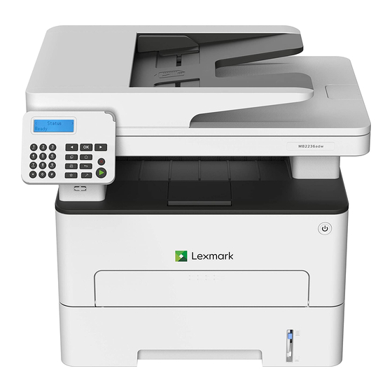
3400-48x General information Printer model configurations The Lexmark MB2236adw MFP is a small, monochrome, network‑capable, multifunction laser printer. Model Configurations Machine type/model MB2236adw Network-ready monochrome laser printer with 2‑line 3400‑481 LCD display, wireless capability, analog fax, internal duplex printing, and simplex scanning for small... - Page 20 3400-48x Paper size 250‑sheet tray Manual feeder Two‑sided Scanner glass Automatic printing document feeder Oficio (Mexico) 215.9 x 340.4 mm (8.5 x 13.4 in.) Hagaki 100 x 148 mm (3.94 x 5.83 in.) Statement 139.7 x 215.9 mm (5.5 x 8.5 in.) Executive 184.2 x 266.7 mm (7.25 x 10.5 in.)
-
Page 21: Supported Paper Types
3400-48x Paper size 250‑sheet tray Manual feeder Two‑sided Scanner glass Automatic printing document feeder DL Envelope 110 x 220 mm (4.33 x 8.66 in.) C5 Envelope 162 x 229 mm (6.38 x 9.01 in.) B5 Envelope 176 x 250 mm (6.93 x 9.84 in.) Universal Envelope 98.4 x 162 mm... -
Page 22: Supported Paper Weights
3400-48x Supported paper weights 250‑sheet tray Manual feeder Two‑sided printing Automatic document feeder ² ² ² ² 60–105 g/m (16–28‑lb 60–200 g/m (16–54‑lb 70–105 g/m (18.7–28‑lb 60–105 g/m (16–28‑lb bond) bond) bond) bond) Tools required for service • Flat-blade screwdrivers, various sizes •... -
Page 23: Diagnostics And Troubleshooting
3400-48x Diagnostics and troubleshooting Troubleshooting precautions CAUTION—SHOCK HAZARD: This product uses a soft power switch. It does not physically disconnect the input AC voltage. To avoid the risk of electrical shock, always remove the power cord from the printer when removal of the input AC voltage is required. CAUTION—SHOCK HAZARD: To avoid the risk of electrical shock and to prevent damage to the printer, remove the power cord from the electrical outlet and disconnect all connections to any external devices before you connect or disconnect any cable, electronic board, or assembly. -
Page 24: Troubleshooting Overview
3400-48x PRECAUCIÓN: PELIGRO DE ATRAPAMIENTO: Para evitar el riesgo de lesión por atrapamiento, preste atención en las áreas marcadas con esta etiqueta. Las lesiones por atrapamiento se pueden producir en torno a partes móviles, tales como engranajes, puertas, bandejas y cubiertas. Vorsichtsmaßnahmen bei der Fehlerbehebung VORSICHT –... -
Page 25: Fixing Print Quality Issues
3400-48x Fixing print quality issues Initial print quality check Before troubleshooting print problems, perform the following: • Make sure that the printer is located in an area that follows the recommended operating environment and power requirement specifications. • Check the status of supplies. Replace supplies that are low or empty. •... - Page 26 3400-48x Action Step 2 Go to step 3. The problem is solved. Make sure to remove the packing material on the toner cartridge and imaging unit. Does the problem remain? Step 3 Go to step 4. The problem is solved. Clear the paper path of debris and contamination.
- Page 27 3400-48x Action Step 7 Go to step 8. The problem is solved. Replace the imaging unit. Does the problem remain? Step 8 Go to step 10. Go to step 9. Check the HVPS toner contact spring for proper installation and damage.
- Page 28 3400-48x Action Step 12 Go to step 13. The problem is solved. Reseat the transfer roller. Enter the Diagnostics menu, and then select Advanced Print Quality Samples. Does the problem remain? Step 13 Go to step 14. The problem is solved.
-
Page 29: Solid Color Or Black Image Check
3400-48x Action Step 18 Go to step 19. The problem is solved. Make sure that the LVPS is compatible with the fuser and the printer. Make sure that the fuser connector has voltage. Make sure that the correct power input voltage is used. Does the problem remain? Step 19 Go to step 20. - Page 30 3400-48x Action Step 2 Go to step 3. The problem is solved. Make sure to remove the packing material on the toner cartridge and imaging unit. Does the problem remain? Step 3 Go to step 4. The problem is solved. Clear the paper path of debris and contamination.
- Page 31 3400-48x Action Step 7 Go to step 8. The problem is solved. Make sure that the toner cartridge is properly installed and free of damage. Make sure that the smart chip contacts are free of corrosion and contamination. Make sure that the developer roller surface is free of damage. Make sure that the toner HVPS contacts are free of corrosion and contamination.
-
Page 32: Blank Or White Pages Check
3400-48x Action Step 12 Contact the next The problem is level of support. solved. Replace the HVPS. See “HVPS removal” on page 231. Note: Make sure to perform the HVPS characterization when replacing the HVPS. Does the problem remain? Blank or white pages check Action Step 1 Go to step 2. - Page 33 3400-48x Action Step 4 Go to step 5. The problem is solved. Make sure that the imaging unit is properly installed and free of damage. Make sure that the smart chip contacts are free of corrosion and contamination. Make sure that the photoconductor roller surface is free of damage.
- Page 34 3400-48x Action Step 9 Go to step 10. The problem is solved. Replace the transfer roller. See “Transfer roller removal” on page 242. Does the problem remain? Step 10 Go to step 11. The problem is solved. Make sure that the toner cartridge is properly installed and free of damage.
- Page 35 3400-48x Action Step 14 Go to step 15. The problem is solved. Clean the printhead lens. Reseat the two printhead cables at both ends. Perform a print test. Does the problem remain? Step 15 Go to step 17. Go to step 16. Make sure that the printhead cables are properly connected.
-
Page 36: Dark Print Check
3400-48x Action Step 21 Contact the next Go to step 22. level of support. Check the controller board for proper installation and damage. Reseat all the cables on the controller board. Is the controller board properly installed and free of damage? Step 22 Contact the next The problem is... - Page 37 3400-48x Action Step 4 Go to step 5. The problem is solved. Make sure that the paper type is supported. Make sure that the paper type and size settings match the paper type and size set on the tray. Make sure that the paper has no damage or defects. Make sure that the paper tray guides are properly set.
- Page 38 3400-48x Action Step 9 Go to step 10. The problem is solved. Replace the imaging unit. Does the problem remain? Step 10 Go to step 12. Go to step 11. Check the HVPS toner contact spring for proper installation and damage.
- Page 39 3400-48x Action Step 14 Go to step 15. The problem is solved. Reseat the transfer roller. Enter the Diagnostics menu, and then select Advanced Print Quality Samples. Does the problem remain? Step 15 Go to step 16. The problem is solved.
-
Page 40: Light Print Check
3400-48x Light print check Action Step 1 Go to step 2. Go to step 3. Make sure that the toner cartridge is supported. Make sure that the toner cartridge and imaging unit are not empty. Check if the toner cartridge is new. Is the toner cartridge new? Step 2 Go to step 3. - Page 41 3400-48x Action Step 5 Go to step 6. The problem is solved. Adjust the toner darkness. Does the problem remain? Step 6 Go to step 7. The problem is solved. Make sure that the toner cartridge is properly installed and free of damage.
- Page 42 3400-48x Action Step 10 Go to step 12. Go to step 11. Check the HVPS toner contact spring for proper installation and damage. Check the toner smart chip contact for proper installation and damage. Check the toner contact spring for corrosion and contamination.
- Page 43 3400-48x Action Step 15 Go to step 16. The problem is solved. Replace the transfer roller. See “Transfer roller removal” on page 242. Does the problem remain? Step 16 Go to step 17. The problem is solved. Clean the printhead lens. Reseat the two printhead cables at both ends.
-
Page 44: Paper Curl Check
3400-48x Paper curl check Action Step 1 Go to step 2. The problem is solved. Clear the paper path of debris and contamination. Remove, and then insert the imaging unit and toner cartridge. Note: Shake the toner cartridge and imaging unit before inserting them. -
Page 45: Folded Or Wrinkled Paper Check
3400-48x Action Step 4 Go to step 6. Go to step 5. Enter the Diagnostics menu, and then navigate to: Printer diagnostics & adjustments > Motor tests Select Motor (transport). Open the rear door, and then check if the fuser exit rollers turn. Open the fuser access door, and then check if the hot rollers turn. - Page 46 3400-48x Action Step 1 Go to step 2. The problem is solved. Clear the paper path of debris and contamination. Remove, and then insert the imaging unit and toner cartridge. Note: Shake the toner cartridge and imaging unit before inserting them. Perform a POR.
-
Page 47: Repeating Defects Check
3400-48x Action Step 6 Contact the next Go to step 7. level of support. Reseat all the cables connected to the LVPS. Check the cables for proper connection and damage. Check the fuse for continuity. Check the electronic components on the LVPS for damage. Check the LVPS for proper installation and damage. - Page 48 3400-48x Action Step 3 Go to step 4. The problem is solved. Clear the paper path of debris and contamination. Remove, and then insert the imaging unit and toner cartridge. Note: Shake the toner cartridge and imaging unit before inserting them. Perform a POR.
- Page 49 3400-48x Action Step 10 Go to step 11. The problem is solved. Make sure that the toner cartridge is properly installed and free of damage. Make sure that the smart chip contacts are free of corrosion and contamination. Make sure that the developer roller surface is free of damage. Make sure that the toner HVPS contacts are free of corrosion and contamination.
- Page 50 3400-48x Action Step 16 Go to step 17. The problem is solved. Replace the transfer roller. See “Transfer roller removal” on page 242. Does the problem remain? Step 17 Go to step 18. Go to step 19. Measure the distance between the horizontal defects. Is the distance equal to 78.1 mm? Step 18 Go to step 19.
-
Page 51: Skewed Print Check
3400-48x Action Step 23 Contact the next Go to step 24. level of support. Make sure that the printhead cables are properly connected. Check the printhead for proper installation and damage. Is the printhead properly installed and free of damage? Step 24 Contact the next The problem is... - Page 52 3400-48x Action Step 3 Go to step 5. Go to step 4. Check the tray insert for proper installation and damage. Make sure that the separator roller is free of dust and contamination. Check the lift plate for proper operation. Check the paper guides for proper operation.
-
Page 53: Streaked Vertical Lines Appear On Prints Check
3400-48x Action Step 10 Contact the next Go to step 11. level of support. Make sure that the printhead cables are properly connected. Check the printhead for proper installation and damage. Is the printhead properly installed and free of damage? Step 11 Contact the next The problem is... - Page 54 3400-48x Action Step 4 Go to step 5. The problem is solved. Clean the printhead lens. Reseat the two printhead cables at both ends. Perform a print test. Does the problem remain? Step 5 Go to step 7. Go to step 6. Make sure that the printhead cables are properly connected.
- Page 55 3400-48x Action Step 10 Go to step 11. The problem is solved. Replace the toner cartridge. Does the problem remain? Step 11 Go to step 13. Go to step 12. Check the HVPS toner contact spring for proper installation and damage.
- Page 56 3400-48x Action Step 15 Go to step 16. The problem is solved. Reseat the transfer roller. Enter the Diagnostics menu, and then select Advanced Print Quality Samples. Does the problem remain? Step 16 Go to step 17. The problem is solved.
-
Page 57: Horizontal White Lines Check
3400-48x Horizontal white lines check Action Step 1 Go to step 2. Go to step 3. Make sure that the toner cartridge is supported. Make sure that the toner cartridge and imaging unit are not empty. Check if the toner cartridge is new. Is the toner cartridge new? Step 2 Go to step 3. - Page 58 3400-48x Action Step 5 Go to step 6. The problem is solved. Replace the imaging unit. Does the problem remain? Step 6 Go to step 7. The problem is solved. Make sure that the toner cartridge is properly installed and free of damage.
- Page 59 3400-48x Action Step 10 Contact the next The problem is level of support. solved. Check the imaging unit contact spring for damage and contamination. Make sure that the imaging unit contact spring is in proper contact with the HVPS. Is the imaging unit contact spring properly installed, and free of damage and contamination? Step 11 Go to step 12.
-
Page 60: Vertical White Lines Check
3400-48x Action Step 17 Go to step 18. Go to step 19. Reseat the HVPS cables. Check the cables for damage. Are the cables free of damage? Step 18 Contact the next The problem is level of support. solved. Replace the damaged cable. Does the problem remain? Step 19 Contact the next... - Page 61 3400-48x Action Step 2 Go to step 3. The problem is solved. Make sure to remove the packing material on the toner cartridge and imaging unit. Does the problem remain? Step 3 Go to step 4. The problem is solved. Clear the paper path of debris and contamination.
- Page 62 3400-48x Action Step 8 Go to step 9. The problem is solved. Replace the imaging unit. Does the problem remain? Step 9 Go to step 10. The problem is solved. Make sure that the toner cartridge is properly installed and free of damage.
- Page 63 3400-48x Action Step 13 Contact the next The problem is level of support. solved. Check the imaging unit contact spring for damage and contamination. Make sure that the imaging unit contact spring is in proper contact with the HVPS. Is the imaging unit contact spring properly installed, and free of damage and contamination? Step 14 Go to step 15.
-
Page 64: Vertical Colored Lines Or Banding Check
3400-48x Action Step 19 Contact the next Go to step 20. level of support. Check the HVPS characterization. Reseat the HVPS cables. Check the HVPS cables for proper installation and damage. Check the HVPS spring contact for proper connection to the board. - Page 65 3400-48x Action Step 3 Go to step 4. The problem is solved. Clear the paper path of debris and contamination. Remove, and then insert the imaging unit and toner cartridge. Note: Shake the toner cartridge and imaging unit before inserting them. Perform a POR.
- Page 66 3400-48x Action Step 9 Go to step 10. The problem is solved. Make sure that the toner cartridge is properly installed and free of damage. Make sure that the smart chip contacts are free of corrosion and contamination. Make sure that the developer roller surface is free of damage. Make sure that the toner HVPS contacts are free of corrosion and contamination.
- Page 67 3400-48x Action Step 14 Go to step 15. The problem is solved. Make sure that the transfer roller is properly installed and free of damage and contamination. Make sure that the HVPS contact spring is properly connected to the transfer roller. Make sure that the transfer roller spring is properly installed.
-
Page 68: Vertical Dark Streaks With Print Missing Check
3400-48x Action Step 20 Contact the next The problem is level of support. solved. Replace the HVPS. See “HVPS removal” on page 231. Note: Make sure to perform the HVPS characterization when replacing the HVPS. Does the problem remain? Vertical dark streaks with print missing check Action Step 1 Go to step 2. - Page 69 3400-48x Action Step 4 Go to step 5. The problem is solved. Clean the printhead lens. Reseat the two printhead cables at both ends. Perform a print test. Does the problem remain? Step 5 Go to step 7. Go to step 6. Make sure that the printhead cables are properly connected.
- Page 70 3400-48x Action Step 10 Go to step 11. The problem is solved. Replace the toner cartridge. Does the problem remain? Step 11 Go to step 13. Go to step 12. Check the HVPS toner contact spring for proper installation and damage.
- Page 71 3400-48x Action Step 15 Go to step 16. The problem is solved. Reseat the transfer roller. Enter the Diagnostics menu, and then select Advanced Print Quality Samples. Does the problem remain? Step 16 Go to step 17. The problem is solved.
-
Page 72: White Streaks And Voided Areas Check
3400-48x White streaks and voided areas check Action Step 1 Go to step 2. Go to step 3. Make sure that the toner cartridge is supported. Make sure that the toner cartridge and imaging unit are not empty. Check if the toner cartridge is new. Is the toner cartridge new? Step 2 Go to step 3. - Page 73 3400-48x Action Step 5 Go to step 6. The problem is solved. Replace the imaging unit. Does the problem remain? Step 6 Go to step 7. The problem is solved. Make sure that the toner cartridge is properly installed and free of damage.
- Page 74 3400-48x Action Step 10 Contact the next The problem is level of support. solved. Check the imaging unit contact spring for damage and contamination. Make sure that the imaging unit contact spring is in proper contact with the HVPS. Is the imaging unit contact spring properly installed, and free of damage and contamination? Step 11 Go to step 12.
-
Page 75: Clipped Pages Or Images Check
3400-48x Action Step 17 Go to step 18. Go to step 19. Reseat the HVPS cables. Check the cables for damage. Are the cables free of damage? Step 18 Contact the next The problem is level of support. solved. Replace the damaged cable. Does the problem remain? Step 19 Contact the next... - Page 76 3400-48x Action Step 2 Go to step 3. The problem is solved. Make sure to remove the packing material on the toner cartridge and imaging unit. Does the problem remain? Step 3 Go to step 4. The problem is solved. Clear the paper path of debris and contamination.
- Page 77 3400-48x Action Step 7 Go to step 8. The problem is solved. Replace the toner cartridge. Does the problem remain? Step 8 Go to step 10. Go to step 9. Check the HVPS toner contact spring for proper installation and damage.
- Page 78 3400-48x Action Step 12 Go to step 13. The problem is solved. Reseat the transfer roller. Enter the Diagnostics menu, and then select Advanced Print Quality Samples. Does the problem remain? Step 13 Go to step 14. The problem is solved.
-
Page 79: Compressed Images Appear On Prints Check
3400-48x Action Step 20 Go to step 21. The problem is solved. Replace the HVPS. See “HVPS removal” on page 231. Note: Make sure to perform the HVPS characterization when replacing the HVPS. Does the problem remain? Step 21 Contact the next Go to step 22. - Page 80 3400-48x Action Step 1 Go to step 2. The problem is solved. Clear the paper path of debris and contamination. Remove, and then insert the imaging unit and toner cartridge. Note: Shake the toner cartridge and imaging unit before inserting them. Perform a POR.
- Page 81 3400-48x Action Step 6 Go to step 8. Go to step 7. Remove the imaging unit. Check the coupling drive gear for proper installation and damage. Actuate the lever, and then check if the coupling drive gear engages. Is the coupling drive gear properly installed and free of damage? Step 7 Go to step 8.
-
Page 82: Incorrect Margins On Prints Check
3400-48x Action Step 13 Contact the next The problem is level of support. solved. Reseat the deskew solenoid cable at both ends. Does the problem remain? Step 14 Go to step 15. Go to step 16. Enter the Diagnostics menu, and then navigate to: Printer diagnostics &... - Page 83 3400-48x Action Step 1 Go to step 2. The problem is solved. Clear the paper path of debris and contamination. Remove, and then insert the imaging unit and toner cartridge. Note: Shake the toner cartridge and imaging unit before inserting them. Perform a POR.
-
Page 84: Toner Rubs Off Check
3400-48x Action Step 6 Go to step 7. The problem is solved. Clean the printhead lens. Reseat the two printhead cables at both ends. Perform a print test. Does the problem remain? Step 7 Go to step 9. Go to step 8. Make sure that the printhead cables are properly connected. - Page 85 3400-48x Action Step 1 Go to step 2. Go to step 3. Make sure that the toner cartridge is supported. Make sure that the toner cartridge and imaging unit are not empty. Check if the toner cartridge is new. Is the toner cartridge new? Step 2 Go to step 3.
-
Page 86: Toner Specks Appear On Prints Check
3400-48x Action Step 6 Go to step 7. The problem is solved. Replace the fuser. See “Fuser removal” on page 245. Does the problem remain? Step 7 Contact the next Go to step 8. level of support. Reseat all the cables connected to the LVPS. Check the cables for proper connection and damage. - Page 87 3400-48x Action Step 2 Go to step 3. The problem is solved. Make sure to remove the packing material on the toner cartridge and imaging unit. Does the problem remain? Step 3 Go to step 4. The problem is solved. Clear the paper path of debris and contamination.
- Page 88 3400-48x Action Step 7 Go to step 8. The problem is solved. Replace the toner cartridge. Does the problem remain? Step 8 Go to step 10. Go to step 9. Check the HVPS toner contact spring for proper installation and damage.
-
Page 89: Paper Jams
3400-48x Action Step 12 Go to step 13. The problem is solved. Reseat the transfer roller. Enter the Diagnostics menu, and then select Advanced Print Quality Samples. Does the problem remain? Step 13 Go to step 14. The problem is solved. - Page 90 3400-48x Correct loading of paper Incorrect loading of paper • Do not load or remove a tray while the printer is printing. • Do not load too much paper. Make sure that the stack height is below the maximum paper fill indicator. •...
-
Page 91: 200 Paper Jams
3400-48x 200 paper jams 200 paper jam messages Error code Description Action 200.04 Paper fed from the manual feeder cleared the “Sensor (input sensor S3) service check” on sensor (input sensor S3) earlier than expected. page 200.05 Paper fed from the manual feeder never cleared the sensor (input sensor S3). - Page 92 3400-48x Action Step 2 Go to step 3. The problem is solved. Remove the imaging unit and toner cartridge, and then make sure that the paper path is free of jams and obstructions. Clear all rollers of dirt and contamination. Does the problem remain? Step 3 Go to step 4.
- Page 93 3400-48x Action Step 8 Go to step 10. Go to step 9. Check the sensor flags for proper installation and damage. Check the sensor flags for proper alignment with the sensors. Check the sensor flag springs for proper installation and damage.
- Page 94 3400-48x Sensor (input sensor S3) service check Action Step 1 Go to step 2. The problem is solved. Make sure that the tray insert is properly inserted. Make sure that the paper type and size settings match the paper type and size set on the tray. Make sure that the duplex unit is properly inserted.
- Page 95 3400-48x Action Step 7 Go to step 10. Go to step 8. Enter the Diagnostics menu, and then navigate to: Printer diagnostics & adjustment > Sensor tests Find the following sensors: • Sensor (media present in tray1 S1) • Sensor (input sensor S3) •...
- Page 96 3400-48x Action Step 14 Go to step 15. Go to step 16. Enter the Diagnostics menu, and then navigate to: Printer diagnostics & adjustments > Motor tests Select Motor (transport drive). Did the motor run? Step 15 Go to step 16. The problem is solved.
-
Page 97: 202 Paper Jams
3400-48x 202 paper jams 202 paper jam messages Error code Description Action 202.03 Paper fed from the manual feeder never “Sensor (fuser exit sensor S4) service check” arrived at the sensor (fuser exit sensor S4). on page 202.05 Paper fed from the manual feeder never “Sensor (fuser exit sensor S4) never cleared cleared the sensor (fuser exit sensor S4). - Page 98 3400-48x Action Step 4 Go to step 7. Go to step 5. Enter the Diagnostics menu, and then navigate to: Printer diagnostics & adjustments > Sensor tests Find the sensor (fuser exit sensor S4). Does the sensor status change while toggling the sensor? Step 5 Go to step 7.
- Page 99 3400-48x Action Step 11 Go to step 12. The problem is solved. Replace the rear door. See “Rear door removal” on page 243. Does the problem remain? Step 12 Go to step 13. Go to step 14. Enter Diagnostics menu, and then navigate to: Printer diagnostics &...
- Page 100 3400-48x Action Step 18 Contact the next The problem is level of support. solved. Reseat the deskew solenoid cable at both ends. Does the problem remain? Step 19 Go to step 20. Go to step 21. Enter the Diagnostics menu, and then navigate to: Printer diagnostics &...
- Page 101 3400-48x Sensor (fuser exit sensor S4) never cleared service check Action Step 1 Go to step 2. The problem is solved. Make sure that the tray insert is properly inserted. Make sure that the paper type and size settings match the paper type and size set on the tray.
- Page 102 3400-48x Action Step 7 Go to step 10. Go to step 8. Enter the Diagnostics menu, and then navigate to: Printer diagnostics & adjustment > Sensor tests Find the following sensors: • Sensor (media present in tray1 S1) • Sensor (input sensor S3) •...
- Page 103 3400-48x Action Step 13 Go to step 15. Go to step 14. Check the fuser cables for proper connection and damage. Check the fuser access door for damage. Check if the fuser gears are in proper contact with the drive gears.
- Page 104 3400-48x Action Step 20 Go to step 21. Go to step 22. Enter the Diagnostics menu, and then navigate to: Printer diagnostics & adjustments > Motor tests Select Motor (transport drive). Did the motor run? Step 21 Go to step 22. The problem is solved.
- Page 105 3400-48x Sensor (fuser exit sensor S4) static jam service check Action Step 1 Go to step 2. The problem is solved. Make sure that the tray insert is properly inserted. Make sure that the paper type and size settings match the paper type and size set on the tray.
- Page 106 3400-48x Action Step 7 Go to step 10. Go to step 8. Enter the Diagnostics menu, and then navigate to: Printer diagnostics & adjustment > Sensor tests Find the following sensors: • Sensor (media present in tray1 S1) • Sensor (input sensor S3) •...
-
Page 107: 206 Paper Jams
3400-48x 206 paper jams 206 paper jam messages Error code Description Action 206.15 Paper fed from tray remains on the sensor “Sensor (staging sensor S2): Paper failed to (fuser exit sensor S4). clear service check” on page 107. 206.16 Paper fed from tray 1 never arrived at the “Sensor (staging sensor S2): Paper failed to sensor (staging sensor S2). - Page 108 3400-48x Action Step 5 Go to step 7. Go to step 6. Check the sensor for proper installation and damage. Check the alignment with the sensor flag. Check the sensor cable for proper connection and damage. Is the sensor properly installed and free of damage? Step 6 Go to step 7.
- Page 109 3400-48x Action Step 12 Go to step 14. Go to step 13. Enter the Diagnostics menu, and then navigate to: Input tray quick print > Tray 1 > Single Check if the clip in the middle of the solenoid turns when the paper is transported.
- Page 110 3400-48x Action Step 19 Contact the next The problem is level of support. solved. Replace the controller board. See “Controller board removal” on page 228. Does the problem remain? Sensor (staging sensor S2): Paper failed to arrive service check Action Step 1 Go to step 2.
- Page 111 3400-48x Action Step 5 Go to step 7. Go to step 6. Check the sensor for proper installation and damage. Check the alignment with the sensor flag. Check the sensor cable for proper connection and damage. Is the sensor properly installed and free of damage? Step 6 Go to step 7.
- Page 112 3400-48x Action Step 12 Go to step 13. The problem is solved. Clear the pick rollers of contamination. Reseat the pick rollers. Enter the Diagnostics menu, and then navigate to: Input tray quick print > Tray 1 > Single. Does the problem remain? Step 13 Go to step 15.
-
Page 113: 232 Paper Jams
3400-48x Action Step 19 Go to step 20. The problem is solved. Enter the Diagnostics menu, and then navigate to: Input tray quick print > Tray 1 > Single Enter the Diagnostics menu, and then navigate to: Input tray quick print > Duplex > Single Does the problem remain? Step 20 Go to step 21. - Page 114 3400-48x Sensor (input sensor S3): Duplex failure service check Action Step 1 Go to step 2. The problem is solved. Make sure that the tray insert is properly inserted. Make sure that the paper type and size settings match the paper type and size set on the tray.
- Page 115 3400-48x Action Step 7 Go to step 10. Go to step 8. Enter the Diagnostics menu, and then navigate to: Printer diagnostics & adjustment > Sensor tests Find the following sensors: • Sensor (media present in tray1 S1) • Sensor (input sensor S3) •...
- Page 116 3400-48x Action Step 13 Go to step 15. Go to step 14. Reseat the duplex unit. Check the duplex unit gears for damage. Check the rollers and belts for wear and contamination. Is the duplex unit properly installed and free of damage? Step 14 Go to step 15.
-
Page 117: User Attendance Messages
The printer has detected a non‑Lexmark supply or part installed in the printer. The Lexmark printer is designed to function best with genuine Lexmark supplies and parts. Use of third-party supplies or parts may affect the performance, reliability, or life of the printer and its imaging components. -
Page 118: 8-12 User Attendance Messages
Action Step 1 Go to step 2. The problem is solved. Make sure that the imaging unit and toner cartridge is a genuine Lexmark supply. Does the problem remain? Step 2 Go to step 3. The problem is solved. Shake the toner cartridge. - Page 119 3400-48x Action Step 3 Go to step 4. The problem is solved. Replace the toner cartridge. Does the problem remain? Step 4 Go to step 5. The problem is solved. Shake the imaging unit. Clean the imaging unit smart chip contacts, and then check the contacts for damage.
- Page 120 3400-48x Action Step 10 Contact the next Go to step 11. level of support. Reseat all the cables on the controller board. Check if the controller board LED lights up. Check the controller board for proper installation and damage. Is the controller board properly installed and free of damage? Step 11 Contact the next The problem is...
-
Page 121: 31-33 User Attendance Messages
Action Step 1 Go to step 2. The problem is solved. Make sure that the imaging unit and toner cartridge is a genuine Lexmark supply. Does the problem remain? Step 2 Go to step 3. The problem is solved. Shake the toner cartridge. - Page 122 3400-48x Action Step 3 Go to step 4. The problem is solved. Replace the toner cartridge. Does the problem remain? Step 4 Go to step 5. The problem is solved. Shake the imaging unit. Clean the imaging unit smart chip contacts, and then check the contacts for damage.
- Page 123 3400-48x Action Step 10 Contact the next Go to step 11. level of support. Reseat all the cables on the controller board. Check if the controller board LED lights up. Check the controller board for proper installation and damage. Is the controller board properly installed and free of damage? Step 11 Contact the next The problem is...
- Page 124 3400-48x Action Step 5 Go to step 7. Go to step 6. Check the smart chip for proper installation and damage. Is the smart chip properly installed and free of damage? Step 6 Go to step 7. The problem is solved.
- Page 125 Step 1 Go to step 2. The problem is solved. Remove, and then make sure that the imaging unit and toner cartridge are genuine Lexmark supplies. Does the problem remain? Step 2 Go to step 3. The problem is solved.
-
Page 126: 34-42 User Attendance Errors
3400-48x Action Step 6 Go to step 7. The problem is solved. Replace the imaging unit. Does the problem remain? Step 7 Go to step 9. Go to step 8. Check the cables for proper connection and damage. Are the cables properly connected and free of damage? Step 8 Go to step 9. - Page 127 3400-48x Error code Description Action 42.xy Toner cartridge region does not match the printer “Toner cartridge service check” on region. page 129. • x = printer region • y = toner cartridge region Scanner collation area service check Action Step 1 Go to step 2.
- Page 128 3400-48x Action Step 8 Go to step 9. The problem is solved. Upgrade the firmware. Note: Contact your next level of support for the correct firmware level to use. Perform a POR. Perform a print test. Does the problem remain? Step 9 Contact the next Go to step 10.
- Page 129 Action Step 1 Go to step 2. The problem is solved. Make sure that the imaging unit and toner cartridge is a genuine Lexmark supply. Does the problem remain? Step 2 Go to step 3. The problem is solved. Shake the toner cartridge.
-
Page 130: 55 User Attendance Messages
3400-48x Action Step 4 Go to step 5. Go to step 7. From the control panel home screen, go to Settings > Reports > Device > Device statistics. Check if the install date reflects the date you replaced the cartridge. Check the supply level and capacity of the toner cartridge. - Page 131 3400-48x Unsupported USB device service check Action Step 1 Go to step 2. The problem is solved. Turn off the printer. Disconnect the power cord. Wait for 10 seconds, and then turn on the printer. Does the problem remain? Step 2 Go to step 4.
-
Page 132: 71 User Attendance Messages
3400-48x Action Step 8 Contact the next Go to step 9. level of support. Reseat all the cables on the controller board. Check if the controller board LED lights up. Check the controller board for proper installation and damage. Is the controller board properly installed and free of damage? Step 9 Contact the next The problem is... - Page 133 3400-48x Analog phone line service check Action Step 1 Go to step 2. The problem is solved. Turn off the printer. Disconnect the power cord. Wait for 10 seconds, and then turn on the printer. Does the problem remain? Step 2 Go to step 3.
-
Page 134: 84 User Attendance Messages
3400-48x 84 user attendance messages 84 user attendance messages Error code Description Action 84.01 The imaging unit is nearly low. “Toner cartridge or imaging unit low service check” on page 135. 84.02 84.11 The imaging unit is low. 84.12 84.13 84.19 84.21 The imaging unit is very low. - Page 135 Step 1 Go to step 2. The problem is solved. Make sure that the imaging unit and toner cartridge are genuine Lexmark supplies. Does the problem remain? Step 2 Go to step 3. Go to step 4. From the control panel, navigate to Settings > Reports > Device >...
- Page 136 3400-48x Action Step 7 Go to step 9. Go to step 8. Check the smart chip for proper installation and damage. Is the smart chip properly installed and free of damage? Step 8 Go to step 9. The problem is solved.
-
Page 137: 88 User Attendance Messages
3400-48x 88 user attendance messages 88 user attendance messages Error code Description Action 88.00 The toner cartridge is nearly low. “Toner cartridge or imaging unit low service check” on page 135. 88.09 88.10 The toner cartridge is low. 88.19 88.20 The toner cartridge is very low. - Page 138 3400-48x Action Step 2 Go to step 3. The problem is solved. Replace the top cover. See “Top cover removal” on page 248. Does the problem remain? Step 3 Contact the next Go to step 4. level of support. Reseat all the cables on the controller board. Check if the controller board LED lights up.
- Page 139 3400-48x Action Step 4 Go to step 6. Go to step 5. Make sure that the separator roller is free of dust and contamination. Make sure that the lift plate is properly working. Make sure that the paper guides are properly working. Check the tray insert for proper installation and damage.
- Page 140 3400-48x Action Step 10 Go to step 12. Go to step 11. Check the sensor for proper installation and damage. Check the alignment with the sensor flag. Check the sensor cable for proper connection and damage. Is the sensor properly installed and free of damage? Step 11 Go to step 12.
- Page 141 3400-48x Insufficient memory service check Action Step 1 Go to step 2. The problem is solved. Perform a POR. Send a simple print job with no image. Does the problem remain? Step 2 Go to step 3. The problem is solved.
-
Page 142: Printer Hardware Errors
3400-48x Printer hardware errors 111 error messages 111 error messages Error code Description Action 111.20 Printhead error (mirror motor lock) was detected “Printhead error 1 service check” on before the motor was turned on. page 153. 111.21 No printhead power (+5V) when the laser servo started. -
Page 143: 121 Errors
3400-48x 121 errors 121 error messages Error code Description Action 121.00 The fuser failed to reach temperature during “Fuser service check” on page 144. warm‑up. 121.01 Attempting to heat the fuser, but the fuser is not installed. 121.02 Attempting to power up the fuser while it is too warm (belt: 50°C, lamp: 76°C) to execute EWC/line voltage detection after a Wrong Fuser Installed error had been previously... - Page 144 3400-48x Error code Description Action 121.33 The fuser is too cold when the paper is in the fuser. See “Fuser service check” on page 144. 121.34 The fuser is too cold during steady state control when paper is not in the fuser. Note: This event can occur during printing or standby modes.
- Page 145 3400-48x Action Step 4 Go to step 5. The problem is solved. Perform a POR. Enter the Diagnostics menu, and then navigate to: Input tray quick print > Tray 1 > Single Does the problem remain? Step 5 Go to step 6. Go to step 7.
- Page 146 3400-48x Action Step 10 Go to step 11. The problem is solved. Replace the fan. See “Fan assembly removal” on page 237. Does the problem remain? Step 11 Go to step 12. The problem is solved. Replace the damaged cable. Does the problem remain? Step 12 Go to step 15.
-
Page 147: 126 Errors
3400-48x Action Step 17 Go to step 18. The problem is solved. Make sure that the main drive is properly installed and free of damage. Make sure that the main drive gears are properly installed. Make sure that the drive gears are in proper contact with the gear they are driving. - Page 148 3400-48x LVPS service check Action Step 1 Go to step 2. The problem is solved. Remove the imaging unit and toner cartridge, and then make sure that the paper path is free of jams and obstructions. Clear all rollers of dirt and contamination. Does the problem remain? Step 2 Go to step 3.
-
Page 149: 140 Errors
3400-48x Action Step 7 Contact the next The problem is level of support. solved. Replace the controller board. See “Controller board removal” on page 228. Does the problem remain? 140 errors 140 error messages Error code Description Action 140.82 Motor (transport drive) failure. “Motor (transport drive) service check”... -
Page 150: 6Yy Errors
3400-48x Action Step 4 Go to step 6. Go to step 5. Enter the Diagnostics menu, and then navigate to: Printer diagnostics & adjustments > Motor tests Select Motor (transport drive). Does the motor run? Step 5 Go to step 6. Contact the next level of support. - Page 151 3400-48x Error code Description Action 600.04 Duplex paper was never picked. “Printer declared jam service check” on page 152. 600.05 Invalid printhead NVRAM type. “Printhead error 1 service check” on page 153. 600.06 No response from the paper port driver. “Printer declared jam service check”...
- Page 152 3400-48x Printer declared jam service check Action Step 1 Go to step 2. The problem is solved. Shake the toner cartridge. Clean the toner cartridge smart chip contacts, and then check the contacts for damage. Clean the toner cartridge spring contacts, and then check the contacts for damage.
- Page 153 3400-48x Action Step 8 Contact the next The problem is level of support. solved. Replace the controller board. See “Controller board removal” on page 228. Does the problem remain? Printhead error 1 service check Action Step 1 Go to step 2. The problem is solved.
- Page 154 3400-48x Action Step 7 Contact the next Go to step 8. level of support. Reseat all the cables on the controller board. Check if the controller board LED lights up. Check the controller board for proper installation and damage. Is the controller board properly installed and free of damage? Step 8 Contact the next The problem is...
- Page 155 3400-48x Action Step 5 Go to step 8. Go to step 6. Enter the Diagnostics menu, and then navigate to: Printer diagnostics & adjustment > Sensor tests Find the following sensors: • Sensor (media present in tray1 S1) • Sensor (input sensor S3) •...
-
Page 156: Procedure Before Starting The 9Yy Service Checks
3400-48x Action Step 12 Go to step 13. The problem is solved. Replace the damaged cable. Does the problem remain? Step 13 Contact the next Go to step 14. level of support. Reseat all the cables on the controller board. Check if the controller board LED lights up. -
Page 157: 9Yy Errors
3400-48x • Some printers are designed to restart automatically after a 9yy error. On these printers, you can retrieve the secondary crash code information using the SE menu. Open a web browser, type http://printer_IP_address/se, and then press Enter. Click Logs Gzip Compressed. Note: A logs.tar.gz file is saved to the Downloads folder. - Page 158 3400-48x Error code Description Action 938.04 Supplies security is not enabled. “Black imaging unit or photoconductor smart chip or sensor problem service check” on page 123. Diagnostics and troubleshooting...
- Page 159 3400-48x Error code Description Action RIP to engine communication failure. “Engine error service check” on page 165. Engine card failure. Engine card—Pel clock check failed. Engine card—Delay line calibration failure. Non-Generic FRU installed. Mismatch between system NVRAM part and mirror NVRAM part. Note: .xx points to the setting that does not match.
- Page 160 156. Determine the operating system used when the error occurred. If possible, determine whether a PostScript or PCL file was sent to the printer when the error occurred. Ask the customer which Lexmark Solutions applications are installed on the printer.
- Page 161 3400-48x Action Step 1 Go to step 2. The problem is solved. Perform a POR. Does the error remain? Step 2 Go to step 3. Go to step 6. Write down the exact 900.xx error code that appears on the display.
- Page 162 3400-48x Action Step 7 Go to step 8. Go to step 10. Note: Before performing this step, write down the following information about the file being sent to the printer: • Application used • Operating system • Driver type • File type (PCL, PostScript, XPS, etc.) Reattach the communications cable.
- Page 163 Perform a print job. Does the problem remain? Step 15 Go to step 31. The problem is solved. Install a Lexmark‑recommended optional memory. Perform a print job. Does the problem remain? Step 16 Go to step 17. Go to step 21.
- Page 164 3400-48x Action Step 22 Go to step 24. Go to step 23. Reinstall the first optional ISP. Reset the printer. Does the problem remain? Step 23 Go to step 24. Go to step 26. Perform a job to test the option. Does the problem remain? Step 24 Go to step 25.
- Page 165 3400-48x Action Step 29 Go to step 30. Go to step 26. Upgrade the firmware if it was not upgraded in a previous step. Note: Contact your next level of support for the correct firmware level to use. Reset the printer. Send a print job.
- Page 166 3400-48x Action Step 3 Go to step 5. Go to step 4. Check the cables for proper connection and damage. Are the cables properly connected and free of damage? Step 4 Go to step 5. The problem is solved. Replace only the damaged cable. Does the problem remain? Step 5 Contact the next...
- Page 167 3400-48x Action Step 4 Go to step 5. Go to step 9. Check controller board ports and pins for damage. Are the controller board ports and pins free of damage? Step 5 Go to step 6. Go to step 9. Make sure that the Wi-Fi is connected to the network.
-
Page 168: Adf/Scanner Hardware Errors
3400-48x ADF/Scanner hardware errors 84y error messages Error code Description Action 840.01 The scanner is disabled by the administrator. “Scanner disabled and scanner communication error service check” on 840.02 The scanner is disabled for other reasons. For page 175. example, invalid license, and too many hardware errors. - Page 169 3400-48x Action Step 4 Go to step 5. The problem is solved. Replace the ADF pick assembly. See “ADF pick assembly removal” on page 260. Does the problem remain? Step 5 Go to step 8. Go to step 6. Enter the Diagnostics menu, and then navigate to: Scanner diagnostics >...
-
Page 170: Sensor (Adf Top Door Interlock) Service Check
3400-48x Action Step 12 Go to step 14. Go to step 13. Enter the Diagnostics menu, and then navigate to: Scanner diagnostics > Motor tests Select Motor (ADF transport). Does the motor run? Step 13 Go to step 15. Go to step 14. Reseat the ADF cable. - Page 171 3400-48x Action Step 2 Go to step 5. Go to step 3. Enter the Diagnostics menu, and then navigate to: Scanner diagnostics > Sensor tests Find the sensor (ADF top door interlock). Does the sensor status change while toggling the sensor? Step 3 Go to step 4.
- Page 172 3400-48x Action Step 9 Go to step 10. The problem is solved. Replace the ADF pick assembly. See “ADF pick assembly removal” on page 260. Does the problem remain? Step 10 Go to step 12. Go to step 11. Enter the Diagnostics menu, and then navigate to: Scanner diagnostics >...
-
Page 173: Adf Feed Error Service Check
3400-48x ADF feed error service check Action Step 1 Go to step 2. The problem is solved. Open the ADF door, and then remove the jammed paper. Make sure that the paper path is free of obstructions. Raise the ADF assembly, and then make sure that the scan area is free of dust and obstructions. - Page 174 3400-48x Action Step 7 Go to step 8. The problem is solved. Clean the ADF pick rollers and separator pad. Enter the Diagnostics menu, and then navigate to: Scanner diagnostics > Feed test Does the problem remain? Step 8 Go to step 10. Go to step 9.
-
Page 175: Scanner Disabled And Scanner Communication Error Service Check
3400-48x Action Step 14 Contact the next The problem is level of support. solved. Replace the controller board. See “Controller board removal” on page 228. Does the problem remain? Scanner disabled and scanner communication error service check Action Step 1 Go to step 2. -
Page 176: Flatbed Home Position Service Check
3400-48x Action Step 6 Go to step 9. Go to step 7. Reseat all the scanner cables on the controller board. Enter the Diagnostics menu, and then navigate to: Scanner diagnostics > Motor tests > Flatbed scanner Did the motor run? Step 7 Go to step 9. -
Page 177: Other Symptoms
3400-48x Action Step 3 Go to step 6. Go to step 4. Reseat all the scanner cables on the controller board. Enter the Diagnostics menu, and then navigate to: Scanner diagnostics > Motor tests > Flatbed scanner Did the motor run? Step 4 Go to step 6. -
Page 178: Door Switch Service Check
3400-48x Symptom Action No display. “No display service check” on page 185. No power. “No power service check” on page 186. ADF door is open. “ADF door open service check” on page 187. Door switch service check Action Step 1 Go to step 3. -
Page 179: Load Tray 1 With A4 Plain Paper Service Check
3400-48x Load tray 1 with A4 plain paper service check Action Step 1 Go to step 2. The problem is solved. Make sure that the tray insert is properly inserted. Make sure that the paper is properly loaded in the tray. Make sure that the paper type and size settings match the paper type and size set on the tray. - Page 180 3400-48x Action Step 6 Go to step 8. Go to step 7. Check the sensor flags for proper installation and damage. Check the sensor flags for proper alignment with the sensors. Check the sensor flag springs for proper installation and damage.
-
Page 181: Paper Did Not Arrive In The Bin Service Check
3400-48x Paper did not arrive in the bin service check Action Step 1 Go to step 2. The problem is solved. Make sure that the tray insert is properly inserted. Make sure that the paper type and size settings match the paper type and size set on the tray. - Page 182 3400-48x Action Step 7 Go to step 9. Go to step 8. Make sure that the redrive gears are in proper contact with the printer drive gears. Check the redrive gears for proper installation and damage. Check the roller for wear, contamination, and damage. Is the redrive properly installed and free of damage? Step 8 Go to step 9.
-
Page 183: Tray Insert Obstructed Service Check
3400-48x Tray insert obstructed service check Action Step 1 Go to step 2. The problem is solved. Make sure that the tray insert is properly inserted. Make sure that the paper is properly loaded in the tray. Make sure that the paper type and size settings match the paper type and size set on the tray. -
Page 184: Fax Not Detected Service Check
3400-48x Action Step 4 Go to step 5. Go to step 6. Enter the Diagnostics menu, and then navigate to: Printer diagnostics & adjustments > Motor tests Select Motor (transport drive). Did the motor run? Step 5 Go to step 6. The problem is solved. -
Page 185: No Display Service Check
3400-48x Action Step 2 Go to step 3. The problem is solved. Replace the top cover. See “Top cover removal” on page 248. Does the problem remain? Step 3 Contact the next Go to step 4. level of support. Reseat all the cables on the controller board. Check if the controller board LED lights up. -
Page 186: No Power Service Check
3400-48x Action Step 5 Contact the next The problem is level of support. solved. Replace the controller board. See “Controller board removal” on page 228. Does the problem remain? No power service check Action Step 1 Go to step 5. Go to step 2. -
Page 187: Adf Door Open Service Check
3400-48x Action Step 7 Contact the next Go to step 8. level of support. Reseat all the cables on the controller board. Check if the controller board LED lights up. Check the controller board for proper installation and damage. Is the controller board properly installed and free of damage? Step 8 Contact the next The problem is... - Page 188 3400-48x Action Step 5 Go to step 7. Go to step 6. Reseat the ADF cable. Check the ADF cable for proper connection and damage. Check the ADF assembly for proper installation and damage. Check the ADF door sensor for damage. Is the ADF assembly properly installed and free of damage? Step 6 Go to step 7.
-
Page 189: Service Menus
3400-48x Service menus Understanding the printer control panel Using the control panel Control panel part Function Display • View printer messages and supply status. • Set up and operate the printer. Left arrow button • Scroll through menus or move between screens and menu options. •... -
Page 190: Understanding The Status Of The Power Button And Indicator Light
3400-48x Understanding the status of the power button and indicator light Indicator light Printer status The printer is off or in Hibernate mode. Blinking green The printer is ready or processing data. Blinking red The printer requires user intervention. Power button light Printer status The printer is off, ready, or processing data. -
Page 191: Format Fax Storage
3400-48x Format Fax Storage This setting deletes stored fax jobs. Enter the Diagnostics menu, and then navigate to: Format Fax Storage > Format Fax Storage Press Event Log Display Log This setting displays the panel text that appears when the event occurs. Enter the Diagnostics menu, and then navigate to: Event Log >... -
Page 192: Input Tray Quick Print
3400-48x Mark Log This setting allows you to create a service, maintenance, or custom log entry. Each log entry is added in the printer event log. Enter the Diagnostics menu, and then navigate to: Event Log > Mark Log Select a log that you want to create, and then press Input tray quick print This setting lets you print a single or continuous Quick test page in either duplex or simplex mode. - Page 193 3400-48x Processor ID This setting indicates the ID of the processor on the controller board. Enter the Diagnostics menu, and then navigate to: Printer Setup > Processor ID View the processor ID. Serial number This setting displays a read-only value of the printer serial number. Enter the Diagnostics menu, and then navigate to: Printer Setup >...
-
Page 194: Printer Diagnostics & Adjustments
3400-48x Printer diagnostics & adjustments Sensor tests Enter the Diagnostics menu, and then select Printer diagnostics & adjustments. A list of sensor tests appears. Find, and then manually toggle the sensor. Notes: • The sensor status on the screen toggles between 1 and 0 when the sensor is properly working. •... -
Page 195: Scanner Diagnostics
3400-48x Registration adjust This setting lets you adjust the skew, margins, or print a Quick test page. Enter the Diagnostics menu, and then navigate to: Printer diagnostics & adjustments > Registration adjust Select a setting to adjust. Universal Override This setting allows the user to feed custom media sizes to a Custom Media Tray. Enter the Diagnostics menu, and then navigate to: Printer diagnostics &... - Page 196 3400-48x Sensor Tests This test verifies the status of the scanner sensors. Enter the Diagnostics menu, and then navigate to: Scanner Diagnostics > Sensor Test Select a sensor, and then press Find, and then manually toggle the sensor. Notes: • The sensor status on the screen toggles between 1 and 0 when the sensor is properly working.
-
Page 197: Config Menu
3400-48x Notes: • If the back side of the copy has vertical streaks, then clean the scanner glass and scanner glass pad, and then print another copy. • If the streaks still appear, then repeat the cleaning and verification procedure or replace the ADF. Config menu Entering the Config menu The Config menu consists of menus, settings, and operations that are used to configure the printer. - Page 198 3400-48x Menu item Description Tray Configuration Set the paper source that the user fills when a prompt to load paper or envelope appears. Paper Prompts Auto* Manual Paper Envelope Prompts Auto* Manual Envelope Tray Configuration Set the printer to resolve paper- or envelope-related change prompts.
-
Page 199: Service Engineer Menu
3400-48x Menu item Description Device Operations Erase all custom messages. Clear Custom Status Scanner Configuration Print a Quick Test target page. Scanner Manual Registration Note: Make sure that the margin spacing on the target page Print Quick Test is uniform all the way around the target. If it is not, then the printer margins may need to be reset. -
Page 200: Entering The Service Engineer (Se) Menu
3400-48x Entering the Service Engineer (SE) menu This contains several functions that a service engineer may need in order to diagnose and fix problems on the printer. To access the SE menu, press Back, Left arrow, Back, and Left arrow on the control panel. General SE This setting allows you to save a log file to a USB drive. -
Page 201: Fax Se
3400-48x Fax SE Use this menu for the fax transmission and fax reception service checks. Enter the Service Engineer (SE) menu, and then select Fax SE. Note: Use these settings as directed by the next level of support. Top‑level Intermediate menu menu Code Levels •... -
Page 202: Scan Se
3400-48x Top‑level Intermediate menu menu Modem • Caller ID Pattern Settings Note: Changing the value of this setting also changes the value of the Caller ID setting in the Fax Settings. • Dial Timeout • Transmit Level • Receive Thresh •... - Page 203 3400-48x Scan SE > Scanner Info Service menus...
- Page 204 3400-48x...
-
Page 205: Parts Removal
3400-48x Parts removal Removal precautions CAUTION—SHOCK HAZARD: The low-voltage power supply (LVPS) and the high-voltage power supply (HVPS) may have residual voltage present. To avoid the risk of electrical shock, do not touch their circuit components or the solder side of the board. Only handle them by their outer edges or metal housing. CAUTION—SHOCK HAZARD: This product uses a soft power switch. -
Page 206: Handling Esd-Sensitive Parts
3400-48x PRECAUCIÓN: PELIGRO DE DESCARGAS ELÉCTRICAS: Este producto utiliza un interruptor de corriente de software. No desconecta físicamente la entrada de voltaje de CA. Para evitar el riesgo de descarga eléctrica, desenchufe siempre el cable de alimentación de la impresora cuando sea necesario retirar la entrada de voltaje de CA. -
Page 207: Controller Board/Control Panel Replacement
3400-48x • Put the ESD wrist strap on your wrist. Connect the wrist band to the system ground point. This action discharges any static electricity in your body to the printer. • Hold the parts by their edge connector shroud. Do not touch its pins. If you are removing a pluggable module, then use the correct tool. -
Page 208: Restoring The Printer Configuration After Replacing The Controller Board
Note: The software bundle contains the latest version of the firmware, applications, and software licenses from the Lexmark Virtual Solutions Center (VSC). The printer firmware may be at a different level from what was used before replacing the controller board. - Page 209 3400-48x Save the zip file. Note: Make sure that the serial number in the zip file matches the serial number of the printer being restored. Extract the contents of the zip file, open the Readme file, and then follow the instructions in the file. Notes: •...
-
Page 210: Restoring Solutions, Licenses, And Configuration Settings
3400-48x After performing the installation instructions in the Readme file, confirm from the customer if all the eSF apps have been installed. Notes: • If you are unable to access the administrative menus to verify that the printer is restored, then ask the customer for access rights. -
Page 211: Updating The Printer Firmware
3400-48x Click Import Configuration, and then click Browse. Navigate to the folder where the zip files are extracted from the Service Restore Tool. Select the file to import, and then click Import. Repeat step 2 through step 4 for the other files that are included in the extracted zip file. Updating the printer firmware Warning—Potential Damage: Before updating the printer firmware, ask the next level of support for the correct code. -
Page 212: Backing Up Esf Solutions And Settings
3400-48x Using a flash drive This option is available only in printer models with front USB port. Make sure to enable the Enable Drive and Update Code settings. You can find the settings in the Flash drive menu under the Settings menu. Insert the flash drive into the USB port. -
Page 213: Ribbon Cable Connectors
3400-48x Navigate to Settings > Solutions > Embedded Solutions. From the Embedded Solutions page, select the applications that you want to export. Click Export. Note: The size limit of the export file is 128 KB. Importing eSF solutions and settings file After replacing the controller board, import back to the printer the eSF solutions and settings that were exported. -
Page 214: Horizontal Top Contact Connector
3400-48x Horizontal top contact connector This connector uses a back flip locking actuator to lock the ribbon cable into the ZIF connector. Warning—Potential Damage: When opening or closing this type of actuator, lift or close the two tabs located on each end of the actuator. The two tabs should be moved simultaneously. Do not close the actuator from the center. - Page 215 3400-48x Rotate the locking actuator to the locked position. Notes: • Do not move the cable while locking the actuator. • If the cable moves, open the actuator, reposition the cable, and then close the actuator. Parts removal...
-
Page 216: Horizontal Bottom Contact Connector
3400-48x Horizontal bottom contact connector This connector uses a flip locking actuator to lock the ribbon cable into the ZIF connector. Warning—Potential Damage: When opening or closing this type of actuator, gently lift the center of the actuator using your finger. Do not use a fingernail or screwdriver to open the actuator to avoid damaging the ribbon cable. - Page 217 3400-48x Inserting the cable Make sure that the actuator is in the open position. Insert the cable below the actuator with the contacts facing downward and away from the locking actuator. Note: Make sure that the cable is installed squarely into the connector to avoid intermittent failures. Parts removal...
-
Page 218: Vertical Mount Contact Connector
3400-48x Rotate the locking actuator to the locked position. Vertical mount contact connector This connector uses a back flip locking actuator to lock the ribbon cable into the ZIF connector. Warning—Potential Damage: When opening or closing this type of actuator, gently lift the center of the actuator using your finger. - Page 219 3400-48x Inserting the cable Make sure that the locking actuator is in the open position. Insert the cable on top of the actuator with the contacts facing away from the locking actuator. Note: Make sure that the cable is installed squarely into the connector to avoid intermittent failures. Rotate the locking actuator to the locked position.
-
Page 220: Horizontal Sliding Contact Connector
3400-48x Horizontal sliding contact connector This connector uses a slide locking actuator to lock the ribbon cable into the ZIF connector. Warning—Potential Damage: When opening or closing this type of actuator, gently push or pull the two tabs located on each end of the actuator. Do not close the actuator from the center of the actuator. Do not use a screwdriver to open or close the actuator to avoid damage to the cable or connector. - Page 221 3400-48x Inserting the cable Make sure that the locking actuator is in the open position. If you are opening the connector, then pull back the end tabs using equal force to avoid breaking the connector. Insert the cable on top of the actuator with the contacts facing away from the locking actuator. Slide the locking actuator toward the connector to lock the cable.
-
Page 222: Low Insertion Force (Lif) Connector
3400-48x Low Insertion Force (LIF) connector Warning—Potential Damage: When installing a cable into an LIF connector, avoid bending the edges of the cables and damaging the contacts on the cables. Inserting the cable Make sure that the contacts of the controller board and connectors are on the same side. Insert the cable. -
Page 223: Printhead Assembly Adjustment
3400-48x Printhead assembly adjustment A printhead must be correctly positioned after it has been removed. Use a sharp pencil or a small, flat-blade screwdriver to mark the location of the old printhead on the printer frame. Align the new printhead relative to the location of the old printhead. - Page 224 3400-48x Fold a second vertical fold near the center so that the left side top edge aligns with the right side top edge. If the grid lines of the right flap align below the corresponding lines on the left flap, then adjust the printhead clockwise relative to the printer, and recheck.
-
Page 225: Data Security Notice
If a hard disk is replaced, then do the following: Remove the hard disk, and then return it to the customer. Request the customer to sign the Customer Retention form. Note: You can get printed copies of the form from your Lexmark partner manager. Parts removal... -
Page 226: Performing The Hvps Characterization
3400-48x Take a photo of the signed form, and then upload it to the Service Request debrief tool. Fax or e-mail the signed form to the number or e-mail address shown at the bottom of the form. Performing the HVPS characterization Make sure to perform the following procedure when replacing the HVPS. -
Page 227: Removal Procedures
3400-48x Removal procedures Keep the following tips in mind as you replace parts: • Some removal procedures require removing cable ties. You must replace cable ties during reassembly to avoid pinching wires, obstructing the paper path, or restricting mechanical movement. •... -
Page 228: Controller Board Removal
3400-48x Controller board removal Warning—Potential Damage: Do not remove the toner cartridge when replacing or removing the controller board. Remove the tray insert. Remove the duplex unit. Remove the rear door. See “Rear door removal” on page 243. Remove the bottom rear door. See “Bottom rear door removal”... - Page 229 3400-48x Disconnect all cables. Remove the controller board. Parts removal...
-
Page 230: Lvps Removal
3400-48x Remove the Wi‑Fi antenna. Installation notes: Make sure to perform a POR twice after replacing the controller board. Restore the printer configuration after replacing the controller board. See “Restoring the printer configuration after replacing the controller board” on page 208. -
Page 231: Hvps Removal
3400-48x Remove the LVPS. HVPS removal Note: Make sure to perform the HVPS characterization when replacing the HVPS. See “Performing the HVPS characterization” on page 226. Remove the tray insert. Remove the duplex unit. Remove the rear door. See “Rear door removal” on page 243. - Page 232 3400-48x Disconnect all cables. Remove the HVPS. Installation note: Make sure that the spring contacts on the printer (A) are properly aligned with the contacts on the HVPS (B). Parts removal...
-
Page 233: Right Side Removals
3400-48x Right side removals Right cover removal Remove the tray insert. Remove the duplex unit. Parts removal... -
Page 234: Main Drive Removal
3400-48x Remove the right cover. Main drive removal Remove the tray insert. Remove the duplex unit. Parts removal... - Page 235 3400-48x Remove the rear door. See “Rear door removal” on page 243. Remove the bottom rear door. See “Bottom rear door removal” on page 244. Remove the right cover. See “Right cover removal” on page 233. Remove the main drive. Remove the three gears (A).
-
Page 236: Pick Solenoid Removal
3400-48x Pick solenoid removal Remove the tray insert. Remove the duplex unit. Remove the right cover. See “Right cover removal” on page 233. Remove the pick solenoid. Parts removal... -
Page 237: Fan Assembly Removal
3400-48x Fan assembly removal Remove the tray insert. Remove the duplex unit. Remove the rear door. See “Rear door removal” on page 243. Remove the bottom rear door. See “Bottom rear door removal” on page 244. Remove the left cover. See “Left cover removal”... -
Page 238: Front Removals
3400-48x Remove the fan, and then remove the gear. Installation note: Before installing the gear, make sure that it is properly greased. Front removals Control panel removal Remove the tray insert. Remove the duplex unit. Remove the rear door. See “Rear door removal”... - Page 239 3400-48x Disconnect the cable, and then detach the ADF link. Parts removal...
- Page 240 3400-48x Remove the control panel. Parts removal...
-
Page 241: Front Door Removal
3400-48x Front door removal Detach the door strap. Remove the front door. Parts removal... -
Page 242: Transfer Roller Removal
3400-48x Transfer roller removal Remove the toner cartridge. Remove the transfer roller. Installation notes: • Do not touch the foam on the roller. • The shaft has grease. To avoid contaminating the roller, do not touch the shaft. • Make sure that the spring is properly installed on the right side of the roller. Parts removal... -
Page 243: Rear Removals
3400-48x Rear removals Rear door removal Remove the duplex unit. Detach the upper rear latch of the right cover to remove the rear door. Duplex unit removal Remove the duplex unit. Parts removal... -
Page 244: Bottom Rear Door Removal
3400-48x Bottom rear door removal Remove the duplex unit. Remove the rear door. See “Rear door removal” on page 243. Remove the bottom rear door. Redrive removal Remove the tray insert. Remove the duplex unit. Remove the left cover. See “Left cover removal”... -
Page 245: Fuser Removal
3400-48x Remove the redrive. Fuser removal Remove the tray insert. Remove the duplex unit. Remove the front door. See “Front door removal” on page 241. Remove the rear door. See “Rear door removal” on page 243. Remove the bottom rear door. See “Bottom rear door removal”... - Page 246 3400-48x Parts removal...
-
Page 247: Fuser Exit Flag Removal
3400-48x Fuser exit flag removal Remove the rear door. See “Rear door removal” on page 243. Open the fuser door. Parts removal... -
Page 248: Top Removals
3400-48x Remove the fuser exit flag. Top removals Top cover removal Remove the tray insert. Remove the duplex unit. Remove the front door. See “Front door removal” on page 241. Remove the rear door. See “Rear door removal” on page 243. - Page 249 3400-48x Disconnect the cable from the left and right sides of the printer. Note: Make sure to release the right side cable from the frame. Parts removal...
- Page 250 3400-48x Remove the top cover. Parts removal...
-
Page 251: Printhead Removal
3400-48x Printhead removal Remove the tray insert. Remove the duplex unit. Remove the left cover. See “Left cover removal” on page 227. Remove the right cover. See “Right cover removal” on page 233. Remove the rear door. See “Rear door removal” on page 243. -
Page 252: Bottom Removals
3400-48x Bottom removals Sensor (fuser exit) removal Remove the tray insert. Remove the duplex unit. Remove the rear door. See “Rear door removal” on page 243. Remove the bottom rear door. See “Bottom rear door removal” on page 244. Place the printer on its front, and then remove the sensor. Sensor (paper present) removal Remove the tray insert. -
Page 253: Sensor (Input) Removal
3400-48x Place the printer on its rear, and then remove the sensor. Sensor (input) removal Remove the tray insert. Remove the duplex unit. Parts removal... - Page 254 3400-48x Place the printer on its rear, and then remove the sensor cover. Remove the sensor. Parts removal...
-
Page 255: Input Sensor Flags Removal
3400-48x Input sensor flags removal Remove the tray insert. Remove the duplex unit. Remove the sensor (input). See “Sensor (input) removal” on page 253. Remove the two sensor flags. Installation note: Pay attention to the position of the spring on each flag. Parts removal... -
Page 256: Pick Rollers Removal
3400-48x Pick rollers removal Remove the tray insert. Place the printer on its rear. Parts removal... - Page 257 3400-48x Remove the left and right pick roller retainers. Note: Perform the same procedure to remove the left pick roller retainer. Parts removal...
- Page 258 3400-48x Remove the two pick rollers. Parts removal...
-
Page 259: Adf And Scanner
3400-48x ADF and scanner Scanner stand removal Raise the ADF and scanner assembly. Remove the scanner stand. Parts removal... -
Page 260: Adf Pick Assembly Removal
3400-48x ADF pick assembly removal Open the ADF door. Remove the separator pad. Notes: • Pay attention to the position of the spring under the pad. • Do not lose the spring. Parts removal... -
Page 261: Adf Scanner And Flatbed Scanner Removal
3400-48x Remove the ADF pick assembly. ADF scanner and flatbed scanner removal Remove the tray insert. Remove the duplex unit. Remove the rear door. See “Rear door removal” on page 243. Remove the bottom rear door. See “Bottom rear door removal” on page 244. - Page 262 3400-48x Detach the scanner stand, and then remove the fax card cover. Parts removal...
- Page 263 3400-48x Disconnect the FFC cable, and then remove it from the frame. Disconnect the four cables, and then remove the screw securing the two ground cables. Parts removal...
- Page 264 3400-48x Remove the ADF cables from the printer, and then remove the ADF scanner and flatbed scanner. Detach the ADF scanner from the flatbed scanner. Note: Do not lose the two brackets. Parts removal...
- Page 265 3400-48x Remove the ADF scanner from the flatbed scanner. Parts removal...
- Page 266 3400-48x...
-
Page 267: Component Locations
3400-48x Component locations Printer configuration Automatic document feeder (ADF) ADF tray ADF bin Standard bin Power button Manual feeder 250‑sheet tray Control panel Controller board connectors Connector Connects to Signal number JCN37 Sensor (flatbed) 1.2 V GROUND FB home Sns JCN34 Motor (ADF) ADF BOUT1... - Page 268 3400-48x Connector Connects to Signal number JCN36 Motor (flatbed) FB BOUT1 FB BOUT2 FB AOUT1 FB AOUT2 JCN35 Sensor (ADF) ADF ENTRYN C ADF COVER OPEN C GROUND ADF FEEDN C JCN38 CIS scanner JCIS P1 GROUND GROUND 3.3 V SCAN VREF JCIS P6 FB CIS PCLK2...
- Page 269 3400-48x Connector Connects to Signal number JCN6 3.3 V FUSED RIP GROUND 5 V FUSED FAX POR FAX IRQ 3.3 V FUSED RIP GROUND BSPI CLK FAX GROUND BSPI TXD FAX GROUND BSPI RXD GROUND BSP1 CS FAX RING FAX SLEEP FAX RELAY Component locations...
- Page 270 3400-48x Connector Connects to Signal number JCN25 Control panel COL3 COL2 COL1 COL0 GROUND ROW7 ROW6 ROW5 ROW4 ROW3 ROW2 ROW1 ROW0 LCD ON LCD SDA LCD SCK LCD RSTN OP PAN DETECT LCD CD LCD CS LCD BK GROUND 3.3 V 3.3 V JCN31...
- Page 271 3400-48x Connector Connects to Signal number JCN39 HVPS 25 V 25 V GROUND HVPS ID C 3.3 V_ENG 3.3 V_SCHIP CART SDA C CART SCL C FDOOR OPEN C FAN EN C 3.3 V ENG SNS PICK EN C BUMP ROLL EN C INPUT SNSN C BUMP SNSN C (NO CONNECTION)
- Page 272 3400-48x Connector Connects to Signal number JCN4 Printhead VDO HSYNCNC GROUND VDO ADJ0N C VDO K1 -C VDO ADJ1N C VDO K1 +C VDO LENAN C GROUND VDO LPOW C VDO K0 -C VDO PWR C 3.3 V VDO K0 +C JCN24 LVPS 25 V CONT...
- Page 273 3400-48x Connector Connects to Signal number JCN1 Sensor (fuser exit) 3.3 V EXIT SNS C GROUND JCN2 Sensor (fuser) A FUSER THERM C 1.8 V GROUND Component locations...
- Page 274 3400-48x...
-
Page 275: Maintenance
3400-48x Maintenance Cleaning printer parts Cleaning the printer CAUTION—SHOCK HAZARD: To avoid the risk of electrical shock when cleaning the exterior of the printer, unplug the power cord from the electrical outlet and disconnect all cables from the printer before proceeding. -
Page 276: Cleaning The Scanner
3400-48x Cleaning the scanner Open the scanner cover. Using a damp, soft, lint-free cloth, wipe the following areas: • ADF glass • ADF glass pad Maintenance... - Page 277 3400-48x • Scanner glass • Scanner glass pad Close the scanner cover. Maintenance...
-
Page 278: Parts Catalog
3400-48x Parts catalog Legend The following column headings are used in the parts catalog: • Asm‑index—Identifies the item in the illustration. • Part number—Identifies the unique number that correlates with the part. • Units/mach—Refers to the number of units actually used in the base machine or product. •... -
Page 279: Assembly 1: Covers
3400-48x Assembly 1: Covers Parts catalog... - Page 280 3400-48x Assembly 1: Covers Asm-index Units/mach Units/FRU Description Removal procedure 41X2449 Right cover “Right cover removal” on page 233 41X2450 Front door “Front door removal” on page 241 41X2451 Left cover “Left cover removal” on page 227 41X2448 Bottom rear door “Bottom rear door removal”...
-
Page 281: Assembly 2: Paper Path
3400-48x Assembly 2: Paper path Parts catalog... - Page 282 3400-48x Assembly 2: Paper path Asm-index Units/mach Units/FRU Description Removal procedure 41X2453 Redrive “Redrive removal” on page 244 41X2454 Duplex unit “Duplex unit removal” on page 243 41X2455 Pick roller “Pick rollers removal” on page 256 41X2452 Tray insert Parts catalog...
-
Page 283: Assembly 3: Drive
3400-48x Assembly 3: Drive Parts catalog... - Page 284 3400-48x Assembly 3: Drive Asm-index Units/mach Units/FRU Description Removal procedure 41X2470 Fan assembly “Fan assembly removal” on page 237 41X2471 Main drive “Main drive removal” on page 234 41X2472 Pick solenoid “Pick solenoid removal” on page 236 Parts catalog...
-
Page 285: Assembly 4: Sensors
3400-48x Assembly 4: Sensors Parts catalog... - Page 286 3400-48x Assembly 4: Sensors Asm-index Units/mach Units/FRU Description Removal procedure 41X2468 Sensor (fuser exit) “Sensor (fuser exit) removal” on page 41X2467 Sensor (input) “Sensor (input) removal” on page 253 41X2466 Sensor (paper “Sensor (paper present) removal” on present) page 252 41X2469 Sensor flags “Input sensor flags removal”...
-
Page 287: Assembly 5: Electronics
3400-48x Assembly 5: Electronics Parts catalog... - Page 288 3400-48x Assembly 5: Electronics Asm-index Units/mach Units/FRU Description Removal procedure 41X2456 Printhead “Printhead removal” on page 251 41X2457 Transfer roller “Transfer roller removal” on page 242 41X2459 LVPS, 110 V “LVPS removal” on page 230 41X2460 LVPS, 220 V “LVPS removal” on page 230 41X2458 HVPS “HVPS removal”...
-
Page 289: Assembly 6: Scanner
3400-48x Assembly 6: Scanner Parts catalog... - Page 290 3400-48x Assembly 6: Scanner Asm-index Units/mach Units/FRU Description Removal procedure 41X2476 ADF scanner “ADF scanner and flatbed scanner assembly removal” on page 261 41X2480 ADF pick assembly “ADF pick assembly removal” on page 260 41X2478 Flatbed scanner “ADF scanner and flatbed scanner removal”...
-
Page 291: Printer Specifications
The power consumption levels listed in the previous table represent time-averaged measurements. Instantaneous power draws may be substantially higher than the average. Values are subject to change. See www.lexmark.com for current values. Sleep Mode This product is designed with an energy-saving mode called Sleep Mode. The Sleep Mode saves energy by lowering power consumption during extended periods of inactivity. -
Page 292: Off Mode
3400-48x The Hibernate mode can be entered in any of the following methods: • Using the Hibernate Timeout • Using the Schedule Power modes Factory default Hibernate Timeout for this product in all countries or regions 3 days The amount of time the printer waits after a job is printed before it enters Hibernate mode can be modified between one hour and one month. -
Page 293: Noise Emission Levels
1-meter average sound pressure, dBA Printing One-sided: 53; Two-sided: 50 Scanning Copying Ready Values are subject to change. See www.lexmark.com for current values. Temperature information Ambient operating temperature 10 to 32.2°C (50 to 90°F) Shipping temperature -40 to 43.3°C (-40 to 110°F) Storage temperature and relative humidity -40 to 43.3°C (-40 to 110°F) - Page 294 3400-48x...
-
Page 295: Theory Of Operation
3400-48x Theory of operation POR sequence As the printer turns on, the engine code goes through a series of tests to verify hardware integrity. If a hardware failure is detected, then it is reported to the printer. If the POR sequence cannot be completed successfully, then the printer may post an error message. -
Page 296: Print Cycle
3400-48x Print cycle Flowchart EXPOSE DEVELOP IMAGING UNIT CHARGE TRANSFER CLEAN PAPER FUSE Charge Theory of operation... - Page 297 3400-48x Charge roller Photoconductor drum The charge roller applies a uniform negative electrical charge to the surface of the photoconductor drum. The photoconductive properties of the surface material allow it to hold the charge as long as it is not exposed to light.
- Page 298 3400-48x Develop Toner cartridge Developer roller Photoconductor drum The developer unit applies the toner from the toner cartridge to the photoconductor drum. The difference in charge causes the toner particles to attract to the photoconductor drum areas which are exposed to light. Theory of operation...
- Page 299 3400-48x Transfer Charge roller Transfer roller Paper The transfer roller applies a positive charge to the paper, which is pressed between the transfer roller and the photoconductor drum. Due to relative opposite polarities between the paper from the transfer roller, and the photoconductor drum from the charge roller, the charge attracts the toner to the paper.
- Page 300 3400-48x Fuse Fuser Paper Even if the toner image is already on the paper, the toner particles are not yet permanently bonded to the surface. For the final part of printing, the paper is transported to the fuser where heat and pressure are applied to it.
-
Page 301: Printer Operation
3400-48x Printer operation Printer sections Output bin Printhead Toner cartridge Imaging unit Manual feeder Tray Lift plate Transfer roller Fuser Paper paths Theory of operation... -
Page 302: Printer Paper Path
3400-48x Printer paper path Simplex print job Paper exit roller Fuser exit roller Fuser Photoconductor drum Deskew roller Transport roller Feed roller Pick roller Transfer roller The pick and feed rollers pick the paper, and then feeds it to the transport roller. The transport roller moves the paper to the deskew roller where the paper skew is corrected. - Page 303 3400-48x Duplex print job Duplex rear roller Duplex front roller After the first side is printed, the paper stops at the output bin while still in the exit roller. The paper is fed back into the duplex paper path to have the opposite page printed. The paper travels along the duplex path until it reenters the second input roller.
-
Page 304: Printer Paper Path Sensors
3400-48x Printer paper path sensors Sensor Function Sensor (fuser exit) Detects the paper exiting the fuser Sensor (staging) Detects the paper travelling between the pick rollers and the deskew roller Sensor (paper present) Detects paper presence in the tray Sensor (input) Detects the paper travelling between the deskew roller and the transfer roller Theory of operation... -
Page 305: Main Drive
3400-48x Main drive Transfer roller Photoconductor Fuser Paper exit Motor (main drive) Deskew solenoid Pick solenoid Transport roller Deskew roller The motor (main drive) powers the drive mechanism of the printer. The gearbox provides mechanical power to the printer which transfers power through several gears to the following parts: •... -
Page 306: Adf And Scanner Operation
3400-48x • Transport roller • Toner cartridge • Photoconductor • Fuser • Duplex unit • Redrive ADF and scanner operation Flatbed scanner drive Scanner glass Belt Scanner lamp Motor (scanner) Sensor (scanner home) The flatbed scanner has a scanner lamp that illuminates the surface of the document. The reflections produced are processed to create the scan image. -
Page 307: Adf Paper Path
3400-48x ADF paper path ADF tray Pick roller Feed roller Separator pad Transport rollers Scanner roller Scan area Exit rollers ADF bin After the sensor (ADF paper present) detects paper in the ADF tray, the pick roller moves the paper into the ADF. -
Page 308: Adf Paper Path Sensors
3400-48x ADF paper path sensors Sensor Function Sensor (ADF paper present) Detects paper presence in the ADF tray Motor (ADF transport) Drives the rollers that transport paper through the ADF Sensor (ADF scan) Detects paper for scanning Theory of operation... -
Page 309: Index
Config Menu 197 feed test 196 moving the printer 292 scanner calibration reset 196 noise emission levels 293 electrostatic‑sensitive parts 206 Non‑Lexmark supply 117 embedded solutions 212 notices 291, 292, 293 emission notices 293 error codes 200 paper jam messages 91... - Page 310 HVPS adjust 195 supply usage counters 117 registration adjust 195 resetting the supply usage counters 117 printer messages restoring Non‑Lexmark supply 117 configuration file 210 printer model license file 210 configurations 19 printer sections 301 printer setup scanner...
- Page 311 3400-48x selecting a location for the printer 292 user attendance messages sensors, paper path 304 31–33 user attendance error messages 121 service checks troubleshooting 34–42 user attendance error messages 126 111 service error messages 142 55 user attendance messages 130 71 user attendance error messages 132 121 service error messages 143 126 service error messages 147...
- Page 312 3400-48x Index...
-
Page 313: Part Number Index
3400-48x Part number index Part name Page 41X2446 Top cover................................280 41X2447 Rear door................................280 41X2448 Bottom rear door............................280 41X2449 Right cover...............................280 41X2450 Front door................................ 280 41X2451 Left cover................................280 41X2452 Tray insert................................. 282 41X2453 Redrive................................282 41X2454 Duplex unit............................... 282 41X2455 Pick roller................................282 41X2456 Printhead................................ - Page 314 3400-48x Part number index...
-
Page 315: Part Name Index
3400-48x Part name index Part name Page 41X2480 ADF pick assembly............................290 41X2476 ADF scanner assembly..........................290 41X2448 Bottom rear door............................280 41X2482 Cable kit parts pack............................288 41X2479 Control panel..............................280 41X2634 Control panel and fax FFC cable....................... 288 41X2461 Controller board............................. 288 41X2454 Duplex unit............................... - Page 316 3400-48x Part name index...
- Page 317 LEXMARK MB2236adw WIRING DIAGRAM MAIN BOARD WI-FI ANTENNA MOTOR (FLATBED SCANNER) MOTOR SENSOR (ADF CONTROL PANEL (FLATBED) SCANNER) PHOTOCONDUCTOR SENSOR JCN31 CONTACT (FLATBED) POWER JCN37 JCN34 JCN36 JCN6 JCN00 JCN21 SWITCH JCN25 SENSOR JCN00 (ADF) JCN35 JCN39 HVPS HVPS CIS SCANNER...
Need help?
Do you have a question about the MB2236 and is the answer not in the manual?
Questions and answers