Table of Contents
Advertisement
Advertisement
Table of Contents

Related Manuals for EMC-PARTNER IMU4000


Summary of Contents for EMC-PARTNER IMU4000
- Page 1 User Manual IMU4000 This User Manual is valid for all versions of IMU4000 Title: EMC Test System IMU4000 Date: 10.07.2012 Product Manager: M. Sacchi Calibration Manager: R. Henz Technical Manager: M. Lutz Revised: 20.06.2014 EMC TESTER IMU4000 and Versions E-IMU4000-E-Manual...
- Page 2 IMU4000 Attention Standard References and User Manual This user manual provides information necessary for operation of the test equipment. Throughout the users manual, standard references are used as an aid to understanding only. The relevant standard(s) must be obtained and used in conjunction with...
-
Page 3: Table Of Contents
1.2.4 SURGE - IMU4000 System overview 1.2.5 DIPS and Interruption – IMU4000 System overview 1.2.6 Magnetic fields - IMU4000 System overview IEC 61000-4-8 Ed.2 1.2.7 Magnetic fields - IMU4000 System overview IEC 61000-4-9 Ed.1 Technical data of the IMU4000 1.3.1 Electrostatic discharges ESD only valid with EXT-TRA3000 E 1.3.2... - Page 4 2.7.2 Klimatische Bedingungen 2.7.3 Vorsichtsmassnahmen während dem Betrieb 2.7.4 Elektromagnetische Verträglichkeit 2.7.5 Dieses Manual ist Bestandteil von IMU4000 und dessen Testumgebung. MECHANICAL STRUCTURE General Impulse-forming Networks Measuring Circuit Coupling / De-coupling Network CDN EUT power supply at DIPS CONTROL PANEL Front panel of the IMU4000 4.1.1...
- Page 5 7.4.2 7.4.3 SURGE 7.4.4 Interruption 7.4.5 Variation Calibration of the IMU4000 by EMC PARTNER AG Service of SPD Surge Protective device WHAT MUST BE DONE FOLLOWING FAILED OPERATION Service; Repairs 8.1.1 Service Flowchart of IMU4000 System: 8.1.2 Data Transfer via UBS Stick...
- Page 6 WEEE directive 2002/96/EG 10.3 Information for dismantling 10.4 Parts which can be recycled 10.5 Parts which cannot be recycled ACCESSORIES 11.1 TRA accessories to IMU4000 Versions 11.2 Use of TRANSIENT accessories REMOTE PORTS 12.1 General 12.1.1 Ethernet port setting on IMU4000 12.1.2 IP address setting on PC 12.1.3...
- Page 7 IMU4000 13.2.1 Declaration of conformity to the EMC directive 2004/108/EC 13.2.2 Declaration of conformity to the LV directive 2006/95/EC 13.2.3 Declaration of conformity to the Basic Standards GLOSSARY INDEX 7/104...
- Page 8 IMU4000 8/104...
-
Page 9: Description
All these, primarily inductive loads, produce interference when switched on and off. A wide range of switching transients, also called bursts, are produced with the following waveform. E-IMU4000-E-Manual 9/104... -
Page 10: Indirect Lightning Surge
IMU4000 Figure: 1.0.1.2 The parameters which define the Rise time of the spike Ts in ns burst are: Repetition frequency f4 in the range of kHz up to MHz Energy, some mJ Voltage amplitude UBmax. up to some kV Duration of a burst several milliseconds The different EFT sources generate different burst waveforms. -
Page 11: Voltage Interruptions, Dips
IMU4000 1.1.4 Voltage interruptions, Dips DIPS means a sudden reduction of the voltage at a point in the electrical system, followed by voltage recovery after a short period of time from a few cycles to a few seconds. IEC 61000-4-11 Ed.2 Voltage failures occur following switching operations, short-circuits, fuses blowing and when running up heavy loads. -
Page 12: Common Mode Disturbances In The Frequency Range 0 Hz To 150 Khz
SURGE), 61000-4-29 Ed.1 dips and interruption on d.c. and IEC 61000-4-34, DIPS and Interruption >16A per phase. If not all transient test are needed, the IMU4000 tester is also available in various versions, with the possibility to upgrade the tester later to a full IMU4000 test system. - Page 13 IMU4000 1.2.1.1 The following IMU4000 version are available: Prduct Nr. Type 106753 IMU4000 F 106756 IMU4000 S 106757 IMU4000 D 106758 IMU4000 C 106759 IMU4000 F-S 106760 IMU4000 D-V 106761 IMU4000 F-V 106762 IMU4000 S-V 106763 IMU4000 F-D-V 106764 IMU4000 S-D-V...
-
Page 14: Esd - Imu4000 System Overview
IMU4000 1.2.2 ESD - IMU4000 System overview TEMA3000 IMU4000 EXT-TRA3000-E 150pF / 330 ohm Vertical Coupling Plate ESD-VCP50 Calibration Devices (ESD-Target2, ESD VERI-V) 1.2.3 EFT - IMU4000 System overview TEMA3000 IMU4000 EXT-IMU4000-F/F5 Single Phase Differential Output Data Lines AC / DC Power... -
Page 15: Surge - Imu4000 System Overview
Decoupling Modules Probe Direct DN & CN2000-22-5 CN2000TT CDN2000A-06-32 CDN2000A-06-63 Three Phase CDN-A-3P100-480 F-S EUT Power CDN-A-3P100-690 F-S 1.2.5 DIPS and Interruption – IMU4000 System overview TEMA3000 VAR-EXT1000 IMU4000 or PS3 EXT-TRA EXT-TRA 3000-D 3000-V Single Phase AC Power Direct... -
Page 16: Magnetic Fields - Imu4000 System Overview Iec 61000-4-8
IMU4000 1.2.6 Magnetic fields - IMU4000 System overview IEC 61000-4-8 Ed.2 TEMA3000 VAR-EXT1000 IMU4000 EXT-TRA EXT-TRA 3000-D 3000-V 16.7Hz MF1000-1 MF1000-2 MF1000-3 1.2.7 Magnetic fields - IMU4000 System overview IEC 61000-4-9 Ed.1 16/104... -
Page 17: Technical Data Of The Imu4000
IMU4000 1.3 Technical data of the IMU4000 1.3.1 Electrostatic discharges ESD only valid with EXT-TRA3000 E Energy storage capacitance 150 pF Discharge resistance 330 Charging resistance 54 M Holding time (drop to 95%) better than 5 s Current rise time, 2 load 0.8 ns... -
Page 18: Electric Fast Transient Eft Ext-Imu4000 F5
IMU4000 1.3.2 Electric Fast Transient EFT EXT-IMU4000 F5 Voltage waveform into 50 : Impulse Output IEC 61000-4-4 Ed.3 Rise time 5 ns ± 30% Half time value 50 ns ± 30% Voltage waveform into 1000 : Rise time 5 ns ±... - Page 19 IMU4000 Derating curve for EXT-IMU4000 F5 19/104...
-
Page 20: Lightning And Switching Actions Surge (Iec 61000-4-5 Ed.3)
If using coupling de-coupling networks from other manufacturers, the maximum power dissipation of the IMU4000 must be considered. Power Line voltages higher than specified can destroy the impulse forming devices in the IMU4000. Please contact EMC PARTNER AG or a representative before using an unknown coupling network. -
Page 21: Power Voltage Limits On Direct Output Used Together With External Surge Cdn
When voltages higher than 250V between “High” and “Low” of the direct output of the IMU4000 occur a gating will be activated. The gating can influence the EUT current as the IMU4000 Surge circuit will be turned ON/OFF and act as a load. -
Page 22: Interruption And Voltage Variation Iec 61000-4-11 Ed.2 With External Variac
IMU4000 With internal Variac: Types of Variable power consumption Constant power consumption voltage change in loads: maximum 2.6 kW at UT 230 V. maximum 1,2 kW at UT = 220V. % of UT at current With reduction of the voltage... -
Page 23: Synchronisation Of Imu4000 To Mains Frequencies
1.3.10 Synchronisation of IMU4000 to mains frequencies Synchronisation to EUT power input A minimum voltage of 30V rms must be applied to the power input on the rear of the IMU4000 (PWR1 or PWR2) to synchronize with the mains. Generally we recommend the synchronisation to the IMU4000 (PWR1 or PWR2). -
Page 24: Trigger Output Levels
Switch off the EMC Test and the EUT power Control of an external variac separate remote-control output Failure analysis report, servicing USB port with USB stick. USB stick delivered with IMU4000 Control of external CDN via RS 485 port Remote control from TEMA3000... -
Page 25: Mechanical Dimensions
See standard accessories 19" 8 UH list 1.5 Power Consumption The power line input is located on the rear side of the IMU4000. Voltage between phase and neutral 100V up to 250V 50 up to 60Hz Power consumption Standby: power cord connected, switch <... -
Page 26: Standard Accessories
IMU4000 106766 IMU4000 F-S-C 106771 IMU4000 F-S-D 106776 IMU4000 F-S-D-C 106767 IMU4000 F-S-D-V 106769 IMU4000 F-S-D-V-C 106761 IMU4000 F-V 106777 IMU4000 F5 106781 IMU4000 F5-C 106783 IMU4000 F5-D-V 106778 IMU4000 F5-S 106784 IMU4000 F5-S-C 106782 IMU4000 F5-S-D 106785 IMU4000 F5-S-D-C... -
Page 27: Safety
EMC compatibility chapter. The IMU4000 should be operated in a dry, clean room. If for any reason condensation water is present in the IMU4000, then no IMU4000 operation should be started before the tester is thoroughly dry. -
Page 28: Precautionary Measure During Use
Touch no connectors of interconnection cable when a EMC test is in operation. The high voltage of the IMU4000 and the power on the EUT must be turned off before a manipulation on the EUT is carried out. -
Page 29: Sécurité
IMU4000 2.6 Sécurité L’appareil de test IMU4000 est un équipement de la classe de sécurité 1 2.6.1 Normes de sécurité L’appareil de test répond aux exigences des normes de sécurité CEI 61010 (Règles de sécurité pour appareils électriques de mesurage, de régulation et de laboratoire) et à la norme de sécurité VDE 0104 (Circuits de sécurité, lampes d’avertissement ou connecteurs pour les lampes d'avertissement). -
Page 30: Mesures De Précaution Lors De L'utilisation
2.6.3 Mesures de précaution lors de l'utilisation L’appareil de test IMU4000 est une source de puissance. L’énergie à la sortie de celle-ci est élevée et peut être dangereuse si elle n’est pas utilisée correctement. Il est conseillé d'observer les règles suivantes: ... -
Page 31: Sicherheit
Felder als spezifiziert unter “Elektromagnetische Verträglichkeit“ IMU4000 darf nur in trockener und sauberer Umgebung betrieben werden. Ist aus irgendwelchen Gründen Kondenswasser im IMU4000 zu erkennen, muss IMU4000 vor Inbetriebnahme vollständig austrocknen. IMU4000 darf nicht in explosionsgefährdeten Zonen betrieben werden. -
Page 32: Vorsichtsmassnahmen Während Dem Betrieb
Speicherladungen beachten. Für alle Servicearbeiten (Sicherungswechsel) muss das Versorgungskabel (MAINS SUPPLY) aus gesteckt werden. Der IMU4000 darf nur an ein Speisenetz mit Nullleiter und Schutzerde angeschlossen werden. Wenn ein Isolationstransformator verwendet wird muss die Sekundärseite mit der Schutzerde verbunden werden. 2.7.4 Elektromagnetische Verträglichkeit... -
Page 33: Mechanical Structure
For outdoor service, the IMU4000 can be fitted into a military case. For better understanding, the IMU4000 will be divided into two parts: The left hand part of the IMU4000 contain the control and measurements. The left hand side of the front panel, is called the control panel. -
Page 34: Impulse-Forming Networks
IMU4000 3.2 Impulse-forming Networks The high voltage source, the polarity change-over switch, the impulse capacitors, the semiconductor switch and the impulse forming networks are located behind the operation panel. The impulse capacitor Cs is charged by the high voltage source. The discharge of the high voltage capacitor is done via the semiconductor switches. -
Page 35: Measuring Circuit
For DIP testing, the NEUTRAL must be close to earth potential (PE). If voltage is present on the Neutral an error will be shown on the IMU4000 display. If the Neutral is not close to earth potential, an isolation transformer must be used between the mains supply and IMU4000 input. - Page 36 IMU4000 Phase EUT Power 1 EUT Power 2 U-power Neutral External or internal Variac (or PS3) fig. 3.4 EUT Power 1 EUT Power Output EUT Power 2 U-power U - Power line S1= OFF S1= ON S2= ON S1= ON...
-
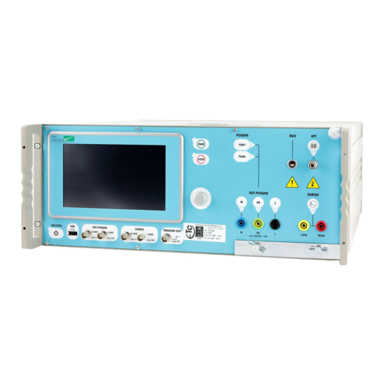
Page 37: Control Panel
General signals 4.1.1 Control part Control of the IMU4000 is carried out by internal computer. The computer controls the EMC tests, stores the inputs of the numeric input terminal, updates the graphic monitor, checks whether the inputs of the operators are valid values or not, stores the program and prepares test reports. The operator communicates with the IMU4000 via the graphic input terminal, the display and the soft keys. - Page 38 4.1.1.5 Push button ON/STBY (6) With this button, the IMU4000 will be set into the power ON / OFF mode. In the turn off mode, the control and the signals are deactivated. In Standby IMU4000, power consumption is at a minimum of 5 W.
-
Page 39: Operation Panel
IMU4000 4.1.1.9 Measuring outputs SURGE Voltage (11) and Current (12) During SURGE tests, voltage sequence of the SURGE waveform can be measured at the output socket (11) and the current sequence at output socket (12). The range and the accuracy of the measuring system is given in the Chapter 1.2 Technical data Section 1.2.8 measuring circuits, measuring outputs. - Page 40 Particularly for interference tests with high frequency components, such as EFT, a large surface earth connection is necessary. The earth terminal of the IMU4000 allows a low inductance earth connection between test equipment and the reference ground plane to be made.
-
Page 41: Rear Panel Of The Imu4000
4.2.1.2 Power supply of the IMU4000 (41) The IMU4000 receives its power via power connection (41). A power switch, a fuse and a filter are built in directly at the mains plug. Power consumption: turned “ON” minimum < 75VA; maximum power consumption < 150 W, standby < 1 W The fuse is rated with T 4A / 250 V. - Page 42 For external variac operation, the bridge (53) and (54) must be removed, see Chapter 6 „Testing with the IMU4000 D-V“. Supply data: min. 20 to max. 250 V a.c 16A Supply data: min.
- Page 43 A distance of about 20 cm must be maintained between the rear panel of the TRANSIENT 3000 and any wall, and about 3 cm between the sides of the IMU4000 and any equipment or wall. The IMU4000 can be built into a 19“ rack, with 3 cm side separation.
- Page 44 IMU4000 4.2.1.14 Trigger input (59) This input can be used for trigger the EMC pulses. The Tigger uses the negative slope of the Trigger signal. The trigger value at the input is approximately 5Vdc (active low). The +24V maximum input value is 24Vdc.
-
Page 45: Preparation For Operation
One half used for the EUT Power 1 connection on the rear side of the IMU4000 Generator, and the other half for supplying the EUT from the front panel. The high inrush current during the DIPS test can only be reached, when the public power supply can deliver 500 A peak current. - Page 46 10 Ohm and 9 µF is a load on the power supply. Solutions: 1. For testing with IMU4000 generator use a power supply without a fault current protective switch. 2. Connect an insulation transformer between power supply and IMU4000 Generator. One secondary output terminal of the transformer must be grounded.
-
Page 47: Eut Power With Voltages Different From The Public Power Line (Variac)
The external Variac replaces the internal Variac. Remove the two bridges. Power 1 EUT Power 1 (L1) of the IMU4000 must be connected with L1 of the external Variac. EUT Power 2 L, N, PE must be connected as shown on the picture. -
Page 48: Eut Power, Supply Of The Eut With Dc
2. Connect the DC power supply with EUT - Power 1 d.c inputs. Connect the positive pin of the dc source with + input and the negative pin with - input. The IMU4000 can be equipped with different extensions, which results in different operation modes described below:... -
Page 49: Surge Superimposing On Dc
IMU4000 5.4.1 SURGE superimposing on dc For this kind of test the dc voltage must be connected to input d.c EUT-Power 1 and the coupling path selected as in IEC 61000-4-5 ED3 defined. 49/104... -
Page 50: Hints For The Test Set Up According To Iec Standards
IMU4000 5.5 Hints for the test set up according to IEC standards We list below those experiences of EMC PARTNER which are important for the success of the various tests. This information is only partly given in the standards. Before a test is started, it is important to define which ports (inputs, outputs) must be tested. For the most... -
Page 51: Esd Test Set Up
IMU4000 5.5.2 ESD test set up Ports which must be tested: Enclosure Ports include operational keys, displays, ground and earth points, metallic parts such as connectors etc. Coupling path: Basically all types of coupling exist during static discharges. Practical experience shows that, for most electronic equipment, the current is the dominant parameter. -
Page 52: Test Set Up Surge
IMU4000 5.5.3 Test set up SURGE Ports which must be tested: AC/DC power supply, signal, data and I/O lines; earth connections Coupling path: Unlike the EFT and ESD tests stray capacitance are not important here. The frequencies contained in the SURGE impulses are lower. - Page 53 IMU4000 Test set up DIPS, Interruption Ports which must be tested: AC / DC power supply Störquelle Spannungsunterbrüche Coupling path: These disturbances appear on the power lines. Disturbance sources are short circuits between power lines, power line switching actions and heavy load changes etc.
-
Page 54: Test Set-Up For Table Top Equipment
Test set up Test sequence I. EFT Single Phase EUT 1. Connect the earth bar of the IMU4000 with the flat multiwire cable (1) to the reference ground plate HCP = Horizontal coupling plane ESD RP = Reference plane EFT 2. -
Page 55: Practical Testing Sequence
IMU4000 5.6 Practical testing sequence In practice, the following test procedures has been shown to be reliable: 1. Burst-Testing: Burst-testing on mains inputs with a test voltage of 4kV Burst-testing of signal and data lines up to 4kV The energy contained in the burst pulses is relatively small, thereby minimising damage to the test object. - Page 56 IMU4000 56/104...
-
Page 57: Testing With The Imu4000
6.1 Operation of the tester via touch screen monitor Only when Chapter 2 „Safety“ and Chapter 5 „Preparation for operation“ and all instructions have been followed the IMU4000 can be operated. To start the control, tester, the following steps must be carried out: ... - Page 58 IMU4000 By touching or clicking twice on Vnom the following windows will be shown Numerical input terminal for selecting the Level Vnom voltage level. selected The level can also be selected with the rotary knob beside the monitor. Actual selected submenu with o.k.
- Page 59 IMU4000 Another example of a conflict between the selected voltage and the repetition. Conflict the The repletion will repetion was too automatically be fast for the set to 12s for a selected Vnom voltage of 8000 12s is O.K. Conflict is in...
- Page 60 TRA Tester can be used. When the correct device (CDN) is selected the voltage of the IMU4000 will be Submenu limited coupling Sub menu coupling for CWG The listed coupling modes can be Green indicates selected the selected...
-
Page 61: The General Menu
IMU4000 6.2 The general menu General menus General menu pull down windows Touching a line will open an additional windows The parameters in the additional windows are valid for all tests 6.2.1 General menu “Setups” General menu pull down windows... -
Page 62: General Menu "Settings
The IMU4000 control can create a protocol and convert it into pdf or Csv files. The files can be stored onto the UBS stick and from the UBS stick the protocol can be printed from a PC. -
Page 63: General Menu "System
For running the interruption, voltage variation and DIPS, the EUT PWR1 Input on the rear side of the IMU4000 Generator must be connected to the mains. Please check that the L and N as written on the front panel correspond with the phase and neutral of the mains. -
Page 64: General Menu "Update
Depending on local safety standards, an emergency stop must be installed. All operators and laboratory personnel must be able to reach the emergency stop. On the rear side of the IMU4000 Generator there is an EMERGENCY STOP input. See Chapter 5 „Preparation for Operation“. -
Page 65: Example Cwg Operation
IMU4000 6.3.1 Example CWG operation Under consideration In RUN-mode, most of the parameters can be continuously varied using the „+“ and „- “ buttons. This is very helpful for exactly determining of the immunity level of the EUT. The manual change of the nominal voltage will be noted in the report with a warning. - Page 66 IMU4000 66/104...
-
Page 67: Maintenance And Servicing
After 15 minutes, the air filter must be dried before being reinstalled. If the DIPS and Variation circuit is used very often with high current, the VARIAC brushes must be changed. No further maintenance is necessary on the IMU4000. 7.2 Cleaning front and rearplate The cleaning of the front-, rear- and type plate can be made with warm soapy water and a cleaning tissues. -
Page 68: Esd
SURGE U-CRO for the voltage measurement at no load SURGE I-CRO for current measurement at short circuit (make a short circuit on the front panel of the IMU4000 using a banana plug type cable 1000 between L-N) 3. Setting measuring equipment Time base 5 µs,... -
Page 69: Calibration Of The Imu4000 By Emc Partner Ag
7.5 Calibration of the IMU4000 by EMC PARTNER AG EMC PARTNER calibrate every EXT-IMU4000 in accordance with the calibration chapter within the Basic Standards. Before a IMU4000 is delivered, calibrations are carried out in accordance with the basic documents. All data are within the tolerable tolerances. - Page 70 IMU4000 70/104...
-
Page 71: What Must Be Done Following Failed Operation
IMU4000-generator, or to correct an incorrect system configuration. 8.1 Service; Repairs The IMU4000 is a compact equipment for service the different EXT-TRA3000 or IMU4000 modules can be interchanged by the customer or by EMC PARTNER authorised service companies. List of EXT-TRA3000 for IMU4000 generators:... -
Page 72: Service Flowchart Of Imu4000 System
Step 1: Insert the USB stick Step 2: Select Service menu Step 3: Store the data on the USB stick Step 4: Send the data par email to EMC Partner 8.2 Spare parts list No spare parts are necessary for the IMU4000. 72/104... -
Page 73: Check Before You Contact The Service Of Emcp
IMU4000 8.3 Check before you contact the service of EMCP 8.3.1 Fuses Always check the fuses of the unit before you contact EMCP service. A set of fuses has been delivered with the tester. 8.4 Service department of EMC PARTNER AG... - Page 74 IMU4000 74/104...
-
Page 75: Packaging And Transport
If you transport the IMU4000 for outdoor EMC tests, the military box from EMC PARTNER is recommended. If you are transporting the IMU4000 to an EMC PARTNER field office for repair, attach a tag to the equipment showing the instrument owner and address, the name of the person to contact about the instrument, the instrument type and the serial number. - Page 76 TRANSIENT-2000 76/104...
-
Page 77: Recycling / Disposal
10 Recycling / Disposal 10.1 RoHS directive 2002/95/EG The IMU4000 generator complies with the directive 2002/95/EG (RoHS - Restriction of certain Hazardous Substances). From December 2005, all EMC Partner products either hand soldered or by machine are produced using lead-free solder. - Page 78 TRANSIENT-2000 78/104...
-
Page 79: Accessories
11 Accessories 11.1 TRA accessories to IMU4000 Versions Visit our Web site to get a complete overview about the accessories Selection of three phase CDN Type Short description 105114 CDN-A-06-32-AC-DC Automatic Coupling / Decoupling Network for SURGE and EFT Coupling onto 2 STRINGS DC+ and DC- up to 1000V and onto AC 3P/690V and 32A continuous. - Page 80 Accessories Type Short description 103477 CDN2000A-06-32 Three phase CDN with line voltages L to N/PE=280V and L to L=415V, line current 32A per phase. Automatic coupling path selection for EFT, SURGE and RING controlled by TRA2000, TRA2004, TRA2006, TRA3000 and MIG0603INx with SN > 199. 103695 CDN2000A-06-32 480V 3 phase CDN with line voltages L to N/PE=280V and L to L=480V, line current 32A per phase.
-
Page 81: Use Of Transient Accessories
For auto controlled accessories with a communication port, a box can be inserted into the communication line. When the setting of the ADAPTER BOX TRA-ACC corresponds with the connected accessories, automatically the IMU4000 will limit the output voltage to the rated voltage of the connected accessories. Short description... - Page 82 Accessories 11.2.2 Software: Firmware IMU4000 Press: Menu – System - Ext. Accessory – Change Accessories Select all EMC PARTNER accessories from the list When you press “Finish” you will see all EMC available in your laboratory. PARTNER accessories in the windows above.
-
Page 83: Remote Ports
12 Remote Ports 12.1 General 12.1.1 Ethernet port setting on IMU4000 The following steps must be carried out on IMU4000 to remote control from a local PC General menu pull down windows Touching a line will open an additional windows... -
Page 84: Using Web Browser
Connect with Ethernet cable type (crosswire) delivered with the IMU4000 standard accessories the PC to the IMU4000. When the TEMA3000 is installed on the PC, then the IMU4000 can be remote controlled from the PC. 12.1.3 Using Web Browser For Web server access, start your web browser (internet explorer, Morzilla, Firefox,…) and write the IMU4000 IP address. - Page 85 EMC PARTNER AG TEMA3000 includes Generator and remote control The TEMA3000 setting is identical to the IMU4000 setting on the touch screen. 85/104...
- Page 86 Remote Ports Detailed information can be obtained from the help file of TEMA3000 Software. 86/104...
-
Page 87: Appendix And Corrections
3. The time to half value must be between 35 and 65 ns. 4. The source impedance of the tester is 50 Ohm, providing the coefficient of UL/Uout =2. = charging voltage Uout = output voltage into 50 Ohm E-IMU4000-E-Manual 87/104... -
Page 88: Definition Of The Esd Waveform
Appendix and Corrections 13.1.2 Definition of the ESD Waveform IEC 61000-4-2 Ed.2 Level Test Peak Amplitude Amplitude Current peak voltage current kV+-5% A+-15% 30ns 60 ns A+-30% A+-30% 22,5 It is only possible to check the impulse current by using very expensive measuring equipment. The price of such an instrument today lies at approx. -
Page 89: Definition Of The Surge Waveform
20µs±20% Current at short circuit Strom im Kurzschluss With this information the SURGE circuit of the IMU4000 can be easily verified. Example: "Voltage" - choose 1 kV charging voltage - measure the no load voltage at the generator output. Check whether the wave-form is within the tolerances or not. -
Page 90: Dips Specification
Appendix and Corrections Spannungsunterbrüche in IEC 1000-4-11, EN 61000-4-11 13.1.4 DIPS Specification Test levels DIPS Prüflevel : Spannungsunterbrüche Test Level Voltage Duration % U T Dip/int (in period) % U T 0.5* Test Level 70% Dip 30% In addition to the data showed in the figure, such as test levels, duration of the interruption, transition time, etc., the inrush current must be tested. -
Page 91: Variation Specification Iec 61000-4-11
EMC PARTNER AG Spannungsschwankungen in IEC 1000-4-11 und EN 61000-4-11 13.1.5 VARIATION Specification IEC 61000-4-11 Ed.1 Prüflevel : Spannungsvariation Test levels Voltage variation VoltageTest Time for Time at Time for Level decreasing reduced increasing Voltage voltage voltage 40 % U T 2 s ... -
Page 92: Variation Specification Iec 61000-4-11 Ed.2
Appendix and Corrections 13.1.6 VARIATION Specification IEC 61000-4-11 Ed.2 92/104... -
Page 93: Correction
EMC PARTNER AG 13.2 Correction 13.2.1 Declaration of conformity to the EMC directive 2004/108/EC See appendix at the end of this documents. 13.2.2 Declaration of conformity to the LV directive 2006/95/EC See appendix at the end of this documents. 13.2.3 Declaration of conformity to the Basic Standards See appendix at the end of this documents. - Page 94 Appendix and Corrections 94/104...
-
Page 95: Glossary
As produced by lightning and switching of power lines. Short voltage interruption or short voltage drop International standardisation organisation for electronic technology VARIAC Voltage variable transformer SPIKE One pulse of the burst oscilloscope High Voltage rms. root mean square; effective value E-IMU4000-E-Manual 95/104... - Page 96 Glossary Used symbols: Direct current Alternating current Three phase alternating current Earth (ground) terminal Protective conductor terminal IEC 417, No. 5019 Caution, risk of electric shock ISO 3864, No. B.3.6 Caution (refer to accompanying documents) ISO 3864, No. B.3.1 96/104...
-
Page 97: Index
Quick verification by the user source Numeric control panel (18) Technical data EFT Run Mode Electromagnetic Compatibility Emergency Stop 42, 45, 66 Operational Conditions Run Mode source Tecnical data ESD characteristics Ethernet Packaging and shipment Remote control Pause Ethernet port personal safety E-IMU4000-E-Manual 97/104... - Page 98 Index Power EUT (24) SURGE Measuring outputs Power line voltage, power consumption Symbols Power supply of the IMU4000 Push button ON/STBY (6) Test test set-up for table top equipment Recycling/Disposal touch screen information Run (5) Trigger input Run (8) Trigger output for oscilloscope (13)
- Page 99 Declaration of Conformity to Standards The EMC Tester Type: IMU4000 Complies with the following standards: IEC/EN 61000-4-4 Ed.3 IEC/EN 61000-4-2 Ed.2 a.c. MF IEC/EN 61000-4-8 Ed.2 with antenna Surge MF IEC/EN 61000-4-9 Ed.1 with antenna DIPS and INTERRUPTION on a.c. power IEC/EN 61000-4-11 Ed.2 single phase...
- Page 100 Index 100/104...
- Page 101 Manufacturer Declaration Of Conformity LV Directive 2006/95/EC; The EMC Tester Type: IMU4000 is designed and manufactured complying with the following harmonised standards: Harmonised: EN 61010-1: 2010 international IEC 61010-1: 2010 in accordance with the regulation of LV - directive of the members states 2006/95/EC...
- Page 102 Index 102/104...
- Page 103 Manufacturer Declaration Of Conformity EMC Directive 2004/108/EC The EMC Tester Type: IMU4000 has been tested in accordance with the following standards: harmonised: EN 61000-6-3: 2007 EN 61326: 2006 international IEC 61000-6-3 IEC 61326-1 Fulfilling the directions of the EMC - Directive 2004/108/EC...
- Page 104 Index 104/104...
Need help?
Do you have a question about the IMU4000 and is the answer not in the manual?
Questions and answers