
Related Manuals for EMC-PARTNER AVI3000


Summary of Contents for EMC-PARTNER AVI3000
- Page 1 LARGEST RANGE OF IMPULSE TESTERS UP TO 100KV/100KA User Manual Version 1.0 AVI3000 CN-BT7 SHUNT0E1 CN-GI-CI-V...
- Page 2 Fax +41 775 20 59 service@emc-partner.ch Your local representative Check www.emc-partner.ch to find your local representative The small print All products from EMC PARTNER AG fulfill the EMC and safety requirements to obtain CE certification. A copy of the individual certificates can be viewed and downloaded from www.emc-partner.com section company documents.
- Page 3 Safety instructions This warning sign is visible on the tester. Meaning: This equipment should only be operated by trained personnel after carefully reading the user manual. The system belongs to Safety class 1 The system fulfills the requirements of the safety standards IEC 61010 for laboratory measurements equipment "Safety requirements for electrical measuring, control and laboratory equipment".
- Page 4 Sicherheitshinweise Gefahr! Dieses Warnsysmbol ist am Tester sichtbar angebracht. Es bedeutet: Diese Ausrüstung darf nur durch ausgebildetes Personal bedient werden, nachdem diese die Bedienungsanleitung sorgfältig gelesen hat. Das Gerät gehört der Schutzklasse I an. Das Gerät erfüllt die Anforderungen der Sicherheitsnormen IEC 61010 für Messungen in Laboratorien “Sicherheitsanforderungen an elektrische Mess- und Regelgeräte sowie Laborausrüstung”.
- Page 5 Consignes de sécurité Ce sigle d’avertissement est visible sur le testeur. Signification: Cet équipement ne doit être utilisé que par du personnel formé et après avoir soigneusement lu le mode d’emploi. Le système appartient à la classe de sécurité 1 Le système répond aux exigences des normes de sécurité...
-
Page 6: Table Of Contents
Contents Contents 1 System overview 2 Initial Operation 2.1 Unpacking and Checking ........10 2.2 Installation . - Page 7 Contents 9.2 Maintenance ......... 34 9.3 Cleaning .
-
Page 8: System Overview
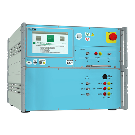
1 System overview AVI3000 (PN 107630) AVI3000 generator is a compact system with all waveforms for DO-160 section 22 up to level 3 and MIL-STD-461 CS117 for internal tests. A coupling transformer, for cable injection tests, completes the system. The 7 inch graphic colour touch panel provides an intuitive and comfortable user interface. - Page 9 1 System overview The preferred coupling method for WF4 is Ground Injection. Ground Injection is possible directly with AVI3000 without any additional coupling device. The CN-GI-CI-V is only neccessary if WF4 will be applied as Cable Induction test. Not all accessories are used for all tests. The chapter “Perform a test” provides more informa- tion.
-
Page 10: Initial Operation
2 Initial Operation 2 Initial Operation 2.1 Unpacking and Checking 1. Check the packaging for signs of damage. If damage is visible, report this to the shipping company immediately. 2. Gently remove the equipment from the packaging. 3. Check the delivery for completeness using the delivery note and the accessory lists for the var- ious items. -
Page 11: Using The Generator
3 Using the Generator 3 Using the Generator 3.1 Front panel 1 ON/STBY Power-up or power-down the generator. 2 Touchscreen monitor User interface to perform all functions including test types selection, parameter entry, saving and recalling tests. 3 Rotary knob Entry device enables faster navigation and parameter entry. - Page 12 5V EUT power state 9 Plug-in module The plug-in contains all WF3 circuits. It is part of the AVI3000 standard delivery. Future plug-ins could be developed for different wave forms. The plug-ins are secured by two retained screws on the bottom.
-
Page 13: Rear Panel
3 Using the Generator 3.2 Rear panel 1 AC Socket / Main fuse A country specific mains cable is delivered with the equipment, this should be used to connect to the mains power supply. A mains fuse is located in the socket housing. The value is indicated on the equipment type plate. -
Page 14: Software User Interface
3 Using the Generator The green lamp indicates safety circuit open, no test can be started The red lamp indicates safety circuit closed, tests can be started 3 EUT Power Input Separate EUT Power input if required for a specific plug-in. 4 RS485 Interfaces Interfaces to connect additional equipment that is controlled directly from the test equipment. - Page 15 3 Using the Generator is not currently available. Select a test by bringing the relevant icon to centre screen. This is achieved by finger swipe on the touch panel or by using the rotary knob. Not all tests are available all the time. Availability depends on hardware configuration. To simplify the menu structure, tests that are unavailable can be removed from the configuration.
-
Page 16: Perform A Test
4 Perform a test 4 Perform a test Additional information for calibration is also available in the calibration report. 4.1 Programming the generator The same process is used to program the generator for different tests. In the first step, the parameters should be set according to the requirement of the test. -
Page 17: Run A Test
4 Perform a test For each parameter, an additional help text ist provided directly on the generator. Press and hold a parameter to open the help text in a popup window. 3 Parameter image Individual images clarify the effect of each parameter. 4.2 Run a test Starting a test by pressing the run button on the front panel, changes the display to the run view. -
Page 18: Pin Injection Wf3 / Wf4 / Wf5A
4.3.1 System Calibration Prior to each test, the system has to be calibrated. The calibration is made using the 2m cable on the AVI3000 at the desired test level with both polarities. 1 Generator Select the desired Waveform and Pin Injection as coupling type. -
Page 19: Eut-Test
4 Perform a test 4 Oscilloscope The oscilloscope must have a minimum bandwith of 500 MHz. 4.3.2 EUT-Test 1 Generator Select the desired Waveform and Pin Injection as coupling type. For all Pin Tests, the necessary decoupling elements are already built into the generator. 2 Connection cable The 2m MC-cable is connected between the EUT and the generator output. -
Page 20: Cable Bundle Wf1, Wf2, Wf3, Wf5A, Wf6
4 Perform a test 4.4 Cable Bundle WF1, WF2, WF3, WF5A, WF6 4.4.1 Calibration Prior to each test, the system has to be calibrated. The calibration is made at the desired test level with both polarities. 1 Generator Select the desired Waveform and Cable Induction. The correct output is always indicated with a red LED. -
Page 21: Eut-Test
4 Perform a test For WF6, connect the WF6-output on the generator with the CN-BT7 INPUT 1 using a 2 m HV-BNC cable. On the coupler, put the MC-bridge in the FILTER position. 3 Measurement Equipment Use a HV differential probe to measure the open circuit voltage on MONITOR 1. For the current measurement, different setups are used. -
Page 22: Ground Injection Wf4
4 Perform a test 1 Generator Select the desired Waveform. The correct output is always indicated with a red LED. The connection setup for SingleStroke, MultipleStroke and MultipleBurst is the same. The desired mode has to be selected in the generator menu. 2 CN-BT7 The output of the generator is connected with the input of the CN-BT7. - Page 23 4 Perform a test 1 Generator Select the desired Waveform and Ground Injection as coupling type. 2 Connection cable The calibration is performed including a 2m MC-cable. Connect the cable to the correct output. The correct output is always indicated by a red LED. 3 Measurement Equipment Use a HV differential probe to measure the open circuit voltage.
-
Page 24: Eut-Test
4.6 Cable Induction WF4 The preferred coupling method for WF4 is Ground Injection. Ground Injection is possible directly with AVI3000 without any additional coupling device. The CN-GI-CI-V is only neccessary if WF4 will be applied as Cable Induction test. 4.6.1 System Calibration Prior to each test, the system has to be calibrated. - Page 25 4 Perform a test 1 Generator Select WF4 Cable Induction with the CN-GI-CI-V as Coupling Device. The correct output is indi- cated with a red LED. The connection setup for SingleStroke and MultipleStroke is the same. The desired mode has to be selected in the generator menu. 2 CN-GI-CI-V The output of the generator is connected with a 2m MC-cable to the 5 Turn input of the CN-GI- CI-V.
-
Page 26: Eut-Test
4 Perform a test 4.6.2 EUT-Test 1 Generator Select WF4 Cable Induction with the CN-GI-CI-V as Coupling Device. The correct output is indicated with a red LED. 2 CN-GI-CI-V The output of the generator is connected with a 2m MC cable to the 5 Turn input of the CN-GI- CI-V. -
Page 27: Additional Software Features
5 Additional Software Features 5 Additional Software Features 5.1 Protocols Select (General Menu) –> Protocols A protocol containing test parameters and results can be saved in the equipment. Additional information about the EUT and environment conditions can be added. 1 Last Protocol Shows a preview of the latest protocol, even if Create Protocol is not selected. -
Page 28: Store Setup
5 Additional Software Features The EMCP Library is read only. It is possible to copy a test from the library to the user space and edit the copy. 5.2.1 Store setup 1 Create new setup Configure a test setup in a new window. The current test in the generator will not be changed. 2 Save current setup The currently configured test will be saved. -
Page 29: File Manager
5 Additional Software Features 2 Edit the setup Click on a setup to edit, modify or delete from the list. Setups are stored as a copy in the setup linker. Any change to parameters does not affect the source file in the library. 3 Change order Use the up and down arrows to move a setup position in the sequence. -
Page 30: Configuration
6 Configuration 6 Configuration 6.1 Settings Select (General Menu) –> Settings 1 Audio Volume and type of the different audio messages 2 Localisation Set equipment time and date and the required format. This information will be included in the test report and file data. The user interface is available in different languages. -
Page 31: Generator
6 Configuration Risk of network errors Connection errors can affect the entire network. If the network does not support DHCP, or dynamic TCP/IP configuration is disabled, assign a valid address information before connecting the equipment to the LAN. Contact the local network administrator to obtain a valid IP address. -
Page 32: Accessories
V-PROBE-SI Differential HV-Probe up to 7kV with a bandwidth up to 70MHz to measure all Waveforms of AVI3000 during calibration and test. I-PROBE-MB-P1 Clamp on current monitor probe for maximum 5cm cable diameter and a bandwith up to 15MHz. -
Page 33: Remote Operation
Easy to use test library with hundreds of tests Seamless integration of your DSO Get in touch with your local representative or directly with EMC PARTNER for more information about TEMA3000. Go to www.emc-partner.com for a free software demo version. Page 33/45... -
Page 34: Maintenance And Service
Update via USB You can also download the newest version from www.emc-partner.com. Store the update file on a USB-Stick and transfer into the equipment via the USB port on the front panel.The update process starts automatically. -
Page 35: Customer Service
Plug in a USB stick Select (General Menu) –> Generator In the tab Help select Copy to USB The information is transferred to the root folder of the USB. Send file by e-mail to service@emc-partner.ch Page 35/45... -
Page 36: Technical Data
461G CS117 internal (whichever is higher) in the defined calibration setup (open circuit or short circuit). AVI3000 can reach the test level or the corresponding limit level with every kind of load. To fullfill this condition, the programable levels are higher than needed during calibration. -
Page 37: Wf1 Cable Induction
10 Technical Data 10.2 WF1 Cable Induction Standard DO-160 Section 22 MIL-STD-461G CS117 Coupling Type Cable Induction Level Single Stroke 25A - 900A Multiple Stroke 25A - 900A First Stroke 20A - 300A Subsequent Strokes Current Risetime 6.4us Duration 69us Voltage Risetime <6.4us... -
Page 38: Wf3 1Mhz Pin Injection
10 Technical Data 10.4 WF3 1MHz Pin Injection Standard DO-160 Section 22 Voltage 100V - 700V +10% / -0% Current 4A - 28A +10% / -0% Impedance 25Ohm Voltage Frequency 1MHz Damping 25% - 75% First Peak to Fifth Peak Current Frequency 1MHz... -
Page 39: Wf3 10Mhz Cable Induction
10 Technical Data 10.6 WF3 10MHz Cable Induction Standard DO-160 Section 22 MIL-STD-461G CS117 Level Single Stroke 50V - 1100V Multiple Stroke 50V - 1100V First Stroke 50V - 1100V Subsequent Strokes Multiple Burst 50V - 800V Voltage Frequency 1MHz Damping 25% - 75% First Peak to Fifth Peak... -
Page 40: Wf4 Ground Injection
10 Technical Data 10.8 WF4 Ground Injection Standard DO-160 Section 22 Level Single Stroke 10V - 1600V Multiple Stroke 10V - 800V First Stroke 10V - 400V Subsequent Strokes Voltage Risetime 6.4us Duration 69us Current Risetime <6.4us Duration >69us Bypass Current max. -
Page 41: Wf5A Pin Injection
10 Technical Data 10.10 WF5A Pin Injection Standard DO-160 Section 22 Voltage 50V - 500V +10% / -0% Current 50A - 500A +10% / -0% Impedance 1Ohm Current Risetime 40us Duration 120us Voltage Risetime 40us Duration 120us Syncro positive Pulse negative Pulse max. -
Page 42: Wf6
10 Technical Data 10.12 WF6 Standard DO-160 Section 22 MIL-STD-461G CS117 Coupling Type Cable Induction Level Multiple Burst 2.5A - 75A Current Risetime 250ns Duration Coupling Device CN-BT7 10.13 Multiple Stroke Timing DO160 Pattern Pulses 1 First transient 14 Subsequent Transients Duration <1.5s Spacing... -
Page 43: Avi3000
10 Technical Data 10.15 AVI3000 Input Power Voltage 100V - 240V Frequency 50Hz - 60Hz Current max. 4A Consumption Switched off Standby <15VA Test running max. 400VA Dimensions 60cm x 45cm x 37cm l x h x w Weight 50kg... -
Page 44: Cn-Gi-Ci-V
10 Technical Data 10.17 CN-GI-CI-V max. EUT Current WF4 @ 800Hz WF4 @ 400Hz WF4 @ 50/60Hz Turn-Ratio up to Level 3 up to Level 2 Dimension 65cm x 53cm x 50cm l x h x w Aperture 6cm x 12cm Weight 190kg 10.18 SHUNT0E1... -
Page 45: Appendix
11 Appendix 11 Appendix 11.1 Recycling / Disposal RoHS directive 2011/65/EU The system complies with the directive 2011/65/EU (RoHS - Restriction of certain Hazardous Substances). From December 2005, all EMC PARTNER products either hand soldered or by machine are produced using lead-free solder. WEEE directive 2012/19/EU The system is exempted from the directive 2012/19/EU (WEEE) under category 9.
Need help?
Do you have a question about the AVI3000 and is the answer not in the manual?
Questions and answers