
Related Manuals for ABB IRB6400


Summary of Contents for ABB IRB6400
- Page 1 MECHANICAL DISASSEMBLY/ASSEMBLY GUIDELINES IRB6400 INDUSTRIAL ROBOT Manual Part #7000695-001 Flexible Automation Inc. 1250 Brown Road Auburn Hills, Mich. 48326 1-800-451-6268 Effective Date: June 1, 1996...
- Page 2 Table of Contents Table of Contents Table of Contents INTRODUCTION How to use this Manual What you must know to use the Robot Robot Components Robot Identification Symbols used in this Manual SAFETY Important General Safety Safety Features Safety Guidelines Safety During Maintenance Safety During Programming Safety Control Chain of Operation...
- Page 3 Table of Contents Table of Contents (Cont) Table of Contents (Cont) AXIS 1 GUIDELINES Motor Removal, Installation Gear Reduction Unit Removal, Installation Bearing Removal, Installation AXIS 2 & 3 GUIDELINES Motors Removal, Installation Gear Reduction Units Removal, Installation Balance Cylinders Removal, Installation Parallel Bar Removal, Installation Bearings Removal, Installation Lower, Parallel Arm Removal, Installation...
- Page 4 Table of Contents Table of Contents (Cont) Table of Contents (Cont) ROBOT CALIBRATION General Calibration Procedure Setting Marks on Robot Checking Calibration Procedure Alternative Calibration Procedure Calibration Equipment PARTS LISTS & ILLUSTRATIONS Base (B) Shoulder (S) Lower Arm (L) Upper Arm (U) Wrist (W) Face (F) Shoulder - Shelf Mounted (SM)
- Page 5 SECTION 1 Introduction Disassembly/Assembly Guidelines IRB 6400...
- Page 6 Introduction INTRODUCTION Table of Contents Page Subject 1 - 1 How to Use This Manual 1 - 5 What You Must Know to Use the Robo t 1 - 6 Robot Components 1 - 7 Robot Identification 1 - 8 Symbols Used in this Manual Disassembly/Assembly Guidelines...
- Page 7 In addition, a tool list is presented listing the tools and ABB part numbers that aid in disassembly, assembly, and maint e- nance procedures. Section 5 - AXIS 1 DISASSEMBLY/ASSEMBLY GUIDELINE S Section 5 contains the outlines you can use as guidelines when you disasse m- ble and assemble components associated with the robot’s Axis 1.
- Page 8 Introduction Section 6 - AXES 2 & 3 DISASSEMBLY/ASSEMBL Y GUIDELINES Section 6 contains the outlines you can use as guidelines when you disasse m- ble and assemble components associated with the robot’s Axes 2 & 3. These outlines are presented in a clear, step by step format. Each part involved in a procedure is identified by a number that is in a list and on an exploded illustr a- tion.
- Page 9 The illustrations are in exploded format for ease in reading how parts relate to each other. The parts lists show the part name and ABB part number, quantity, and exploded illustration reference number. The following assemblies are contained in this...
- Page 10 Introduction Section 14 - REFERENCE CABLE LAYOUT S Section 14 contains electrical cables reference layouts that you can refer to for added clarification of component relationship. The layouts are actual copies of working drawings and have reference numbers that DO NOT refer to reference numbers in the disassembly and assembly guidelines.
-
Page 11: What You Must Know To Use The Robot
Introduction WHAT YOU MUST KNOW TO USE THE ROBOT Normal maintenance and repair work usually requires just standard tools . Some repairs, however, do require specific tools. These repairs and the type of tool required, where needed, are described in more detail . The power supply must always be switched off whenever work is carried out. -
Page 12: Robot Components
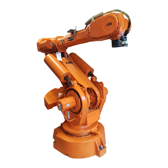
Introduction ROBOT COMPONENTS The major components as referred throughout this manual are shown in the below illustration. Note that the left side of the robot is on your left side if you were standing behind and facing. In short, the robot’s left side is the same as your left side. -
Page 13: Robot Identification
S4/M94A program Program N o3HAB XXXX-X Boot Dis k1 (2) Serial N o IRB 6400-XXX X Property of ABB Västerås/Sweden.All rights reserved. Reproduction, modification, use or disclosure to third parties without express authority is strictly forbidden. Copyright 1993. Authorized to be used in the controllers with the above stated serial. -
Page 14: Symbols Used In This Manual
Introduction SYMBOLS USED IN THIS MANUAL The symbols used throughout this manual are as follows : EMERGENCY This symbol warns you of dangers that can result in physical injury if great care is not followed. CAUTION This symbol warns you of conditions that can result in damage to equipment if care is not followed. - Page 15 SECTION 2 Safety Disassembly/Assembly Guidelines IRB 6400...
-
Page 16: Table Of Contents
Safety SAFETY Table of Contents Page Subject 2 - 1 Important 2 - 2 General Safety 2 - 3 Safety Features 2 - 4 Safety Guidelines 2 - 5 Safety During Maintenance 2 - 6 Safety During Programming 2 - 7 Safety Control Chain of Operation 2 - 8 Risks Associated with Live Parts... - Page 17 ABB has supplied the robot with numerous interfaces for external safety equi p- ment. It is highly suggested that any place a safety device can be connected, should be. ABB is not responsible for the lack of external safety devices or any concerns if the external safety devices are manually bypassed.
-
Page 18: General Safety
Safety GENERAL SAFETY The user of an ABB robotic system has the final responsibility for the safety of personnel working with the system. The safety procedures used should be a p- propriate to the level of danger and risk associated with the particular install a- tion. -
Page 19: Safety Features
Safety SAFETY FEATURES Selection of Operating Mod e The robot can be operated either manually or automatically. In Manual mode, the robot can only be operated using the teach pendant, not by any external equipment. Reduced Speed The speed can be limited to a maximum of 250 mm/s. A speed limitation applies not only to the Tool Center Point (TCP), but to all parts of the robot. -
Page 20: Safety Guidelines
Safety SAFETY GUIDELINES When working with any robot system, observe the following safety guidelines: Keep the operator work area clean at all times. Know the location of all EMERGENCY STOP buttons and POWER ON/ OFF switches that may have to be used quickly . Make sure that each person directly responsible for the operation of the r o- bot system has a thorough knowledge of all safety procedures and pra c- tices. -
Page 21: Safety During Maintenance
Safety SAFETY DURING MAINTENANCE When performing maintenance on the robot system, all of the previous safety guidelines should be in effect as well as the following: Make sure that all persons within the work envelope are thoroughly fami l- iar with the performance characteristics of the robot and its potential ha z- ards. -
Page 22: Safety During Programming
Safety SAFETY DURING PROGRAMMING When programming the robot, all of the above safety guidelines should be in effect as well as the following: The robot system must be under the sole control of the programmer . Only the programmer is allowed in the restricted work envelope . Movement of equipment into the work envelope must be under the sole control of the programmer. -
Page 23: Safety Control Chain Of Operation
Safety SAFETY CONTROL CHAIN OF OPERATION The safety control order of operation is based on dual electrical safety circuits (Run Chains) which interact with the robot computer and enable the MOTORS ON mode. The electrical safety circuits consist of several switches connected in series so that ALL of them must be closed before the robot can be set to MOTORS ON mode. -
Page 24: Risks Associated With Live Parts
Safety RISKS ASSOCIATED WITH LIVE PARTS Controller A danger of high voltage is associated with the following parts : The mains supply/mains switch The power unit The power supply unit for the computer system (220 V AC) . The rectifier unit (240 V AC and 340 V DC. Especially Capacitors!). The drive unit (340 V DC). - Page 25 LIMITATION OF LIABILITY The previous information regarding safety must not be construed as a warranty by ABB Flexible Automation that the industrial robot will not cause injury or damage even if all safety instructions have been complied with . Related Information...
- Page 26 SECTION 3 Robot Handling Disassembly/Assembly Guidelines IRB 6400...
- Page 27 Robot Handling ROBOT HANDLING Table of Contents Page Subject 3 - 1 Robot Lifting 3 - 2 Crane Lifting Robots 3 - 3 Fork Lifting Robots 3 - 4 Crane & Fork Lifting S/2.9-120 Robot s 3 - 4 Fork Lifting PE/2.25-75 Robots 3 - 5 Releasing Axes Brakes Manually 3 - 6...
-
Page 28: Robot Lifting
Robot Handling ROBOT LIFTING The best way to lift the manipulator is to use lifting straps and a traverse crane. Attach the straps to the lifting eyes on both sides of the frame (see Figure 1). The lifting straps dimensions must comply with the applicable standards for lif t- ing. - Page 29 Robot Handling Crane lift , in calibation position for models: 2.4-120, 2.4-150, 2.8-120 and 3.0-7 5 Lifting wires must go between the upper arm and motor of axis 4 Figure 2 Lifting the manipulator with the arm system in the calibration position. Disassembly/Assembly Page 3- 2 Guidelines...
- Page 30 Robot Handling Fork lift for models: 2.4-120, 2.4-150, 2.8-120 and 3.0-7 5 1050 1120 *) *) valid for Lift position 2.4-150, 2.8-120, Version 3.0-75 2.4-120 2.4-150 2.8-120 1350 3.0-75 1350 Figure 3 Lifting the manipulator using a fork lift. WARNING! CRANE LIFT IS NOT ALLOWED WITH FORK LIFT ARRANGEMENT! Disassembly/Assembly Page 3- 3...
- Page 31 Robot Handling WARNING! FORK LIFT BRACKET MUST BE REMOVED BE- FORE ROBOT IS OPERATED! Fork lift for: Crane lift for: S /2.9-120 S /2.9-120 Figure 4 Lifting the manipulator using a crane or a fork lift. Fork lift for: PE /2.25-75 Figure 5 Lifting the manipulator using a fork lift.
-
Page 32: Releasing Axes Brakes Manually
Robot Handling RELEASING AXES BRAKES MANUALLY All axes come equipped with holding brakes. If the position of the manipulator axes are to be changed without connecting the controller, an external voltage supply (24 V DC) must be connected to enable releasing of the brakes. The voltage supply should be connected to the contact at the base of the manip u- lator (see Figure 6). -
Page 33: Restricting Axes Movement Mechanicall Y
Robot Handling RESTRICTING AXES MOVEMENT MECHANICALL Y When installing the manipulator, make sure that it can move freely within its e n- tire working space. If there is a risk that it may collide with other objects, its working space should be limited, both mechanically and using software. Insta l- lation of an optional extra stop for the main axes 1, 2 and 3 is described belo w Limiting the working space using software is described in the System Para m- eters in the User’s Guide. - Page 34 SECTION 4 Maintenance Disassembly/Assembly Guidelines IRB 6400...
-
Page 35: Axis
Maintenance MAINTENANCE Table of Contents Page Subject 4 - 1 General Maintenance 4 - 2 Maintenance Schedule 4 - 3 Maintenance Instructions 4 - 3 General Instructions 4 - 4 Lubricating Axis 1 Large Bearing (S46) 4 - 5 Lubricating Axis 1 Gear Reduction Unit (S59) 4 - 6 Lubricating Axes 2 &... -
Page 36: General Maintenance
Maintenance GENERAL MAINTENANCE The robot is designed to be able to work under very demanding conditions with a minimum of maintenance. Nevertheless, certain routine checks and preve n- tative maintenance must be carried out at specified periodic intervals. • The exterior of the robot should be cleaned as required. Use a vacuum cleaner or wipe it with a cloth. -
Page 37: Maintenance Schedule
Maintenance MAINTENANCE SCHEDULE MAINTENANCE INTERVALS CHECK PRESCRIBED ONCE 4000 HRS 6000 HRS MAINTENANCE PAGE 5 YEARS YEAR 2 YEARS 3 YEARS Cabling Mechanical Stop Axis 1 Oil Level in Gear 4 & 5 Cooling Motor Axis 1 FILTER CHANGING Large Diameter Bearing GREASING Gearbox Axis 1 ROBOT... -
Page 38: Maintenance Instructions
Maintenance MAINTENANCE INSTRUCTIONS General Instructions Check regularly: • for any oil leaks. If a major oil leak is discovered, call for service personnel . • for excessive play in gears. If play develops, call for service personnel . • that the cabling between the control cabinet and robot is not damaged . Cleaning: Clean the robot exterior with a cloth when necessary. -
Page 39: Lubricating Axis 1 Large Bearing (S46)
Continue greasing until new grease exudes from the rubber seal (2) . • Remove excess grease with a cloth. Type of grease: ABB art. no. 1171 4013-301, quality 7 1401-30 1 ESSO Beacon EP 2 Shell Alvanina EP Grease SKF Grease LGEP 2... -
Page 40: Lubricating Axis 1 Gear Reduction Unit (S59)
Volume: 1.3 litres (0.36 US gallon). About 3.0 litres (0.82 US gallon) should be used when changing the grease. Type of grease: ABB 3HAA 1001-294 Optimol Longtime PD 0 Tools: See Tool list, page 4-25. Disassembly/Assembly Page 4 - 5... -
Page 41: Lubricating Axes 2 & 3 Gear Units (S35)
1.3 litres (0.36 US gallon). About 2.0 litres (0.82 US gallon) should be used when changing the grease. Type of grease: ABB 3HAA 1001-294 Optimol Longtime PD 0 Tools: See Tools List, page 4-25. CAUTION: IT IS IMPORTANT THAT THE DRAIN PLUG IS RE- MOVED DURING LURICATION. -
Page 42: Oil Change Gearbox, Axis 4 (U61)
Maintenance Oil Change Gearbox, Axis 4 (U61 ) • Move the upper arm to the horizontal position . • Remove the plugs (A) and (B). • Drain off the old oil through the hole (A). See figure below . • Clean the magnetic drain plug before refitting . - Page 43 Maintenance Type of oil: ABB 1171 2016-604 Equivalents: BP Energol GR-XP 320 Castrol Alpha SP 320 Esso Spartan EP 320 Klüber Lamora 320 Mobil Mobilgear 632 Optimol Optigear 5180 Shell Omala Oil 320 Texaco Meropa 320 Disassembly/Assembly Page 4 - 8...
-
Page 44: Oil Change For Axis 5 Gearbox (W8)
Maintenance Oil Change for Axis 5 Gearbox (W8 ) Move the upper arm to the horizontal position with axis 4 turned +9 0 o . • • Open the oil plug 1, and then oil plug 2 so that air can enter . •... - Page 45 Maintenance Type of oil: ABB 1171 2016-604 Equivalents: Energol GR-XP 320 Castrol Alpha SP 320 Esso Spartan EP 320 Klüber Lamora 320 Mobil Mobilgear 632 Optimol Optigear 5180 Shell Omala Oil 320 Texaco Meropa 320 Disassembly/Assembly Page 4 - 10...
-
Page 46: Lubricating Axis 6 Gearbox (F17)
. Volume: 0.25 litres (0.07 US gallon). About 0.4 litres (0.11 US gallon) should be used when changing the grease. Type of grease: • ABB 3HAA 1001-294 Optimol Longtime PD 0 Guide hole Disassembly/Assembly Page 4 - 11 Guidelines... -
Page 47: Checking Axis 1 Mechanical Stop
Maintenance Checking Axis 1 Mechanical Sto p Check regularly as follows : Stop pin: • that the rubber cover is not damaged. • that the stop pin can move in both directions . • that the stop pin is not bent. Adjustable stop arms: •... -
Page 48: Changing Measuring System Battery
Maintenance Changing Measuring System Batter y The battery to be replaced is located in the control cabinet, under the cover, in the front of the frame. The article number of the battery is 4944 026-4 . Type: Rechargeable Nickel-Cadmium battery. The battery must never be thrown away, it must always be handled as hazar d- ous waste. -
Page 49: Changing Axis 1 Cooling Filter
Maintenance Changing Axis 1 Cooling Filte r • Loosen the filter holder at the intake and remove filter . • Insert the new filter and replace the filter holder . The article number of the filter is 3HAA 1001-612 . FILTER Disassembly/Assembly Page 4 - 14... -
Page 50: Changing Control Air Conditioner Filter
Maintenance Changing Control Air Conditioner Filte r • Remove the grating on the left side of the refrigerating machine . • Remove the old filter and insert a new one. • Replace the grating. • The article number of the filter is 7820 004-3 . Disassembly/Assembly Page 4 - 15 Guidelines... -
Page 51: Changing Control Memory Battery Backup
Maintenance Changing Control Memory Battery Backu p Type: Lithium Battery. The article number of the battery is 4944 026- 5 The batteries (two) are located on the right side of the computer rack (see Fig- ure 12). WARNING! Do not charge the batteries! An explosion could re- sult or the cells could overheat. -
Page 52: Adjusting Axis 4 Gear Play
Maintenance ADJUSTMENTS Adjusting Axis 4 Gear Play The following conditions are to exist before play is adjusted : REFERENCE DRAWINGS Exploded View: 1. Oil for axis 4 (U83) gearbox is removed. “U” (pg 12-4) 2. Axis 4 (U83) motor is removed. Assemblies: 3. -
Page 53: Adjusting Play Between Axis 4 Motor Pinion
Axis 5 motor (W52) brake engaged holding axis 5 from turning. Dial Indicator Checking play: • Mount fixing plate tool ABB# 6896 134-CE in three cover screw holes . • Mount a magnetic dial indicator to the fixing plate tool . •... -
Page 54: Adjusting Axis 5 Gear Play
Loctite 242 (W65) and hex nuts (W66). • Intermediate gear hub (W38) center mounting screw (W48) loosened . • Tool ABB# 6896 134-CE mounted. • Dial indicator with magnetic base mounted. Adjusting play between intermediate gear and pinion gear : •... -
Page 55: Adjusting Axis 5 Bearings Pre-Tension
3HAA 0001-GX (pg 13-20) • If new bearings are being installed, tighten the locknut (W43) to a torque REQUIRED TOOLS of 64 ft-lb ±5%. Use tool ABB# 3HAB 1022-1 together with the torque ABB #3HAB 1022-1 Torque Wrench (52-64 ft-lb) wrench. -
Page 56: Checking Axis 6 Gear Reduction Unit Play
Checking Axis 6 Gear Reduction Unit Pla y WARNING! BE SURE ELECTRICAL DISCONNECT SWITCH IS OFF AND LOCKED IN OFF POSITION! • Mount tool ABB# 6896 134-CF. REFERENCE DRAWINGS Exploded View: • “U” (pg 12-4) Measure play with a dial indicator 190 mm from center of axis 6 . - Page 57 Maintenance MAINTENANCE INTERVALS FOR GEAR AXIS 1 FOR PRESS TENDING & HEAVY DUTY OPERATIO N • Option 51 PT adaptation for IRB 6400/2.8-12 0 • Hreavy duty axis 1 (option 5X installed) Operation (h) 12 000 11 000 10 000 9 000 8 000 7 000...
- Page 58 Maintenance Operation (h) 12 000 11 000 10 000 9 000 8 000 7 000 6 000 5 000 4 000 Moment of inertia Ja (kgm Life time (operation) (h) 40 000 30 000 20 000 10 000 Moment o inertia Ja (kgm Disassembly/Assembly...
-
Page 59: Tool List
Product Manual. During the ordinary service training courses arraned by ABB Flexible Autom a- tion, detailed descriptions of the tools are given together with their use . Rotating Gear3HAB 1067-6... - Page 60 Maintenance Pressing tool, gear on motor axis 46896 134-AC Pressing tool, gear on motor axis 56896 134-AD Measurement fixture, gear mtr shaft axis 56896 134-GN Play measurement tool, wrist6896 134-CE 6896 134-CD 6896 134-CF Screw for locking axis 2M16x150 Distance, support bearing parallel armM16x60 Lifting gear axes 2 &...
-
Page 61: Disassembly/Assembly
SECTION 5 Axis 1 Disassembly/Assembly Disassembly/Assembly Guidelines IRB 6400... - Page 62 Axis 1 Guidelines AXIS 1 Table of Contents Page Subject Mechanical Procedures 5 - 1 Motor (S16) Removal 5 - 3 Motor (S16) Installation 5 - 5 Gear Reduction Unit (S59) Removal 5 - 8 Gear Reduction Unit (S59) Installatio n 5 - 11 Bearing (B47) Removal 5 - 14...
-
Page 63: Motor (S16) Removal
Axis 1 Guidelines MOTOR (S16) Removal 1. POSITION ROBOT SO COUNTERBALANCE WEIGHT IS RAISED UP REFERENCE DRAWINGS HIGH ENOUGH TO GAIN EASY WORKING ACCESS THROUGH Exploded Views: “B” (pg 5-17,12-1) COVER (S43). “S” (pg 5-18,12-2) Assembly: 3HAB4161-4 ( pg 13-1) REQUIRED TOOLS Hand Tools Small 3-Jaw Puller... - Page 64 Axis 1 Guidelines 7. REMOVE PINION (S18) FROM MOTOR (S16) : NOTE:Pinion (S18) is matched to gear redu c- tion unit (S59). If a new motor (S16) is being installed, mount the old pinion on the new motor shaft. If a new gear reduction unit (S59) is to be installed, mount that new pinion on the motor (S16) shaft.
-
Page 65: Motor (S16) Installation
Axis 1 Guidelines MOTOR (S16) Installation WARNING! BE SURE ELECTRICAL DISCONNECT SWITCH IS OFF AND LOCKED IN OFF POSITION! REFERENCE DRAWINGS 1. CLEAN ALL COMPONENTS : Exploded View: “B” (pg 5-17,12-1) a. Cover gear reduction unit (S59) bore from stuff falling in . “S”... - Page 66 Axis 1 Guidelines 6. CONNECT MOTOR CABLES (S22) : a. Connect signal cable R3.FB1 (S22). b. Connect power cable R2.MP1 (B18). 7. INSTALL HOLDER (S25) WITH SCREW (S24). USE TIE WRAP (S23) TO SECURE CABLES TO HOLDER . 8. INSTALL COVER (S43) WITH SCREWS (S42) . 9.
-
Page 67: Gear Reduction Unit (S59) Removal
Axis 1 Guidelines GEAR REDUCTION UNIT (S59) Removal REFERENCE DRAWINGS Exploded Views: 1. TURN MAIN ELECTRICAL DISCONNECT SWITCH OFF AND LOCK IT “B” (pg 5-17,12-1) IN THE OFF POSITION . “S” (pg 5-18,12-2) Assemblies: 3HAB 4161-4 (pg 13-1) 3HAB 4162-2 (pg 13-23) WARNING! BE SURE ELECTRICAL 3HAA 0001-AAS (pg 14-A) - Page 68 Axis 1 Guidelines 7. DISCONNECT LOWER CABLE (B18) CONNECTORS : a. Disconnect the following connectors: R2.CS & R2.CP (if customer connections) R2.MP2, R2.MP3, R2.MP4, R2.MP5-6 R2.FAN (if fan installed). Keep connectors out of grease. b. Remove screws (S65) and pull out brake release unit (S64). Di s- connect the following connectors: R3.BU4-6, (X10), R3.BU1-6 (X8), R3.BU1-3 (X9).Keep connectors out of grease.
- Page 69 Axis 1 Guidelines 10. DISCONNECT BEARING (S46) FROM BASE HOUSING (B24) : a. Remove screws (S44) and washers (S45) holding bearing (S46) to base housing (B24). 11. REMOVE SYNC PLATE BRACKET FROM LEFT SIDE, TOP OF BASE HOUSING (B24). ROBOT WEIGHS 12.
-
Page 70: Gear Reduction Unit (S59) Installation
Lightly grease O-Ring (S58) with lubricating grease (S74). Pos i- M10 Hex Nut (1) tion O-Ring in place on gear reduction unit (S59) . Strap Wrench ABB #3HAB 1067-6 Lubricating Grease b. Position friction ring (S57) in place on gear reduction unit (S59) . Molycote 1000 Loctite 242 c. - Page 71 Loctite 577 (S51) to (S50) and (S53), and insert with washers (S52) & (S55). Just finger-tighten screws. c. Put motor pinion on tool ABB# 3HAB1067-6 and rotate input shaft of gear reduction unit ten times back and forth .
- Page 72 Axis 1 Guidelines 10. CONNECT LOWER CABLE (B18) TO SUPPORT RAIL : a. Apply Loctite 242 (B21) to screws (B20). b. Insert screws (B20) with washers (B19) and tighten . 11. INSTALL CABLE GUIDE RAIL (B16) : a. Slide cable guide rail (B16) into position on left side screw (S14) . b.
-
Page 73: Bearing (B47) Removal
Axis 1 Guidelines BEARING (B47) Removal REFERENCE DRAWINGS 1. TURN MAIN ELECTRICAL DISCONNECT SWITCH OFF AND LOCK IT Exploded Views: “B” (pg 5-17, 12-1) IN OFF POSITION. “S” (pg 5-18, 12-2) Assemblies: 3HAB 4161-4 (pg 13-1) 3HAB 4162-2 (pg 13-23) WARNING! BE SURE ELECTRICAL 3HAA 0001-AAS (pg 14-A) - Page 74 Axis 1 Guidelines 7. DISCONNECT LOWER CABLE (B18) CONNECTORS : a. Disconnect the following connectors: R2.CS, R2.CP, R2.MP5, R2.MP4, R2.MP3, R2.MP2, R2.FAN (if fan installed). Keep con- nectors out of grease. b. Remove screws (S65) and pull out brake release unit (S64). Di s- connect the following connectors: R3.BU4-6 (X10), R3.BU1-6 (X8), R3.BU1-3 (X9).
- Page 75 Axis 1 Guidelines DISCONNECT BEARING (S46) FROM BASE HOUSING (B24) : a. Remove screws (S44) and washers (S45) holding bearing (S46) to base housing (B24). REMOVE SYNC PLATE BRACKET AT LEFT SIDE, TOP OF BASE HOUSING (B24). LIFT ROBOT OFF BASE HOUSING (B24) : a.
-
Page 76: Bearing (B47) Installation
Axis 1 Guidelines BEARING (B47) Installation WARNING! BE SURE ELECTRICAL DISCONNECT SWITCH IS OFF AND LOCKED IN OFF POSITION! 1. CLEAN ALL COMPONENTS . REFERENCE DRAWINGS Exploded Views: “B” (pg 5-17, 12-1) 2. MOUNT BEARING (S46) TO FRAME HOUSING (S21) : “S”... - Page 77 Rotate input shaft of gear reduction unit ten times back and forth using tool (#3HAB 1067-6). e. Tighten screws (S50). Torgue to 224 ft-lb. Tighten screws (S53). Torque to 90 ft-lb. TOOL ABB #3HAB 1067-6 PINION (S18) PUT PINION ON TOOL TO ROTATE GEAR REDUCTION UNIT 6.
- Page 78 Axis 1 Guidelines 10. INSTALL CABLE GUIDE RAIL (B16) : a. Slide cable guide rail (B16) into position on left side screw (S14) . b. Apply Loctite 242 (S14) to right side screw (S14), insert, and tighten. c. Remove left side screw (S14), apply Loctite 242 (S12), and re- insert.
- Page 79 Axis 1 Guidelines ITEM QTY. DESCRIPTION ABB PART NO . R2.SMB1(X2) Screw - M6x20 2121 2411-370 R2.MP2 10-11 Cable Protector 3HAA 1001-718 R2.MP1 R2.MP3 Stop Shaft 3HAB 4082-1 R2.MP4 Angle 3HAA 1001-154 R2.MP5-6 Roll Pin 2111 2835-389 Bellows Plate 3HAA 1001-136 R2.FAN...
- Page 80 Axis 1 Guidelines ITEM QTY. DESCRIPTION ABB PART NO . ITEM QTY. DESCRIPTION ABB PART NO . Screw - M6x12 2321 2416-366 Ref Installation Aid Tool 3HAB 1067-6 Bracket 3HAA 1001-104 Friction Ring 3HAA 1001-614 Sync. Plate 3HAA 1001-79 O-Ring 245.0x3.0...
-
Page 81: Disassembly/Assembly
SECTION 6 Axes 2 & 3 Disassembly/Assembly Disassembly/Assembly Guidelines IRB 6400... - Page 82 Axes 2 & 3 Guidelines AXES 2 & 3 Table of Contents Page Subject 6 - 1 Motor (S71) Removal 6 - 3 Motor (S71) Installation 6 - 5 Gear Reduction Unit (S35) Removal 6 - 6 Gear Reduction Unit (S35) Installatio n 6 - 8 Balance Cylinder (L63)(L85) Remova l 6 - 9...
-
Page 83: Motor (S71) Removal
Axes 2 & 3 Guidelines MOTOR (S71) Removal NOTE: The following guideline is for axis 3 motor removal (right side REFERENCE DRAWINGS motor). Axis 2 motor (left side motor) removal procedure is identical Exploded View: unless specifically noted. “S” (pg 6-23, 12-2) Assemblies: 3HAA 0001-EP (pg 13-10) 1. - Page 84 Axes 2 & 3 Guidelines 5. ATTACH A HOIST TO MOTOR (S71) to help in lifting . MOTOR WEIGHS APPROX. 35 LB. 6. REMOVE SCREWS (S73) AND WASHERS (S72) . 7. PULL MOTOR (S71) STRAIGHT OUT AND OFF MOTOR SOCKET PLATE (S37).
-
Page 85: Motor (S71) Installation
Axes 2 & 3 Guidelines MOTOR (S71) Installation WARNING! BE SURE ELECTRICAL DISCONNECT SWITCH IS OFF AND LOCKED IN OFF POSITION! REFERENCE DRAWINGS NOTE: The following guideline is for axis 3 Exploded View: motor installation (right side motor). Axis 2 “S”... - Page 86 Axes 2 & 3 Guidelines 4. CONNECT CABLES (S66) TO AXIS MOTOR (S71) : a. Axis 3 connectors are R3.MP3 & R3.FB3. b. Axis 2 connectors are R3.MP2 & R3.FB2. 5. REMOVE LOWER ARM LOCKING SCREWS AND/OR PARALLEL ARM SUPPORT BAR. 6.
-
Page 87: Gear Reduction Unit (S35) Removal
NOTE: If the optional gear reduction unit PLATE WEIGHS APPROX. 30 LB. removal tool ABB 6896 0011-YL is used, guide pins are not required. 5. REMOVE GEAR REDUCTIONS UNIT (S35) : a. Remove screws (S27) and washers (S26). -
Page 88: Gear Reduction Unit (S35) Installation
Axes 2 & 3 Guidelines GEAR REDUCTION UNIT (S35) Installation WARNING! BE SURE ELECTRICAL DISCONNECT SWITCH IS OFF AND LOCKED IN OFF POSITION. NOTE: The following guideline is for axis 3 gear reduction REFERENCE DRAWINGS Exploded View: unit installation (right side of robot). Axis 2 gear reduction “S”... - Page 89 Axes 2 & 3 Guidelines 4. MOUNT MOTOR MOUNTING PLATE (S37) : a. Lightly grease O-Ring (S36) with lubricating grease (S74). Position O-Ring in place. b. Slip motor mounting plate onto guide pins and into mounted position. Orient so that the two magnetic plugs (S40) are in a horizontal position.
- Page 90 Axes 2 & 3 Guidelines COUNTERBALANCE CYLINDER (L63) (L85) Removal 1. POSITION ROBOT SO LOWER ARM FRAME (L17) IS STRAIGHT UP . REFERENCE DRAWINGS Exploded View: “L” (pg 6-24, 12-3) Assembly: 3HAA 0001-ZT (pg 13-5) REQUIRED TOOLS Hand Tools M10x100 Screw (1) 2.
- Page 91 Axes 2 & 3 Guidelines COUNTERBALANCE CYLINDER (L63) or (L85) Installation WARNING! BE SURE ELECTRICAL DISCONNECT SWITCH IS OFF AND LOCKED IN OFF POSITION! 1. (MODELS 2.4-120 & 2.4-150 ONLY ). . . INSERT WASHER SPACER REFERENCE DRAWINGS (L62) ON CYLINDER MOUNTING SHAFTS . Exploded View: “L”...
-
Page 92: Parallel Bar (L42) Removal
Axes 2 & 3 Guidelines PARALLEL BAR (L42) Removal 1. POSITION ROBOT SO PARALLEL ARM (L58) IS HORIZONTAL . 2. TURN MAIN ELECTRICAL DISCONNECT OFF AND LOCK IT IN THE OFF POSITION. WARNING! BE SURE ELECTRICAL DISCONNECT SWITCH IS OFF AND LOCKED IN OFF POSITION! 3. - Page 93 Axes 2 & 3 Guidelines PARALLEL BAR BEARING Removal WARNING! BE SURE ELECTRICAL DISCONNECT SWITCH IS OFF AND LOCKED IN OFF POSITION! 1. Remove parallel bar (L42) pg. 6-10. REFERENCE DRAWINGS Exploded View: “L” (pg 6-24, 12-4) 2. Remove retaining ring (L52). Assembly: 3HAA 0001-ES (pg 13-12) 3.
- Page 94 Axes 2 & 3 Guidelines PARALLEL BAR BEARING Installation WARNING! BE SURE ELECTRICAL DISCONNECT SWITCH IS OFF AND LOCKED IN OFF POSITION! 1. Ensure that adapter sleeve (L45) is centered on rod (L46). REFERENCE DRAWINGS Exploded View: “L” (pg 6-24, 12-4) 2.
-
Page 95: Parallel Bar (L42) Installation
Axes 2 & 3 Guidelines PARALLEL BAR (L42) Installation WARNING! BE SURE ELECTRICAL DISCONNECT SWITCH IS OFF AND LOCKED IN OFF POSITION! 1. SET PARALLEL BAR (L42) IN POSITION IN HOUSING (U61) AND REFERENCE DRAWINGS PARALLEL ARM (L58) . Exploded View: “U”... -
Page 96: Bearings (L40) & (L56) Removal
Axes 2 & 3 Guidelines BEARINGS (L40) & (L56) Removal 1. REMOVE LOWER ARM (L17) & PARALLEL ARM (L58) as outlined REFERENCE DRAWINGS Exploded View: starting page 6 - 14. “L” (pg 6-24, 12-3) Assembly: 3HAB 4162-2 (pg 13-11) 2. REMOVE BEARING (L40) : a. - Page 97 Axes 2 & 3 Guidelines BEARINGS (L40) & (L56) Installation 1. INSTALL BEARING (L40) : REFERENCE DRAWINGS Exploded View: a. Heat bearing (L40) to 250°F (120°C). “L” (pg 6-24, 12-3) Assembly: b. Install bearing (L40) onto parallel arm (L58) shaft . 3HAB 4162-2 (pg 13-11) c.
- Page 98 Axes 2 & 3 Guidelines LOWER ARM (L17) & PARALLEL ARM (L58) Removal 1. TURN MAIN ELECTRICAL DISCONNECT SWITCH OFF AND LOCK IT IN THE OFF POSITION. WARNING! BE SURE ELECTRICAL DISCONNECT SWITCH IS OFF AND LOCKED IN OFF POSITION! 2.
- Page 99 Axes 2 & 3 Guidelines 8. REMOVE LOWER ARM (L17) FROM PARALLEL ARM (L58) : a. Set lower arm (L17) and parallel arm (L58) on a working surface. LOWER ARM & PARALLEL ARM WEIGH Open arms out. APPROX. 300 LB. b.
- Page 100 Axes 2 & 3 Guidelines LOWER ARM (L17) & PARALLEL ARM (L58) Installatio n WARNING! BE SURE ELECTRICAL DISCONNECT SWITCH IS OFF AND LOCKED IN OFF POSITION! 1. MOUNT PARALLEL ARM (L58) TO LOWER ARM (L17) : REFERENCE DRAWINGS Exploded Views: a.
-
Page 101: Upper Arm Assembly Removal
Axes 2 & 3 Guidelines UPPER ARM ASSEMBLY Removal WARNING! BE SURE ELECTRICAL DISCONNECT SWITCH IS OFF AND LOCKED IN OFF POSITION! 1. TURN THE MAIN ELECTRICAL DISCONNECT SWITCH OFF AND REFERENCE DRAWINGS Exploded View: LOCK IT IN THE OFF POSITION . “L”... - Page 102 Axes 2 & 3 Guidelines 7. REMOVE SHAFTS (L16) and (L18) : a. Remove two set screws (U64) which lock shafts (L16) & (L18) in place. These screws MUST be removed before trying to unscrew shafts (L16) and (L18). WARNING! DO NOT ATTEMPT TO REMOVE SHAFTS (l16) OR (L18) WITHOUT FIRST REMOVING SET SCREWS (U64)! b.
-
Page 103: Upper Arm Assembly Installation
Axes 2 & 3 Guidelines UPPER ARM ASSEMBLY Installation WARNING! BE SURE ELECTRICAL DISCONNECT SWITCH IS OFF AND LOCKED IN OFF POSITION! 1. POSITION UPPER ARM ASSEMBLY IN PLACE ON LOWER ARM REFERENCE DRAWINGS Exploded View: FRAME (L17). “L” (pg 6-24, 12-3) “U”... - Page 104 Axes 2 & 3 Guidelines 5. INSTALL BEARING COMPONENTS ONTO SHAFT (L18) : a. Install V-Ring (L19) on shaft, square side to shaft shoulder . b. Insert sealing ring (L20) in lower arm frame (L17) bore, larger diameter of ring turned inward. c.
- Page 105 Axes 2 & 3 Guidelines ITEM QTY. DESCRIPTION ABB PART NO . ITEM QTY. DESCRIPTION ABB PART NO . Screw - M6x12 2321 2416-366 Ref Installation Aid Tool 3HAB 1067-6 Bracket 3HAA 1001-104 Friction Ring 3HAA 1001-614 Sync. Plate 3HAA 1001-79 O-Ring 245.0x3.0...
- Page 106 Parts Lists & Illustrations LOWER ARM . . . including Parallel Arm & Balancing System ITEM QTY. DESCRIPTION ABB PART NO . ITEM QTY. DESCRIPTION ABB PART NO . Screw - M6x10 2121 2763-364 Damper 3HAA 1001-622 Protective Plate 3HAA 1001-164 Washer - Plain 6.4x12x1.6...
- Page 107 SECTION 7 Axis 4 Disassembly/Assembly Disassembly/Assembly Guidelines IRB 6400...
- Page 108 Axis 4 Guidelines AXIS 4 Table of Contents Page Subject 7- 1 Motor (U83) Removal 7- 4 Motor (U83) Installation 7- 7 Intermediate Gear Unit (U75) Remova l 7- 10 Intermediate Gear Unit (U75) Installatio n 7- 12 Final Gear (U41) Removal 7- 15 Final Gear (U41) Installation 7- 17...
-
Page 109: Motor (U83) Removal
SKF Oil Injector #226 270 SKF Nipple 725 870 SKF Nipple 234 063 ABB #6896 134-AC ABB #6896 134-EA 2. RELEASE AXIS 4 BRAKE TO ALLOW AXIS 4 TO MOVE TO THE NE U- TRAL POSITION IT WILL BE IN AFTER MOTOR IS REMOVED . - Page 110 Axis 4 Guidelines 5. DISCONNECT LOWER HALF OF UPPER CABLE (U14) : NOTE: In extreme conditions when downtime is critical, steps 5, 6, 7, 8, 10, & 11 may be skipped. However, substantial backlash may result due to the elimination of the backlash adjustment.
- Page 111 Axis 4 Guidelines 11. REMOVE COVER (U54) AND GASKET (U55) : COVER WEIGHS APPROX. 20 LB. a. Remove screws (U36) with washers (U37). b. Remove cover (U54) including seal ring (U40)and cork gasket (U55). REMOVE MOTOR (U83) : MOTOR WEIGHS APPROX.
-
Page 112: Motor (U83) Installation
CAUTION: DO NOT HIT OR TAP MOTOR SHAFT. a. Remove plug at rear of motor and place support tool ABB #6896 134-EA under motor shaft to avoid axial loading of bearings . b. Use tool ABB #6896 134-AC to press pinion (U82) onto motor (U83). - Page 113 Axis 4 Guidelines 2. INSTALL MOTOR (U83) : a. Lightly grease O-Ring (U81) and set in place. b. Place motor in mounting position. It may be necessary for you to MOTOR WEIGHS APPROX. 35 LB. manually turn axis 4 a little to engage pinion (U82) . c.
- Page 114 Axis 4 Guidelines 8. CONNECT CUSTOMER AIR HOSE by accessing clamp through measuring card unit (S10) opening. 9. CONNECT CONNECTOR R2.SMB3-6 (X5) : a. Connect connector R2.SMSB3-6(X5) to serial measurement board on measure card unit (S10). b. Mount measuring card unit (S10) in place. c.
-
Page 115: Intermediate Gear Unit (U75) Removal
Axis 4 Guidelines INTERMEDIATE GEAR UNIT (U75) Removal REFERENCE DRAWINGS Exploded View: “S” (pg 7-20, 12-2) “U” (pg 7-22, 12-4) 1. POSITION ROBOT WITH UPPER ARM HORIZONTAL. Assemblies: 3HAA 0001-AAH ( pg 13-13) 3HAB 4163-2 ( pg 13-23) 3HAA 0001-AAS ( pg 14-A) 3HAB 4252-2 ( pg 14-J) REQUIRED TOOLS Hand Tools... - Page 116 Axis 4 Guidelines 6. DISCONNECT CONNECTOR (R2.SMB3-6 X5) ON MEASURE CARD UNIT (S10): a. Remove screws (S12). b. Pull measuring card unit (S10) out. c. Disconnect R2.SMB3-6 (X5) from serial measurement board . 7. UNCOUPLE CUSTOMER AIR HOSE by accessing clamp through measuring card unit (S10) opening .
- Page 117 Axis 4 Guidelines 15. REMOVE INTERMEDIATE GEAR UNIT (U75) : INTERMEDIATE GEAR WEIGHS APPROX. 15 LB. a. Remove nuts (U76). b. Remove washers (U77). c. Remove wedges (U78). d. Remove screws (U67) with washers (U68). e. Remove intermediate gear unit assembly (U75) . Disassembly/Assembly Page 7 - 9 Guidelines...
-
Page 118: Intermediate Gear Unit (U75) Installation
Axis 4 Guidelines INTERMEDIATE GEAR UNIT (U75) Installation WARNING! BE SURE ELECTRICAL DISCONNECT SWITCH IS OFF AND LOCKED IN OFF POSITION! 1. SET INTERMEDIATE GEAR ASSEMBLY (U75) UNIT IN PLACE : REFERENCE DRAWINGS Exploded View: a. Set intermediate gear unit (U75) in place with intermediate gear “S”... - Page 119 Axis 4 Guidelines 9. CONNECT CONNECTOR R2.SMB3-6 (X5) : a. Connect connector R2.SMB3-6(X5) to serial measurement board on measure card unit (S10). b. Mount measuring card unit (S10) in place. c. Insert screws (S12) and tighten. 10. CONNECT CABLE (U14) CONNECTORS IN FRAME HOUSING (S21) : a.
-
Page 120: Final Gear (U41) Removal
3HAB 4254-2 ( pg 14-J) REQUIRED TOOLS Hand Tools 1. POSITION ROBOT WITH UPPER ARM HORIZONTAL. ABB #6896 134-AN ABB #6896 134-AT ABB #6896 134-EA 2. RELEASE AXIS 4 BRAKE TO ALLOW AXIS 4 TO MOVE TO THE NE U-... - Page 121 APPROX. 15 LB. 9. MOUNT GEAR REMOVAL TOOLING : a. Mount tool ABB# 6896 134-AN to end of tube shaft (U19) . b. Remove plastic cover in tube (U19) and screw in nipple SKF #234 063 with quick coupling NIK E# I-AQU 8. (Removing cover will destroy it, so you will need a new cover.
- Page 122 Axis 4 Guidelines REMOVE FINAL GEAR (U41) : a. Pump up the pressure with both taps on the 2-way valve open . b. When gear moves enough to cause pressure to disappear between gear and tube shaft, close the 2-way valve tap that directs pressure to the final gear.
-
Page 123: Final Gear (U41) Installation
Mount final gear (U41) onto tube shaft (U19) and quickly place against spacer. b. Mount tool ABB # 6896 134-FK over stud and against gear . c. Mount hydraulic cylinder NIKE # I-CH 612 with regulator valve NIKE # I-VRF31 over stud and screw on nut . - Page 124 Axis 4 Guidelines d. Pump up pressure and press final gear (U41) onto tube shaft. e. Check again that spacer (U42) is pressed tight into position behind final gear (U41). Hold 16,000 N pressure in cylinder until final gear (U41) has cooled and shrunk onto the tube shaft (U19) .
-
Page 125: Tube Shaft (U19) Removal
(U13). 6. REMOVE TUBE SHAFT (U19) : a. Press tube shaft (U19) out with tool ABB # 6896 0011-YJ and tool NIKE # 1-CH 612. Protect the surface at end of tube shaft. Scratches will result in oil leakage through seal ring (U40) in cover (U54). -
Page 126: Tube Shaft (U19) Installation
Install seal (U48) to shaft. Orient as shown on page 13-3 (8) . b. Grease bearing (U46) with grease (U47). c. Install bearing (U46) to shaft. Use tool ABB # 6896 134-S and NIKE # I-CH 612. Orient as shown on page 13-3 (7) . - Page 127 Axis 4 Guidelines 5. INSTALL TUBE SHAFT (U19) INTO HOUSING (U61) : a. Insert tube shaft into front of housing (U61). b. Be sure that bearing (U46) and bearing (U43) are fully seated in their housing (U61) bores. c. Pull tube shaft into place as shown in below figure . c.
- Page 128 Parts Lists & Illustrations SHOULDER . . . including Axes 1, 2, & 3 Drives ITEM QTY. DESCRIPTION ABB PART NO . ITEM QTY. DESCRIPTION ABB PART NO . Screw - M6x12 2321 2416-366 Ref Installation Aid Tool 3HAB 1067-6...
- Page 129 Parts Lists & Illustrations LOWER ARM . . . including Parallel Arm & Balancing System ITEM QTY. DESCRIPTION ABB PART NO . ITEM QTY. DESCRIPTION ABB PART NO . Screw - M6x10 2121 2763-364 Damper 3HAA 1001-622 Protective Plate 3HAA 1001-164 Washer - Plain 6.4x12x1.6...
- Page 130 Parts Lists & Illustrations UPPER ARM . . . including Axis 4 Drive ITEM QTY. DESCRIPTION ABB PART NO . ITEM QTY. DESCRIPTION ABB PART NO . Screw 2121 2411-287 Cable Holder 3HAA 1001-201 Washer 2151 2062-136 Cover 3HAA 1001-33 Sync.
- Page 131 SECTION 8 Axis 5 Disassembly/Assembly Disassembly/Assembly Guidelines IRB 6400...
- Page 132 Axis 5 Guidelines AXIS 5 Table of Contents Page Subject 8- 1 Motor (W52) Removal 8- 3 Motor (W52) Installation 8 - 5 Wrist Assembly (U10) Removal 8 - 7 Wrist Assembly (U10) Installation 8 - 9 Illustration - Upper Arm Parts 8 - 10 Illustration - Wrist Parts Disassembly/Assembly...
- Page 133 4. REMOVE PINION (W54) : a. Measure distance between motor flange and outer surface of pi n- ion. Use tool ABB# 6896 134-GN. Make a written record of me a- surement. b. Press pinion off motor shaft. Use tools: nipple ABB# 6896 134- AA, TREDO washer as a seal, nipple SKF# 725870, and oil inje c- tor SKF# 22670.
- Page 134 If pinion is damaged, complete bevel gear assembly (W26) with new pinion must be replaced. Contact ABB service to replace complete bevel gear assembly . Disassembly/Assembly Page 8 - 2...
- Page 135 OFF AND LOCKED IN OFF POSITION! 1. PRESS PINION (W54) ONTO MOTOR SHAFT. Use tools ABB# 6896 134-EA & ABB# 6896 134-AD. NOTE: Remove plug at rear of motor and place support ABB# 6896 134-EA under motor shaft to avoid axial loading of the bearings in the motor .
- Page 136 Axis 5 Guidelines 2. CHECK DISTANCE BETWEEN MOTOR FLANGE AND END OF PI N- ION WITH TOOL ABB# 6896 134-GN. If distance is different than noted when pinion was removed, shims (W55) must be added or removed to compensate for the difference .
- Page 137 You can perform some maintenance and repair work on the wrist components, as listed below. For any other kind of work, the co m - plete wrist assembly should be returned to ABB for proper service . Oil change per instructions in Section 4 Change of motor and gear for Axis 6 .
- Page 138 Axis 5 Guidelines Remove screws (U16-17) from cable. g. Carefully route cables through casting and allow to hang free . 5. ATTACH A HOIST TO WRIST ASSEMBLY (U10) . 6. REMOVE SCREWS (U20) WITH WASHERS (U21) . WRIST ASSEMBLY WEIGHS APPROX. 7.
- Page 139 Axis 5 Guidelines WRIST ASSEMBLY (U10) Installation NOTE: The wrist assembly includes Axes 5 & REFERENCE DRAWINGS Exploded Views: 6 and is a complete exchangeable unit co n- “U” (pg 8-9, 12-4) “W” (pg 8-10, 12-5) taining motor units and gears. Two different Assemblies: types of wrist can be supplied, standard and 3HAA 0001-GX ( pg 13-18)
- Page 140 Axis 5 Guidelines 4. FILL WRIST HOUSING WITH OIL as outlined in Section 4 . 5. CALIBRATE AXES 5 & 6 as outlined in Section 11 . Disassembly/Assembly Page 8 - 8 Guidelines IRB 6400...
- Page 141 Axis 5 Guidelines ITEM QTY. DESCRIPTION ABB PART NO . ITEM QTY. DESCRIPTION ABB PART NO . Screw 2121 2411-287 Cable Holder 3HAA 1001-201 Washer 2151 2062-136 Cover 3HAA 1001-33 Sync. Plate - Axis 4 3HAA 1001-76 Gasket 3HAA 1001-97...
- Page 142 Axis 5 Guidelines ITEM QTY. DESCRIPTION ABB PART NO . ITEM QTY. DESCRIPTION ABB PART NO . Loctite 242 1269 0014-410 Screw - M10x25 12.9 3HAB 3409-50 Washer - 11x17x2 3HAB 4233-1 Stud - M8x70 2122 2011-465 Screw - M8x30...
- Page 143 SECTION 9 Axis 6 Disassembly/Assembly Disassembly/Assembly Guidelines IRB 6400...
- Page 144 Axis 6 Guidelines AXIS 6 Table of Contents Page Subject 9 - 1 Motor & Reduction Unit Removal 9 - 3 Motor & Reduction Unit Installation 9 - 5 Illustration - Face Parts 9 - 6 Illustration - Upper Arm Parts 9 - 7 Illustration - Wrist Parts Disassembly/Assembly...
- Page 145 Siemens motors. If replacing motor, do not mix manufacturers . REQUIRED TOOLS Hand Tools ABB #3HAA 7601-043 ABB #3HAA 7601-047 M8x65 Screws (2) 1. TURN OFF MAIN ELECTRICAL DISCONNECT SWITCH AND LOCK IT IN THE OFF POSITION.
- Page 146 DO NOT TAP OR HIT MOTOR SHAFT. a. Remove screw (F16) b. Remove pinion with tool ABB# 3HAA 7601-043. Use tool ABB #3HAA 7601-047 for pinion (F15). DO NOT tap or hit the end of the motor shaft in any way.
- Page 147 Axis 6 Guidelines MOTOR & GEAR REDUCTION UNIT ASSEMBLY Installation NOTE: Axes 4, 5, & 6 are either all ELMO REFERENCE DRAWINGS Exploded Views: motors or all Siemens motors. If replacing “U” (pg 9-5, 12-4) motor, do not mix manufacturers . “W”...
- Page 148 Axis 6 Guidelines 4. MOVE SYNC PLATES & CONNECTOR HOLDER : a. If new motor is being installed, move sync plate (F1) & connector holder on the resolver side over to new motor . b. If new gear reduction unit (F17) is being installed, sync plate (F13) on old gear reduction unit is glued on &...
- Page 149 Axis 6 Guidelines ITEM QTY. DESCRIPTION ABB PART NO . ITEM QTY. DESCRIPTION ABB PART NO . Sync. Plate Axis 5 3HAA 1001-77 O-Ring 2151 0431-21 Washer - 4.3X9X0.8 2151 2062-136 O-Ring 2152 0431-20 Screw - M4x8 2121 2411-287 Flange...
- Page 150 Axis 6 Guidelines ITEM QTY. DESCRIPTION ABB PART NO . ITEM QTY. DESCRIPTION ABB PART NO . Screw 2121 2411-287 Cable Holder 3HAA 1001-201 Washer 2151 2062-136 Cover 3HAA 1001-33 Sync. Plate - Axis 4 3HAA 1001-76 Gasket 3HAA 1001-97...
- Page 151 Axis 6 Guidelines ITEM QTY. DESCRIPTION ABB PART NO . ITEM QTY. DESCRIPTION ABB PART NO . Loctite 242 1269 0014-410 Screw - M10x25 12.9 3HAB 3409-50 Washer - 11x17x2 3HAB 4233-1 Stud - M8x70 2122 2011-465 Screw - M8x30...
- Page 152 SECTION 10 Cables Guidelines Disassembly/Assembly Guidelines IRB 6400...
- Page 153 Cables Guidelines CABLES GUIDELINES Table of Contents Page Subject 10 - 1 Lower Cable (B18) Removal 10 - 3 Lower Cable (B18) Installation 10 - 5 Upper Cable (U14) Removal 10 - 7 Upper Cable (U14) Installation 10 - 9 Axis 6 Motor (F10) Cable Removal 10 - 10 Axis 6 Motor (F10) Cable Installation Disassembly/Assembly...
- Page 154 Cables Guidelines LOWER CABLE (B18) Removal 1. POSITION ROBOT IN A POSITION WHERE THE BALANCE WEIGHT REFERENCE DRAWINGS Exploded Views: IS RAISED UP AND OUT OF THE WAY OF ACCESS TO THE REAR OF “B” (pg 10-11, 12-1) “S” (pg 10-12, 12-2) SHOULDER FRAME HOUSING (S21) .
- Page 155 Cables Guidelines 7. DISCONNECT ALL LOWER CABLE (B18) CONNECTORS INSIDE SHOULDER FRAME HOUSING (S21) : a. Disconnect connectors R2.MP1, R2.MP2, R2.MP3, R2.MP4, R2.MP5-6, R2.FAN (if equipped), R2.CP (if equipped), and R2.CS (if equipped). b. Remove screws (S12) and pull measure card unit (S10) out far enough to disconnect R2.SMB1(X2).
- Page 156 Cables Guidelines LOWER CABLE (B18) Installation WARNING! BE SURE ELECTRICAL DISCONNECT SWITCH IS OFF AND LOCKED IN OFF POSITION 1. INSERT LOWER CABLE (B18) INTO BASE HOUSING (B24) : REFERENCE DRAWINGS a. Carefully feed lower cable (B18) into access hole at left rear of Exploded Views: “B”...
- Page 157 Cables Guidelines 7. MOUNT LOWER CABLE (B18) MOUNTING PLATE TO BASE HOU S- ING (B24): a. Position lower cable (B18) mounting plate over access hole at left rear of base housing (B24). b. Insert screws (B1) thorough cable protector (B2) and lower cable (B18) mounting plate.
- Page 158 Cables Guidelines UPPER CABLE (U14) Removal REFERENCE DRAWINGS 1. POSITION ROBOT WHERE THE BALANCE WEIGHT IS RAISED UP Exploded Views: “S” (pg 10-12, 12-2) AND OUT OF THE WAY OF ACCESS TO THE REAR OF SHOULDER “U” (pg 10-13, 12-4) FRAME HOUSING (S21).
- Page 159 Cables Guidelines 9. DISCONNECT MOTOR (U83) CONNECTORS R3.FB4 & R3.MP4 AT MOTOR. 10. DETACH UPPER CABLE (U14) CLAMPS : a. Detach upper cable (U14) clamps at lower arm (L17). Leave clamp clamped to cable to maintain location . b. Detach upper cable (U14) clamp at housing (U61). Leave clamp clamped to cable to maintain location.
- Page 160 Cables Guidelines UPPER CABLE (U14) Installation WARNING! BE SURE ELECTRICAL DISCONNECT SWITCH IS OFF AND LOCKED IN OFF POSITION 1. INSERT UPPER CABLE (U14) : REFERENCE DRAWINGS Exploded Views: “S” (pg 10-12, 12-2) a. Carefully feed upper part of upper cable (U14) into rear of tube “U”...
- Page 161 Cables Guidelines 7. INSTALL CABLE HOLDER (U53) : a. Set cable holder in place and over cable tube . b. Insert screws (U52) and tighten in place. c. Set cover (U51) in place and secure with screws (U49) and was h- ers (U50).
- Page 162 Cables Guidelines AXIS 6 MOTOR (F10) CABLE Removal 1. POSITION ROBOT TO BEST ACCESS WRIST (U10) CABLING . REFERENCE DRAWINGS Exploded Views: “U” (pg 10-13, 12-4) 2. TURN ELECTRICAL DISCONNECT SWITCH OFF AND LOCK IT IN “F” (pg 10-15, 12-6) Assemblies: THE OFF POSITION.
- Page 163 Cables Guidelines AXIS 6 MOTOR (F10) CABLE Installation WARNING! BE SURE ELECTRICAL DISCONNECT SWITCH IS OFF AND LOCKED IN OFF POSITION! 1. POSITION AXIS 6 CABLING FOR INSTALLATION) : REFERENCE DRAWINGS Exploded Views: “U” (pg 10-13, 12-4) a. Lay cable along tube (U19) and in position for installation . “F”...
- Page 164 Parts Lists & Illustrations BASE . . . including Lower Cable ITEM QTY. DESCRIPTION ABB PART NO . Screw - M6x20 2121 2411-370 Cable Protector 3HAA 1001-718 R2.SMB1(X2) Stop Shaft 3HAB 4082-1 R2.MP2 10-11 R2.MP1 R2.MP3 Angle 3HAA 1001-154 R2.MP4...
- Page 165 Parts Lists & Illustrations SHOULDER . . . including Axes 1, 2, & 3 Drives ITEM QTY. DESCRIPTION ABB PART NO . ITEM QTY. DESCRIPTION ABB PART NO . Screw - M6x12 2321 2416-366 Ref Installation Aid Tool 3HAB 1067-6...
- Page 166 Parts Lists & Illustrations UPPER ARM . . . including Axis 4 Drive ITEM QTY. DESCRIPTION ABB PART NO . ITEM QTY. DESCRIPTION ABB PART NO . Screw 2121 2411-287 Cable Holder 3HAA 1001-201 Washer 2151 2062-136 Cover 3HAA 1001-33 Sync.
- Page 167 Parts Lists & Illustrations WRIST . . . including Axis 5 Drive ITEM QTY. DESCRIPTION ABB PART NO . ITEM QTY. DESCRIPTION ABB PART NO . Screw - M10x25 12.9 3HAB 3409-50 Loctite 242 1269 0014-410 Washer - 11x17x2 3HAB 4233-1...
- Page 168 Parts Lists & Illustrations FACE . . . including Axis 6 Drive ITEM QTY. DESCRIPTION ABB PART NO . ITEM QTY. DESCRIPTION ABB PART NO . Sync. Plate Axis 5 3HAA 1001-77 O-Ring 2151 0431-21 Washer - 4.3X9X0.8 2151 2062-136...
- Page 169 SECTION 11 Robot Calibration Disassembly/Assembly Guidelines IRB 6400...
- Page 170 Robot Calibration ROBOT CALIBRATION Table of Contents Table of Contents Calibration Procedures..........11-3 Overview ..............11-3 "Rough" Resolver Calibration Procedure ....11-4 Manually Entering Calibration Values ...... 11-10 Precision Resolver Calibration Procedure ....11-14 Calibrating Axis 1............11-15 Calibrating Axis 2-6............ 11-16 Counter Updating Procedure ........
- Page 171 Robot Calibration NOTES Page 11 - 2 Disassembly/Assembly Guidelines IRB 6400...
-
Page 172: Calibration Procedures
Robot Calibration Calibration Procedures Calibration Procedures Overview The IRB 6400 measurement system consists of one resolver for each axis connected to a SMB (serial measurement board). The resolvers provide an analog voltage corresponding to the resolvers rotated position. Then the SMB converts this analog voltage to a digital signal and sends the information serially to the robot computer board. -
Page 173: Rough" Resolver Calibration Procedure
Robot Calibration "Rough" Resolver Calibration Procedure The only time that the resolvers should be calibrated using this method is when the resolver has been mechanically disassembled from the mechanical unit. (Such as if a motor is removed.) The term “rough” resolver calibration is used to indicate that this is not the most accurate way to calibrate the resolvers. - Page 174 Robot Calibration Rough Resolver Calibration Procedure (Cont) 2. After the axis has been moved to its calibration position the resolver value must be recorded. Release the enable device before continuing with this procedure. This is done on the teach pendant. Press MISC Fi l e E di t...
- Page 175 Robot Calibration Rough Resolver Calibration Procedure (Cont) The calibration status can be any of the following: Synchronized - Indicates that there are calibration values for each axis and that the counters are updated. This does NOT necessarily mean that they are correct. Not updated rev.
- Page 176 Robot Calibration Rough Resolver Calibration Procedure (Cont) 5. Press OK. The window below will appear. Calibrate The Calibration for all marked axes will be changed. It cannot be undone! OK to continue? Calibrated Cancel 6. After receiving the warning if you wish to continue press OK again.
- Page 177 Robot Calibration Rough Resolver Calibration Procedure (Cont) 7. Now the calibration values need to be recorded on the paper in the Axis 1 casting. To see the new resolver values press: MISC SYSTEM PARAMETERS MANIPULATOR TYPES MOTOR You should see the screen below. Types Topics Edit...
- Page 178 Robot Calibration Rough Resolver Calibration Procedure (Cont) 9. The information shown is: NAME The name given to the axis (example: motor_1). CAL OFFSET The value of the resolver when it is at the calibration position. This value is in radians. COM OFFSET The commutation value for the motor.
-
Page 179: Manually Entering Calibration Values
Robot Calibration Manually Entering Calibration Values Manually entering calibration values should be done when: a) Robot is installed. b) After system software is loaded. c) After replacement of the Main computer, Robot Computer, or Memory Boards. There are two ways to enter the calibration values into the control they are: 1. - Page 180 Robot Calibration Manually Entering Calibration Values (Cont) 2. Insert the disk that has the resolver values saved on it. This should be Boot Disk 4 or another disk. Press: FILE LOAD SAVED PARAMETERS Select the file with the resolver values in it. This should be a file named “...
- Page 181 Robot Calibration Manually Entering Calibration Values (Cont) Another way to enter calibration values manually: 1. Get the correct resolver values from the paper next to the Axis 1 motor or wherever you have them recorded. 2. Press: MISC SYSTEM PARAMETERS TOPICS MANIPULATOR TYPES...
- Page 182 Robot Calibration Manually Entering Calibration Values (Cont) 3. Then select the axis desired and press ENTER. See the screen below. Edit File System Parameters Manipulator Mo tor Info Mo tor 1 (6) irb_1 ... Name 3HAB 4039-1... Use Motor Type 1.570800...
-
Page 183: Precision Resolver Calibration Procedure
(3HAA 0001-MZ). Also needed to accomplish this procedure will be digital leveling equipment. This equipment does not come with the robot. This equipment can be purchased through ABB. The only time that the resolvers should be calibrated using this method is when the resolver has been mechanically disassembled from the mechanical unit. -
Page 184: Calibrating Axis 1
Calibrating Axis 1 3. Remove cover plate on the reference surface on gearbox 1. 4. Attach the synchronization fixture (ABB# 6896 0011-YM) to the flat surface and insert the corresponding measuring rod (6896 0011-YN) in one of the three holes in the base. -
Page 185: Calibrating Axis 2-6
Robot Calibration Precision Resolver Calibration Procedure (Cont) Calibrate the sensors against each other using a reference plane surface in the same direction. The sensors must be calibrated every time they are used for a new direction. Figure 2 - Calibrating the Sensors Calibrating Axis 2-6 7. - Page 186 Robot Calibration Precision Resolver Calibration Procedure (Cont) Figure 3 - Movement Directions for Calibration, Reference Surface 13. Press the enabling device and operate the joystick manually in the directions in Figure 3 until the digital leveling gauge indicates zero. The gauge should read 0±12 increments (0.3 mm/m).
- Page 187 Robot Calibration Precision Resolver Calibration Procedure (Cont) 16. After the axis has been moved to its calibration position the resolver value must be recorded. This is done on the teach pendant. Press: MISC Fi l e E di t V i e w I PL __ SY S I PL __ U SR Pr og ra M O V E24 00 /...
- Page 188 Robot Calibration Precision Resolver Calibration Procedure (Cont) The type of calibration status will appear on the screen. The status can be any of the following: Synchronized - Indicates that there are calibration values for each axis and that the counters are updated.
- Page 189 Robot Calibration Precision Resolver Calibration Procedure (Cont) 19. Press OK. The window below will appear. Calibrate The Calibration for all marked axes will be changed. It cannot be undone! OK to continue? Calibrated Cancel 20. After receiving the warning if you wish to continue press OK again.
- Page 190 Robot Calibration Precision Resolver Calibration Procedure (Cont) 21. Now the calibration values need to be recorded on the paper in the Axis 1 casting. To see the new resolver values press: MISC SYSTEM PARAMETERS MANIPULATOR TYPES MOTOR You will see the screen below. Types Topics Edit...
- Page 191 Robot Calibration Precision Resolver Calibration Procedure (Cont) 23. The information shown is: NAME The name given to the axis (example: motor_1). CAL OFFSET The value of the resolver when it is at the calibration position. This value is in radians. COM OFFSET The commutation value for the motor.
-
Page 192: Counter Updating Procedure
Robot Calibration Counter Updating Procedure The Serial Measurement Board (SMB) keeps track of the current resolver revolution count. To keep track of these revolution counts even when power is turned off, the SMB has a rechargeable battery attached to it. When a new machine is shipped from the factory this battery may not be charged. - Page 193 Robot Calibration Counter Updating Procedure (Cont) The figure below shows all six axis in the calibration position. NOTE if counter values are lost the robot will not move in linear motion. Page 11 - 24 Disassembly/Assembly Guidelines IRB 6400...
- Page 194 Robot Calibration Counter Updating Procedure (Cont) 2. When the robot has been moved into the calibration position press: MISC SERVICE VIEW CALIBRATION The following screen should be displayed. Edit View Calib File Service Calibration Unit Status 1 (1) No t Rev. updated 3.
- Page 195 Robot Calibration Counter Updating Procedure (Cont) 4. Move the cursor to the desired axis to be updated and press INCL or press ALL to include all axis. The selected axis will be marked with an “X”. 5. Press OK. A warning message will be displayed. If everything is correct then press OK again.
- Page 196 Robot Calibration NOTES Disassembly/Assembly Page 11 - 27 Guidelines IRB 6400...
- Page 197 Robot Calibration NOTES Page 11 - 28 Disassembly/Assembly Guidelines IRB 6400...
- Page 198 SECTION 12 Parts Lists & Illustrations Disassembly/Assembly Guidelines IRB 6400...
- Page 199 Parts Lists & Illustration s PARTS LISTS & ILLUSTRATIONS Table of Contents Page Subject 12 - 1 BASE (B) . . . including Lower Arm 12 - 2 SHOULDER (S) . . . including Axes 1, 2, & 3 Drives 12 - 3 LOWER ARM (L) .
- Page 200 Parts Lists & Illustrations BASE . . . including Lower Cable ITEM QTY. DESCRIPTION ABB PART NO . Screw - M6x20 2121 2411-370 Cable Protector 3HAA 1001-718 R2.SMB1(X2) Stop Shaft 3HAB 4082-1 R2.MP2 10-11 R2.MP1 R2.MP3 Angle 3HAA 1001-154 R2.MP4...
- Page 201 Parts Lists & Illustrations SHOULDER . . . including Axes 1, 2, & 3 Drives ITEM QTY. DESCRIPTION ABB PART NO . ITEM QTY. DESCRIPTION ABB PART NO . Screw - M6x12 2321 2416-366 Ref Installation Aid Tool 3HAB 1067-6...
- Page 202 Parts Lists & Illustrations LOWER ARM . . . including Parallel Arm & Balancing System ITEM QTY. DESCRIPTION ABB PART NO . ITEM QTY. DESCRIPTION ABB PART NO . Screw - M6x10 2121 2763-364 Damper 3HAA 1001-622 Protective Plate 3HAA 1001-164 Washer - Plain 6.4x12x1.6...
- Page 203 Parts Lists & Illustrations UPPER ARM . . . including Axis 4 Drive ITEM QTY. DESCRIPTION ABB PART NO . ITEM QTY. DESCRIPTION ABB PART NO . Screw 2121 2411-287 Cable Holder 3HAA 1001-201 Washer 2151 2062-136 Cover 3HAA 1001-33 Sync.
- Page 204 Parts Lists & Illustrations WRIST . . . including Axis 5 Drive ITEM QTY. DESCRIPTION ABB PART NO . ITEM QTY. DESCRIPTION ABB PART NO . Screw - M10x25 12.9 3HAB 3409-50 Loctite 242 1269 0014-410 Washer - 11x17x2 3HAB 4233-1...
- Page 205 Parts Lists & Illustrations FACE . . . including Axis 6 Drive ITEM QTY. DESCRIPTION ABB PART NO . ITEM QTY. DESCRIPTION ABB PART NO . Sync. Plate Axis 5 3HAA 1001-77 O-Ring 2151 0431-21 Washer - 4.3X9X0.8 2151 2062-136...
- Page 206 Parts Lists & Illustrations SHOULDER (S/2.9-120) . . . ITEM QTY. DESCRIPTION ABB PART NO . ITEM QTY. DESCRIPTION ABB PART NO . including Axes 1, 2, & 3 Drives Screw - M16x140 12.9 3HAB 3409-95 Screw - M10x25 2121 2519-493 Washer - Plain 10.5x22x2...
- Page 207 Parts Lists & Illustrations LOWER ARM . . . for serial numbers IRB 6400 0000-0048 ITEM QTY. DESCRIPTION ABB PART NO . ITEM QTY. DESCRIPTION ABB PART NO . Screw - M6x10 2121 2763-364 Support Bearing Shaft 3HAA 1001-85 Protective Plate...
- Page 208 Parts Lists & Illustrations BASE FAN ITEM QTY. DESCRIPTION ABB PART NO . Screw - M6x12 2121 2416-366 3HAA 0001-UL Fan Cable 3HAA 0001-ACE Fan Cable Clamp 2166 2018-1 (S21) Gasket 3HAA 1001-607 page 12-2 Holder 3HAA 1001-606 Gasket 3HAA 1001-608...
- Page 209 SECTION 13 Reference Mechanical Layouts Disassembly/Assembly Guidelines IRB 6400...
- Page 210 Reference Mechanical Layout s REFERENCE MECHANICAL LAYOUTS Table of Contents Page Subject 13 - 1 DRIVE COMPONENTS - Axis 1 13 - 2 DRIVE COMPONENTS - Axis 1 (S/2.9-120 ) 13 - 3 FAN - Axis 1 13 - 4 DRIVE COMPONENTS - Axis 2 13 - 5 BALANCE CYLINDER MOUNTING...
- Page 211 SECTION 14 Reference Cable Layouts Disassembly/Assembly Guidelines IRB 6400...
- Page 212 Reference Cable Layouts REFERENCE CABLE LAYOUTS Table of Contents Page Subject 14 - A CONNECTOR LOCATION ON ROBOT 14 - B POWER & SIGNAL - Customer Cabl e 14 - C CABLE - Axis 5 Drive Motor 14 - D CABLE - Axis 6 Drive Motor 14 - E CABLE - Axis 3 Drive Motor...
Need help?
Do you have a question about the IRB6400 and is the answer not in the manual?
Questions and answers