ABB Relion SMU615 Technical Manual
Substation merging unit
Hide thumbs
Also See for Relion SMU615:
- Technical manual (272 pages) ,
- Applications manual (76 pages) ,
- Installation manual (68 pages)
Table of Contents
Advertisement
Quick Links
Advertisement
Table of Contents

Related Manuals for ABB Relion SMU615


Summary of Contents for ABB Relion SMU615
- Page 1 — RELION® Substation Merging Unit SMU615 Technical Manual...
- Page 3 Document ID: 1MRS758407 Issued: 2019-05-17 Revision: B Product version: 1.0 © Copyright 2019 ABB. All rights reserved...
- Page 4 Copyright This document and parts thereof must not be reproduced or copied without written permission from ABB, and the contents thereof must not be imparted to a third party, nor used for any unauthorized purpose. The software or hardware described in this document is furnished under a license and may be used, copied, or disclosed only in accordance with the terms of such license.
- Page 5 In case any errors are detected, the reader is kindly requested to notify the manufacturer. Other than under explicit contractual commitments, in no event shall ABB be responsible or liable for any loss or damage resulting from the use of this manual or the application of the equipment.
- Page 6 (EMC Directive 2014/30/EU) and concerning electrical equipment for use within specified voltage limits (Low-voltage directive 2014/35/EU). This conformity is the result of tests conducted by ABB in accordance with the product standard EN 60255-26 for the EMC directive, and with the product standards EN 60255-1 and EN 60255-27 for the low voltage directive.
-
Page 7: Table Of Contents
Table of contents Table of contents Section 1 Introduction..............11 This manual..................11 Intended audience................11 Product documentation..............12 Product documentation set............12 Document revision history............12 Related documentation..............12 Symbols and conventions..............13 Symbols..................13 Document conventions..............13 Functions, codes and symbols............ 14 Section 2 SMU615 overview............17 Overview...................17 Product version history.............. - Page 8 Table of contents Function block................ 45 Functionality................45 Signals..................46 Settings.................. 46 Test mode..................48 Function blocks................48 Functionality................48 Application configuration and Test mode........49 Control mode................49 Application configuration and Control mode........50 Authorization................50 LHMI indications................50 Signals..................51 Nonvolatile memory................51 Sensor inputs for currents and voltages........... 52 Binary input..................54 Binary input filter time..............
- Page 9 Table of contents Functionality................64 Signals..................64 GOOSERCV_DP function block..........64 Function block................ 64 Functionality................64 Signals..................65 GOOSERCV_INT8 function block..........65 Function block................ 65 Functionality................65 Signals..................65 GOOSERCV_INTL function block..........65 Function block................ 65 Functionality................66 Signals..................66 GOOSERCV_ENUM function block..........66 Function block................
- Page 10 Table of contents T_DIR function block..............71 Function block................ 71 Functionality................71 Signals..................72 T_TCMD function block............... 72 Function block................ 72 Functionality................72 Signals..................73 T_TCMD_BIN function block............73 Function block................ 73 Functionality................73 Signals..................73 T_BIN_TCMD function block............74 Function block................ 74 Functionality................
- Page 11 Table of contents Functionality................94 Signals..................94 Settings.................. 95 Technical data................ 95 Time delay on (8 pcs) TONGAPC..........96 Function block................ 96 Functionality................96 Signals..................96 Settings.................. 97 Technical data................ 97 Set reset (8 pcs) SRGAPC............98 Function block................ 98 Functionality................98 Signals..................99 Settings................
- Page 12 Table of contents Monitored data..............115 Ethernet channel supervision SCHLCCH........115 Function block..............115 Functionality................. 115 Signals..................116 Settings................117 Monitored data..............117 Section 4 Protection related functions..........119 Master trip TRPPTRC..............119 Identification................119 Function block................119 Functionality................119 Operation principle..............119 Application................. 121 Signals..................121 Settings..................122 Monitored data................122...
- Page 13 Table of contents Function block................142 Functionality................142 Operation principle..............142 Application................. 146 Signals..................147 Settings..................147 Monitored data................148 Technical data................148 Technical revision history............148 Arc detection ARCDSARC............. 149 Identification................149 Function block................149 Functionality................149 Operation principle..............149 Application................. 150 Signals..................150 Settings..................151 Monitored data................151...
- Page 14 Table of contents Measurement functionality............171 Measurement function applications........... 179 Three-phase current measurement CMMXU......179 Identification................. 179 Function block..............180 Signals..................180 Settings................180 Monitored data..............181 Technical data..............183 Technical revision history............. 183 Three-phase voltage measurement VMMXU......183 Identification................. 183 Function block..............183 Signals..................184 Settings................
- Page 15 Table of contents Sequence voltage measurement VSMSQI........194 Identification................. 194 Function block..............195 Signals..................195 Settings................195 Monitored data..............196 Technical data..............197 Three-phase power and energy measurement PEMMXU..197 Identification................. 197 Function block..............197 Signals..................198 Settings................198 Monitored data..............199 Technical data..............200 Technical revision history.............
- Page 16 Table of contents Monitored data................223 Technical revision history............224 Disconnector position indication DCSXSWI and Earthing switch indication ESSXSWI............... 225 Identification................225 Function block................225 Functionality................225 Operation principle..............225 Application................. 226 Signals..................226 Settings..................227 Monitored data................227 Technical revision history............228 Section 9 General function block features........229 Frequency measurement..............229 Measurement modes..............229 Calculated measurements..............230...
-
Page 17: Section 1 Introduction
Section 1 1MRS758407 B Introduction Section 1 Introduction This manual The technical manual contains application and functionality descriptions and lists function blocks, logic diagrams, input and output signals, setting parameters and technical data sorted per function. The manual can be used as a technical reference during the engineering phase, installation and commissioning phase, and during normal service. -
Page 18: Product Documentation
Figure 1: The intended use of documents during the product life cycle 1.3.2 Document revision history Document revision/date Product version History A/2017-09-28 First release B/2019-05-17 Content updated 1.3.3 Related documentation Contact ABB for information on SMU615 related documentation. SMU615 Technical Manual... -
Page 19: Symbols And Conventions
Section 1 1MRS758407 B Introduction Symbols and conventions 1.4.1 Symbols The electrical warning icon indicates the presence of a hazard which could result in electrical shock. The warning icon indicates the presence of a hazard which could result in personal injury. The caution icon indicates important information or warning related to the concept discussed in the text. -
Page 20: Functions, Codes And Symbols
Section 1 1MRS758407 B Introduction 1.4.3 Functions, codes and symbols Table 1: Functions included in the merging unit Function IEC 61850 IEC 60617 IEC-ANSI Measurement Disturbance recorder RDRE1 DR (1) DFR (1) Three-phase current CMMXU1 3I (1) 3I (1) measurement Sequence current CSMSQI1 I1, I2, I0 (1) - Page 21 Section 1 1MRS758407 B Introduction Function IEC 61850 IEC 60617 IEC-ANSI Minimum pulse timer (2 pcs, TPSGAPC1 TPS (1) TPS (1) second resolution) Minimum pulse timer (2 pcs, TPMGAPC1 TPM (1) TPM (1) minute resolution) Pulse timer (8 pcs) PTGAPC1 PT (1) PT (1) PTGAPC2...
-
Page 23: Section 2 Smu615 Overview
SMU615 itself includes no protection functionality but it offers the physical interface into the switchgear primary equipment, that is, circuit breaker, disconnector and earthing switch. SMU615 is a member of ABB’s Relion® product family and is characterized by the compactness, simplicity and withdrawable-unit design. -
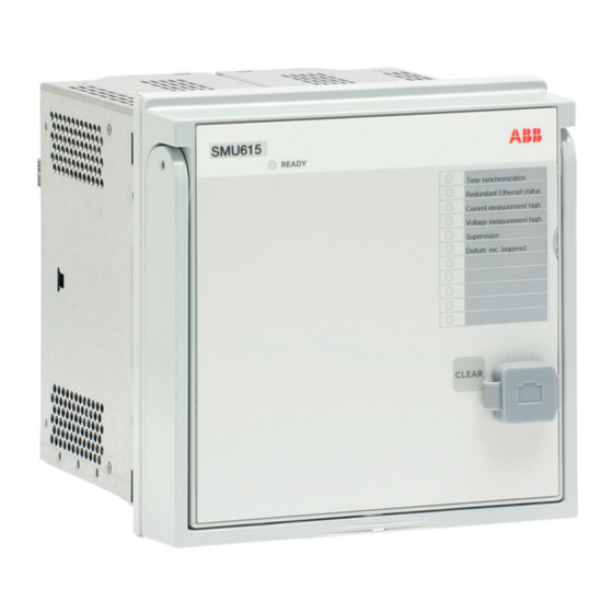
Page 24: Leds
Section 2 1MRS758407 B SMU615 overview GUID-45DD21AE-B64A-4508-B6DF-FC264C2171DB V2 EN Figure 2: Example of the LHMI 2.2.1 LEDs The LHMI includes a dedicated Ready LED indicator and 11 matrix programmable LEDs on front of the LHMI. The LEDs can be configured with PCM600 and the operation mode can be selected via WHMI or PCM600. -
Page 25: Web Hmi
Section 2 1MRS758407 B SMU615 overview GUID-9101BAA6-AA5B-4747-A817-0FE8C8831B9F V2 EN Figure 3: LHMI command push button and RJ-45 communication port Web HMI The WHMI allows secure access to the merging unit via a Web browser. When the Secure Communication parameter in the merging unit is activated, the Web server is forced to take a secured (HTTPS) connection to WHMI using TLS encryption. -
Page 26: Authorization
Section 2 1MRS758407 B SMU615 overview GUID-27E59B74-A1B0-48F3-BE04-6ED4B17550A2 V1 EN Figure 4: Example view of the WHMI The WHMI can be accessed locally and remotely. • Locally by connecting the laptop to the merging unit via the front communication port. • Remotely over LAN/WAN. -
Page 27: Audit Trail
Section 2 1MRS758407 B SMU615 overview Table 2: Predefined user categories Username User rights VIEWER Read only access OPERATOR • Clearing indications ENGINEER • Changing settings • Clearing event list • Clearing disturbance records • Changing system settings such as IP address, serial baud rate or disturbance recorder settings •... - Page 28 Section 2 1MRS758407 B SMU615 overview Table 3: Audit trail events Audit trail event Description Configuration change Configuration files changed Firmware change Firmware changed Firmware change fail Firmware change failed Attached to retrofit test case Unit has been attached to retrofit case Removed from retrofit test case Removed from retrofit test case Control remote...
-
Page 29: Communication
Section 2 1MRS758407 B SMU615 overview Audit trail event Authority logging level Firmware change fail ● ● ● Attached to retrofit test case ● ● ● Removed from retrofit test case ● ● ● Control remote ● ● Test on ●... -
Page 30: Ethernet Redundancy
Section 2 1MRS758407 B SMU615 overview 2.5.1 Ethernet redundancy IEC 61850 specifies a network redundancy scheme that improves the system availability for substation communication. It is based on two complementary protocols defined in the IEC 62439-3:2012 standard: parallel redundancy protocol PRP-1 and high-availability seamless redundancy HSR protocol. - Page 31 Section 2 1MRS758407 B SMU615 overview COM600 SCADA Ethernet switch Ethernet switch IEC 61850 PRP GUID-334D26B1-C3BD-47B6-BD9D-2301190A5E9D V3 EN Figure 5: PRP solution In case a laptop or a PC workstation is connected as a non-PRP node to one of the PRP networks, LAN A or LAN B, it is recommended to use a redundancy box device or an Ethernet switch with similar functionality between the PRP network and SAN to remove additional PRP information from the Ethernet frames.
-
Page 32: Process Bus
Section 2 1MRS758407 B SMU615 overview GUID-207430A7-3AEC-42B2-BC4D-3083B3225990 V3 EN Figure 6: HSR solution 2.5.2 Process bus Process bus IEC 61850-9-2 defines the transmission of Sampled Measured Values within the substation automation system. International Users Group created a guideline IEC 61850-9-2 LE that defines an application profile of IEC 61850-9-2 to facilitate implementation and enable interoperability. - Page 33 Section 2 1MRS758407 B SMU615 overview Protection and Substation Control Relay Merging Unit Current Sensors GUID-9215CB30-01E3-4D90-B9BA-473FE657DE4F V2 EN Figure 7: SMU615 sending current measurements as sampled measured values to a protection relay SMU615 Technical Manual...
- Page 34 Section 2 1MRS758407 B SMU615 overview Protection and Substation Control Relay Merging Unit Voltage Sensor Current Sensors GUID-1504F322-B34D-409E-A7A9-512FB235921A V2 EN Figure 8: SMU615 sending voltage measurements as sampled measured values to protection relays SMU615 Technical Manual...
- Page 35 Section 2 1MRS758407 B SMU615 overview Smart Substation Control and Protection Substation Merging Unit with Binary I/0 SMV and GOOSE Current Sensors GUID-D8A746E4-6E21-4A4F-A963-7D66FE6A7255 V1 EN Figure 9: Smart substation control and protection SSC600 with SMU615 The merging unit supports IEC 61850 process bus with sampled values of analog currents and voltages.
-
Page 36: Secure Communication
Section 2 1MRS758407 B SMU615 overview Primary Secondary IEEE 1588 v2 IEEE 1588 v2 master clock master clock (optional) Managed HSR Managed HSR Ethernet Ethernet switch switch IEC 61850 Backup 1588 master clock GUID-7C56BC1F-F1B2-4E74-AB8E-05001A88D53D V6 EN Figure 10: Example network topology with process bus, redundancy and IEEE 1588 v2 time synchronization The process bus is available for all merging units. -
Page 37: Section 3 Basic Functions
Section 3 1MRS758407 B Basic functions Section 3 Basic functions General parameters Table 5: Analog input settings, phase currents Parameter Values (Range) Unit Step Default Description Primary current 1.0...6000.0 100.0 Rated primary current Secondary current 2=1A 2=1A Rated secondary current 3=5A Amplitude Corr A 0.9000...1.1000... - Page 38 Section 3 1MRS758407 B Basic functions Parameter Values (Range) Unit Step Default Description Amplitude Corr C 0.9000...1.1000 0.0001 1.0000 Phase C Voltage phasor magnitude correction of an external voltage transformer Division ratio 1000...20000 10000 Voltage sensor division ratio Voltage input type 1=Voltage trafo 1=Voltage trafo Type of the voltage input...
- Page 39 Section 3 1MRS758407 B Basic functions Adjust the binary input threshold voltage correctly. The threshold voltage should be comparable to the nominal value instead of the default minimum value. The factory default is 16 V to ensure the binary inputs’ operation regardless of the auxiliary voltage used (24, 48, 60, 110, 125, 220 or 250 V DC).
- Page 40 Section 3 1MRS758407 B Basic functions Table 14: Ethernet rear port settings Parameter Values (Range) Unit Step Default Description IP address 192.168.2.10 IP address for rear port(s) Subnet mask 255.255.255.0 Subnet mask for rear port(s) Default gateway 192.168.2.1 Default gateway for rear port(s) Mac address XX-XX-XX-XX- Mac address for rear port(s)
-
Page 41: Self-Supervision
Section 3 1MRS758407 B Basic functions Self-supervision The merging unit's extensive self-supervision system continuously supervises the software and the electronics. It handles run-time fault situation and informs the user about a fault through the communication channels. There are two types of fault indications. •... - Page 42 1MRS758407 B Basic functions The internal fault code indicates the type of internal fault. When a fault appears, the code must be recorded so that it can be reported to ABB customer service. Table 18: Internal fault indications and codes...
-
Page 43: Warnings
WHMI. If a warning appears, record the name and code so that it can be provided to ABB customer service. Table 19: Warning indications and codes... -
Page 44: Programmable Leds
Section 3 1MRS758407 B Basic functions Warning indication Warning code Additional information Warning Error in the GOOSE connections. GOOSE input error ACT error Error in the ACT connections. Warning Error in the GOOSE message receiving. GOOSE Rx. error Warning Analog channel configuration error. AFL error Warning Error in the SMV configuration. - Page 45 Section 3 1MRS758407 B Basic functions GUID-45DD21AE-B64A-4508-B6DF-FC264C2171DB V2 EN Figure 13: Programmable LEDs on the right side of the LHMI All the programmable LEDs in the HMI of the merging unit have two colors, green and red. For each LED, the different colors are individually controllable. Each LED has two control inputs, ALARM and OK.
- Page 46 Section 3 1MRS758407 B Basic functions The LED status also provides a means for resetting the individual LED via communication. The LED can also be reset from configuration with the RESET input. The resetting and clearing function for all LEDs is under the Clear menu. The menu structure for the programmable LEDs is presented in Figure 14.
-
Page 47: Signals
Section 3 1MRS758407 B Basic functions "Follow-F": Follow Signal, Flashing Similar to "Follow-S", but instead the LED is flashing when the input is active, Non- latched. "Latched-S": Latched, ON This mode is a latched function. At the activation of the input signal, the alarm shows a steady light. - Page 48 Section 3 1MRS758407 B Basic functions Name Type Default Description BOOLEAN 0=False Ok input for LED 2 ALARM BOOLEAN 0=False Alarm input for LED 2 RESET BOOLEAN 0=False Reset input for LED 2 BOOLEAN 0=False Ok input for LED 3 ALARM BOOLEAN 0=False...
-
Page 49: Settings
Section 3 1MRS758407 B Basic functions 3.3.4 Settings Table 21: Non group settings Parameter Values (Range) Unit Step Default Description Alarm colour 1=Green 2=Red Colour for the alarm state of the LED 2=Red Alarm mode 0=Follow-S 0=Follow-S Alarm mode for programmable LED 1 1=Follow-F 2=Latched-S 3=LatchedAck-F-S... -
Page 50: Monitored Data
Section 3 1MRS758407 B Basic functions Parameter Values (Range) Unit Step Default Description Description Programmable Programmable LED description LEDs LED 8 Alarm mode 0=Follow-S 0=Follow-S Alarm mode for programmable LED 9 1=Follow-F 2=Latched-S 3=LatchedAck-F-S Description Programmable Programmable LED description LEDs LED 9 Alarm mode 0=Follow-S 0=Follow-S... -
Page 51: Time Synchronization
Section 3 1MRS758407 B Basic functions Name Type Values (Range) Unit Description Programmable LED Enum 0=None Status of programmable 1=Ok LED 9 3=Alarm Programmable LED Enum 0=None Status of programmable 1=Ok LED 10 3=Alarm Programmable LED Enum 0=None Status of programmable 1=Ok LED 11 3=Alarm... -
Page 52: Signals
Section 3 1MRS758407 B Basic functions as 1588 master, with options “Basic IEEE1588” and “Power Profile”. In the “Power Profile” mode, the TLVs required by the IEEE C37.238-2011 Power Profile are included in announce frames. Time master supervision functionality is provided when the merging unit itself is synchronized from an external source (master). - Page 53 Section 3 1MRS758407 B Basic functions Table 25: Time settings Parameter Values (Range) Unit Step Default Description Synch source 0=None 3=IEEE 1588 Time synchronization source 3=IEEE 1588 PTP domain ID 0...255 The domain is identified by an integer, the domainNumber, in the range of 0 to 255. 0...255 PTP priority 1, in the range of 0 to 255.
-
Page 54: Test Mode
Section 3 1MRS758407 B Basic functions Parameter Values (Range) Unit Step Default Description DST off date (month) 1=January 9=September Daylight saving time off, date (dd:mm) 2=February 3=March 4=April 5=May 6=June 7=July 8=August 9=September 10=October 11=November 12=December DST off day (weekday) 0=reserved 0=reserved Daylight saving time off, day of week... -
Page 55: Application Configuration And Test Mode
Section 3 1MRS758407 B Basic functions Table 28: Test mode Test mode Description TEST_MODE BEH_BLK Normal mode Normal operation FALSE IED blocked Function working as in “Normal mode” but ACT TRUE configuration can be used to block physical outputs to process. Control function commands blocked. -
Page 56: Application Configuration And Control Mode
Section 3 1MRS758407 B Basic functions Behavior data objects under CTRL logical device follow CTRL.LLN0.Mod value. If "On" is selected, behavior data objects follow the mode of the corresponding logical device. 3.5.5 Application configuration and Control mode The physical outputs from commands to process are blocked with “Blocked“ mode. If physical outputs need to be blocked totally, meaning also commands from the binary inputs, the application configuration must be used to block these signals. -
Page 57: Signals
Section 3 1MRS758407 B Basic functions 3.5.8 Signals Table 31: CONTROL input signals Name Type Default Description CTRL_OFF BOOLEAN Control OFF CTRL_LOC BOOLEAN Control local CTRL_STA BOOLEAN Control station CTRL_REM BOOLEAN Control remote CTRL_ALL BOOLEAN Control all Table 32: TEST_MODE output signals Name Type Description... -
Page 58: Sensor Inputs For Currents And Voltages
Section 3 1MRS758407 B Basic functions Sensor inputs for currents and voltages This chapter gives short examples on how to define the correct parameters for sensors. Sensors have corrections factors, measured and verified by the sensor manufacturer, to increase the measurement accuracy of primary values. - Page 59 VT connection parameter which is always set to “WYE” type. The division ratio for ABB voltage sensors is most often 10000:1. Thus, the Division ratio parameter is usually set to “10000”. The primary voltage is proportionally divided by this division ratio.
-
Page 60: Binary Input
Section 3 1MRS758407 B Basic functions Binary input 3.8.1 Binary input filter time The filter time eliminates debounces and short disturbances on a binary input. The filter time is set for each binary input of the merging unit. GUID-13DA5833-D263-4E23-B666-CF38B1011A4B V1 EN Figure 21: Binary input filtering 3 Input signal... -
Page 61: Binary Input Inversion
Section 3 1MRS758407 B Basic functions 3.8.2 Binary input inversion The parameter Input # invert is used to invert a binary input. Table 38: Binary input states Control voltage Input # invert State of binary input FALSE (0) TRUE (1) TRUE (1) FALSE (0) When a binary input is inverted, the state of the input is TRUE (1) when no control... -
Page 62: Power Output Contacts
Section 3 1MRS758407 B Basic functions Power output contacts are used when the current rating requirements of the contacts are high, for example, for controlling a breaker, such as energizing the breaker trip and closing coils. The contacts used for external signalling, recording and indicating, the signal outputs, need to adjust to smaller currents, but they can require a minimum current (burden) to ensure a guaranteed operation. -
Page 63: Double-Pole Power Outputs Po3 And Po4 With Trip Circuit Supervision
Section 3 1MRS758407 B Basic functions X100 GUID-4E1E21B1-BEEC-4351-A7BE-9D2DBA451985 V1 EN Figure 22: Dual single-pole power output contacts PO1 and PO2 3.9.1.2 Double-pole power outputs PO3 and PO4 with trip circuit supervision The power outputs PO3 and PO4 are double-pole normally open/form A power outputs with trip circuit supervision. -
Page 64: Dual Single-Pole High-Speed Power Outputs Hso1, Hso2 And Hso3
Section 3 1MRS758407 B Basic functions X100 TCS1 TCS2 GUID-5A0502F7-BDC4-424A-BF19-898025FCCBD7 V1 EN Figure 23: Double-pole power outputs PO3 and PO4 with trip circuit supervision Power outputs PO3 and PO4 are included in the power supply module located in slot X100 of the merging unit. 3.9.1.3 Dual single-pole high-speed power outputs HSO1, HSO2 and HSO3 HSO1, HSO2 and HSO3 are dual parallel connected, single-pole, normally open/form... -
Page 65: Signal Output Contacts
Section 3 1MRS758407 B Basic functions X110 HSO1 HSO2 HSO3 GUID-38EDD366-7456-4933-B49E-0F43FE1D6C39 V1 EN Figure 24: High-speed power outputs HSO1, HSO2 and HSO3 The reset time of the high-speed output contacts is longer than that of the conventional output contacts. High-speed power contacts are part of the card BIO0007 with eight binary inputs and three HSOs. -
Page 66: Signal Outputs So1 And So2 In Power Supply Module
Section 3 1MRS758407 B Basic functions X100 GUID-C09595E9-3C42-437A-BDB2-B20C35FA0BD2 V1 EN Figure 25: Internal fault signal output IRF 3.9.2.2 Signal outputs SO1 and SO2 in power supply module Signal outputs (normally open/form A or change-over/form C) SO1 (dual parallel form C) and SO2 (single contact/form A) are part of the power supply module of the merging unit. -
Page 67: Iec 61850-9-2 Le Sampled Values Sending Smvsender
Section 3 1MRS758407 B Basic functions 3.10.1 IEC 61850-9-2 LE sampled values sending SMVSENDER 3.10.1.1 Functionality The SMVSENDER function block is used for activating the SMV sending functionality. It adds/removes the sampled value control block and the related data set into/from the sending device's configuration. -
Page 68: Settings
Section 3 1MRS758407 B Basic functions 3.10.2.4 Settings Table 42: ILTCTR1 Non group settings (Basic) Parameter Values (Range) Unit Step Default Description Primary current 1.0...6000.0 100.0 Rated primary current Secondary current 2=1A 2=1A Rated secondary current 3=5A Amplitude Corr A 0.9000...1.1000 0.0001 1.0000... -
Page 69: Restctr Function Block
Section 3 1MRS758407 B Basic functions 3.10.3 RESTCTR function block 3.10.3.1 Function block RESTCTR GUID-878204B1-5920-4A4F-A73B-3779C062B2B1 V1 EN Figure 28: Function block 3.10.3.2 Settings Table 45: RESTCTR1_ct Non group settings (Basic) Parameter Values (Range) Unit Step Default Description Primary current 1.0...6000.0 100.0 Primary current Secondary current... -
Page 70: Goosercv_Bin Function Block
Section 3 1MRS758407 B Basic functions Settings The GOOSE function blocks do not have any parameters available in PCM600. 3.11.1 GOOSERCV_BIN function block 3.11.1.1 Function block GUID-44EF4D6E-7389-455C-BDE5-B127678E2CBC V1 EN Figure 29: Function block 3.11.1.2 Functionality The GOOSERCV_BIN function is used to connect the GOOSE binary inputs to the application. -
Page 71: Signals
Section 3 1MRS758407 B Basic functions 3.11.2.3 Signals Table 48: GOOSERCV_DP Output signals Name Type Description Dbpos Output signal VALID BOOLEAN Output signal 3.11.3 GOOSERCV_INT8 function block 3.11.3.1 Function block GUID-B4E1495B-F797-4CFF-BD19-AF023EA2D3D9 V1 EN Figure 31: Function block 3.11.3.2 Functionality The GOOSERCV_INT8 function is used to connect the GOOSE 8 bit integer inputs to the application. -
Page 72: Functionality
Section 3 1MRS758407 B Basic functions 3.11.4.2 Functionality The GOOSERCV_INTL function is used to connect the GOOSE double binary input to the application and extracting single binary position signals from the double binary position signal. The OP output signal indicates that the position is open. Default value (0) is used if VALID output indicates invalid status. -
Page 73: Goosercv_Int32 Function Block
Section 3 1MRS758407 B Basic functions 3.11.6 GOOSERCV_INT32 function block 3.11.6.1 Function block GUID-61FF1ECC-507D-4B6D-8CA5-713A59F58D5C V1 EN Figure 34: Function block 3.11.6.2 Functionality The GOOSERCV_INT32 function block is used to connect GOOSE 32 bit integer inputs to the application. 3.11.6.3 Signals Table 52: GOOSERCV_INT32 Output signals Name... -
Page 74: Signals
Section 3 1MRS758407 B Basic functions application logic quality bit propagation, each (simple and even combined) signal has quality which can be evaluated. The OUT output indicates quality good of the input signal. Input signals that have no quality bits set or only test bit is set, will indicate quality good status. 3.12.1.3 Signals Table 53:... -
Page 75: Qty_Goose_Comm Function Block
Section 3 1MRS758407 B Basic functions Table 56: QTY_BAD Output signals Name Type Description BOOLEAN Output signal 3.12.3 QTY_GOOSE_COMM function block 3.12.3.1 Function block GUID-0FDC082E-C9A8-4B02-9878-6C49E44B7C0E V1 EN Figure 37: Function block 3.12.3.2 Functionality The QTY_GOOSE_COMM function block evaluates the peer device communication status from the quality bits of the input signal and passes it as a Boolean signal to the application. -
Page 76: T_Health Function Block
Section 3 1MRS758407 B Basic functions 3.12.4 T_HEALTH function block 3.12.4.1 Function block GUID-B5FCAE66-8026-4D5F-AC38-028E5A8171BB V1 EN Figure 38: Function block 3.12.4.2 Functionality The T_HEALTH function evaluates enumerated data of “Health” data attribute. This function block can only be used with GOOSE. The IN input can be connected to GOOSERCV_ENUM function block, which is receiving the LD0.LLN0.Health.stVal data attribute sent by another device. -
Page 77: T_F32_Int8 Function Block
Section 3 1MRS758407 B Basic functions 3.12.5 T_F32_INT8 function block 3.12.5.1 Function block GUID-F0F44FBF-FB56-4BC2-B421-F1A7924E6B8C V1 EN Figure 39: Function block 3.12.5.2 Functionality The T_F32_INT8 function is used to convert 32-bit floating type values to 8-bit integer type. The rounding operation is included. Output value saturates if the input value is below the minimum or above the maximum value. -
Page 78: Signals
Section 3 1MRS758407 B Basic functions LD0.<function>.Str.dirGeneral or LD0.<function>.Dir.dirGeneral data attribute sent by another device. In case the GOOSERCV_ENUM function block does not receive the value from the sending device or it is invalid, the default value (0) is used in function outputs. The outputs FWD and REV are extracted from the enumerated input value. -
Page 79: Signals
Section 3 1MRS758407 B Basic functions 3.12.7.3 Signals Table 66: T_TCMD input signals Name Type Default Description Enum Input signal Table 67: T_TCMD output signals Name Type Description RAISE BOOLEAN Raise command LOWER BOOLEAN Lower command 3.12.8 T_TCMD_BIN function block 3.12.8.1 Function block GUID-A5C813D8-399A-4FBC-B1A0-E62E5C423EA5 V1 EN... -
Page 80: T_Bin_Tcmd Function Block
Section 3 1MRS758407 B Basic functions Table 70: T_TCMD_BIN output signals Name Type Description RAISE BOOLEAN Raise command LOWER BOOLEAN Lower command 3.12.9 T_BIN_TCMD function block 3.12.9.1 Function block GUID-54A013A3-E253-4A06-B033-01C7E11EC997 V1 EN Figure 43: Function block 3.12.9.2 Functionality The T_BIN_TCMD function is used to convert Boolean input signals to 32 bit integer output signals. -
Page 81: Configurable Logic Blocks
Section 3 1MRS758407 B Basic functions 3.13 Configurable logic blocks 3.13.1 Standard configurable logic blocks 3.13.1.1 OR function block Function block GUID-A845F2F1-DCC2-40C9-8A77-893EF5694436 V1 EN Figure 44: Function blocks Functionality OR, OR6 and OR20 are used to form general combinatory expressions with Boolean variables. - Page 82 Section 3 1MRS758407 B Basic functions Table 75: OR6 Input signals Name Type Default Description BOOLEAN Input signal 1 BOOLEAN Input signal 2 BOOLEAN Input signal 3 BOOLEAN Input signal 4 BOOLEAN Input signal 5 BOOLEAN Input signal 6 Table 76: OR20 Input signals Name Type...
-
Page 83: And Function Block
Section 3 1MRS758407 B Basic functions Table 79: OR20 Output signal Name Type Description BOOLEAN Output signal Settings The function does not have any parameters available in PCM600. 3.13.1.2 AND function block Function block GUID-F560A373-4DB9-42E9-B687-DF4A3E45359C V1 EN Figure 45: Function blocks Functionality AND, AND6 and AND20 are used to form general combinatory expressions with Boolean variables. - Page 84 Section 3 1MRS758407 B Basic functions Table 81: AND6 Input signals Name Type Default Description BOOLEAN Input signal 1 BOOLEAN Input signal 2 BOOLEAN Input signal 3 BOOLEAN Input signal 4 BOOLEAN Input signal 5 BOOLEAN Input signal 6 Table 82: AND20 Input signals Name Type...
-
Page 85: Xor Function Block
Section 3 1MRS758407 B Basic functions Table 85: AND20 Output signal Name Type Description BOOLEAN Output signal Settings The function does not have any parameters available in PCM600. 3.13.1.3 XOR function block Function block GUID-9C247C8A-03A5-4F08-8329-F08BE7125B9A V1 EN Figure 46: Function block Functionality The exclusive OR function XOR is used to generate combinatory expressions with Boolean variables. -
Page 86: Not Function Block
Section 3 1MRS758407 B Basic functions 3.13.1.4 NOT function block Function block GUID-0D0FC187-4224-433C-9664-908168EE3626 V1 EN Figure 47: Function block Functionality NOT is used to generate combinatory expressions with Boolean variables. NOT inverts the input signal. Signals Table 88: NOT Input signal Name Type Default... -
Page 87: Min3 Function Block
Section 3 1MRS758407 B Basic functions Signals Table 90: MAX3 Input signals Name Type Default Description FLOAT32 Input signal 1 FLOAT32 Input signal 2 FLOAT32 Input signal 3 Table 91: MAX3 Output signal Name Type Description FLOAT32 Output signal Settings The function does not have any parameters available in PCM600. -
Page 88: R_Trig Function Block
Section 3 1MRS758407 B Basic functions Settings The function does not have any parameters available in PCM600. 3.13.1.7 R_TRIG function block Function block GUID-3D0BBDC3-4091-4D8B-A35C-95F6289E6FD8 V1 EN Figure 50: Function block Functionality R_TRIG is used as a rising edge detector. R_TRIG detects the transition from FALSE to TRUE at the CLK input. When the rising edge is detected, the element assigns the output to TRUE. -
Page 89: T_Pos_Xx Function Blocks
Section 3 1MRS758407 B Basic functions The function detects the transition from TRUE to FALSE at the CLK input. When the falling edge is detected, the element assigns the Q output to TRUE. At the next execution round, the output is returned to FALSE despite the state of the input. Signals Table 96: F_TRIG Input signals... -
Page 90: Switchr Function Block
Section 3 1MRS758407 B Basic functions Signals Table 99: T_POS_CL Input signals Name Type Default Description Double binary Input signal Table 100: T_POS_OP Input signals Name Type Default Description Double binary Input signal Table 101: T_POS_OK Input signals Name Type Default Description Double binary... -
Page 91: Switchi32 Function Block
Section 3 1MRS758407 B Basic functions Functionality SWITCHR switching block for REAL data type is operated by the CTL_SW input, selects the output value OUT between the IN1 and IN2 inputs. CTL_SW FALSE TRUE Signals Table 105: SWITCHR Input signals Name Type Default... -
Page 92: Sr Function Block
Section 3 1MRS758407 B Basic functions Signals Table 108: SWITCHI32 input signals Name Type Default Description CTL_SW BOOLEAN Control Switch INT32 Input signal 1 INT32 Input signal 2 Table 109: SWITCHI32 output signals Name Type Description INT32 Output signal 3.13.1.12 SR function block Function block GUID-0B62CAED-F8A4-4738-B546-677DA362FE24 V2 EN... -
Page 93: Rs Function Block
Section 3 1MRS758407 B Basic functions Signals Table 111: SR Input signals Name Type Default Description BOOLEAN 0=False Set Q output when set BOOLEAN 0=False Resets Q output when Table 112: SR Output signals Name Type Description BOOLEAN Q status NOTQ BOOLEAN NOTQ status... -
Page 94: Minimum Pulse Timer
Section 3 1MRS758407 B Basic functions Signals Table 114: RS Input signals Name Type Default Description BOOLEAN 0=False Set Q output when set BOOLEAN 0=False Resets Q output when Table 115: RS Output signals Name Type Description BOOLEAN Q status NOTQ BOOLEAN NOTQ status... -
Page 95: Minimum Pulse Timer Tpsgapc
Section 3 1MRS758407 B Basic functions GUID-8196EE39-3529-46DC-A161-B1C40224559F V1 EN Figure 58: A = Trip pulse is shorter than Pulse time setting, B = Trip pulse is longer than Pulse time setting Signals Table 117: TPGAPC Output signals Name Type Description OUT1 BOOLEAN Output 1 status... - Page 96 Section 3 1MRS758407 B Basic functions Functionality The Minimum second pulse timer function TPSGAPC contains two independent timers. The function has a settable pulse length (in seconds). The timers are used for setting the minimum pulse length for example, the signal outputs. Once the input is activated, the output is set for a specific duration using the Pulse time setting.
-
Page 97: Minimum Pulse Timer Tpmgapc
Section 3 1MRS758407 B Basic functions 3.13.2.3 Minimum pulse timer TPMGAPC Function block GUID-AB26B298-F7FA-428F-B498-6605DB5B0661 V1 EN Figure 61: Function block Functionality The Minimum minute pulse timer function TPMGAPC contains two independent timers. The function has a settable pulse length (in minutes). The timers are used for setting the minimum pulse length for example, the signal outputs. -
Page 98: Pulse Timer Ptgapc
Section 3 1MRS758407 B Basic functions 3.13.3 Pulse timer PTGAPC 3.13.3.1 Function block GUID-2AA275E8-31D4-4CFE-8BDA-A377213BBA89 V1 EN Figure 63: Function block 3.13.3.2 Functionality The pulse timer function PTGAPC contains eight independent timers. The function has a settable pulse length. Once the input is activated, the output is set for a specific duration using the Pulse delay time setting. -
Page 99: Settings
Section 3 1MRS758407 B Basic functions Table 128: PTGAPC Output signals Name Type Description BOOLEAN Output 1 status BOOLEAN Output 2 status BOOLEAN Output 3 status BOOLEAN Output 4 status BOOLEAN Output 5 status BOOLEAN Output 6 status BOOLEAN Output 7 status BOOLEAN Output 8 status 3.13.3.4... -
Page 100: Time Delay Off (8 Pcs) Tofgapc
Section 3 1MRS758407 B Basic functions 3.13.4 Time delay off (8 pcs) TOFGAPC 3.13.4.1 Function block GUID-6BFF6180-042F-4526-BB80-D53B2458F376 V1 EN Figure 65: Function block 3.13.4.2 Functionality The time delay off (8 pcs) function TOFGAPC can be used, for example, for a drop- off-delayed output related to the input signal. -
Page 101: Settings
Section 3 1MRS758407 B Basic functions Name Type Default Description BOOLEAN 0=False Input 6 status BOOLEAN 0=False Input 7 status BOOLEAN 0=False Input 8 status Table 132: TOFGAPC Output signals Name Type Description BOOLEAN Output 1 status BOOLEAN Output 2 status BOOLEAN Output 3 status BOOLEAN... -
Page 102: Time Delay On (8 Pcs) Tongapc
Section 3 1MRS758407 B Basic functions 3.13.5 Time delay on (8 pcs) TONGAPC 3.13.5.1 Function block GUID-B694FC27-E6AB-40FF-B1C7-A7EB608D6866 V1 EN Figure 67: Function block 3.13.5.2 Functionality The time delay on (8 pcs) function TONGAPC can be used, for example, for time- delaying the output related to the input signal. -
Page 103: Settings
Section 3 1MRS758407 B Basic functions Name Type Default Description BOOLEAN 0=False Input 6 BOOLEAN 0=False Input 7 BOOLEAN 0=False Input 8 Table 136: TONGAPC Output signals Name Type Description BOOLEAN Output 1 BOOLEAN Output 2 BOOLEAN Output 3 BOOLEAN Output 4 BOOLEAN Output 5... -
Page 104: Set Reset (8 Pcs) Srgapc
Section 3 1MRS758407 B Basic functions 3.13.6 Set reset (8 pcs) SRGAPC 3.13.6.1 Function block GUID-93136D07-FDC4-4356-95B5-54D3B2FC9B1C V1 EN Figure 69: Function block 3.13.6.2 Functionality The set-reset (8 pcs) function SRGAPC is a simple SR flip-flop with a memory that can be set or that can reset an output from the S# or R# inputs, respectively. The function contains eight independent set-reset flip-flop latches where the SET input has the higher priority over the RESET input. -
Page 105: Signals
Section 3 1MRS758407 B Basic functions 3.13.6.3 Signals Table 140: SRGAPC Input signals Name Type Default Description BOOLEAN 0=False Set Q1 output when set BOOLEAN 0=False Resets Q1 output when set BOOLEAN 0=False Set Q2 output when set BOOLEAN 0=False Resets Q2 output when set BOOLEAN 0=False... -
Page 106: Settings
Section 3 1MRS758407 B Basic functions 3.13.6.4 Settings Table 142: SRGAPC Non group settings (Basic) Parameter Values (Range) Unit Step Default Description Reset Q1 0=Cancel 0=Cancel Resets Q1 output when set 1=Reset Reset Q2 0=Cancel 0=Cancel Resets Q2 output when set 1=Reset Reset Q3 0=Cancel... -
Page 107: Signals
Section 3 1MRS758407 B Basic functions 3.13.7.3 Signals Table 143: MVGAPC Output signals Name Type Description BOOLEAN Q1 status BOOLEAN Q2 status BOOLEAN Q3 status BOOLEAN Q4 status BOOLEAN Q5 status BOOLEAN Q6 status BOOLEAN Q7 status BOOLEAN Q8 status 3.13.7.4 Settings Table 144:... -
Page 108: Functionality
Section 3 1MRS758407 B Basic functions 3.13.8.2 Functionality Local/Remote control supports multilevel access for control operations in substations according to the IEC 61850 standard. Multilevel control access with separate station control access level is not supported by other protocols than IEC 61850. The actual Local/Remote control state is evaluated by the priority scheme on the function block inputs. -
Page 109: Station Authority Level "L,R
Section 3 1MRS758407 B Basic functions 3.13.8.4 Station authority level “L,R” In this scenario only local or remote control access is allowed. Control access with IEC 61850 command originator category station is interpreted as remote access. There is no multilevel access. REMOTE LOCAL IEC 61850... -
Page 110: Station Authority Level "L,S,R
Section 3 1MRS758407 B Basic functions REMOTE LOCAL IEC 61850 IEC 61850 IEC 61850 IEC 61850 IEC 61850 IEC 61850 IEC 61850 IEC 61850 remote remote remote remote remote remote remote remote GUID-10D77281-14C3-4066-B641-98A6F8904E39 V1 EN Figure 73: Station authority is “L,R,L+R” When station authority level “L,R, L+R”... -
Page 111: Station Authority Level "L,S,S+R,L+S,L+S+R
Section 3 1MRS758407 B Basic functions LOCAL REMOTE STATION IEC 61850 IEC 61850 IEC 61850 IEC 61850 remote remote remote remote IEC 61850 IEC 61850 IEC 61850 IEC 61850 station station station station GUID-7BC51FAF-B097-4CD9-AFF4-6D1F3D548C7F V1 EN Figure 74: Station authority is “L,S,R” When the station authority level “L,S,R”... - Page 112 Section 3 1MRS758407 B Basic functions access controllable objects and they remain reserved until the previously started control operation is first completed by the client. LOCAL STATION L+S+R IEC 61850 IEC 61850 IEC 61850 IEC 61850 IEC 61850 IEC 61850 remote remote remote...
-
Page 113: Signals
Section 3 1MRS758407 B Basic functions 3.13.8.8 Signals Table 150: CONTROL input signals Name Type Default Description CTRL_OFF BOOLEAN Control input OFF CTRL_LOC BOOLEAN Control input Local CTRL_STA BOOLEAN Control input Station CTRL_REM BOOLEAN Control input Remote CTRL_ALL BOOLEAN Control input All Table 151: CONTROL output signals Name... -
Page 114: Monitored Data
Section 3 1MRS758407 B Basic functions 3.13.8.10 Monitored data Table 153: Monitored data Name Type Values (Range) Unit Description Command response Enum 0=No commands Latest command 1=Select open response 2=Select close 3=Operate open 4=Operate close 5=Direct open 6=Direct close 7=Cancel 8=Position reached 9=Position... -
Page 115: Generic Control Point (16 Pcs) Spcgapc
Section 3 1MRS758407 B Basic functions 3.13.9 Generic control point (16 pcs) SPCGAPC 3.13.9.1 Function block GUID-3A7D9472-39BF-4522-83CA-89BFBA1800E6 V1 EN Figure 76: Function block 3.13.9.2 Functionality The generic control points function SPCGAPC contains 16 independent control points. SPCGAPC offers the capability to activate its outputs through a local or remote control. -
Page 116: Signals
Section 3 1MRS758407 B Basic functions GUID-F0078144-A40B-4A72-915A-0E6665F8DEB1 V1 EN Figure 77: Operation in "Toggle" mode The BLOCK input can be used for blocking the functionality of the outputs. The operation of the BLOCK input depends on the Operation mode setting. If Operation mode is "Toggle", the output state freezes and cannot be changed while the BLOCK input is active. -
Page 117: Settings
Section 3 1MRS758407 B Basic functions Table 155: SPCGAPC Output signals Name Type Description BOOLEAN Output 1 status BOOLEAN Output 2 status BOOLEAN Output 3 status BOOLEAN Output 4 status BOOLEAN Output 5 status BOOLEAN Output 6 status BOOLEAN Output 7 status BOOLEAN Output 8 status BOOLEAN... - Page 118 Section 3 1MRS758407 B Basic functions Parameter Values (Range) Unit Step Default Description Description SPCGAPC1 Generic control point description Output 3 Operation mode 0=Pulsed -1=Off Operation mode for generic control point 1=Toggle/ Persistent -1=Off Pulse length 10...3600000 1000 Pulse length for pulsed operation mode Description SPCGAPC1 Generic control point description...
-
Page 119: Factory Settings Restoration
Section 3 1MRS758407 B Basic functions Parameter Values (Range) Unit Step Default Description Operation mode 0=Pulsed -1=Off Operation mode for generic control point 1=Toggle/ Persistent -1=Off Pulse length 10...3600000 1000 Pulse length for pulsed operation mode Description SPCGAPC1 Generic control point description Output 11 Operation mode 0=Pulsed... -
Page 120: Ethernet Channel Supervision Function Blocks
Section 3 1MRS758407 B Basic functions are restored. For further information on restoring factory settings, see the operation manual. 3.15 ETHERNET channel supervision function blocks 3.15.1 Redundant Ethernet channel supervision RCHLCCH 3.15.1.1 Function block GUID-CD9E923F-7B50-45C0-AE3E-39F576E01906 V1 EN Figure 78: Function block 3.15.1.2 Functionality Redundant Ethernet channel supervision RCHLCCH represents LAN A and LAN B... -
Page 121: Settings
Section 3 1MRS758407 B Basic functions 3.15.1.4 Settings Table 158: Redundancy settings Parameter Values (Range) Unit Step Default Description Redundant None None Mode selection for Ethernet switch on mode redundant communication modules. The "None" mode is used with normal and Self-healing Ethernet topologies. 3.15.1.5 Monitored data Monitored data is available in four locations. -
Page 122: Signals
Section 3 1MRS758407 B Basic functions 3.15.2.3 Signals Table 159: SCHLCCH1 output signals Parameter Values (Range) Unit Step Default Description CH1LIV True Status of Ethernet channel X1/LAN. False Value is "True" if the port is receiving Ethernet frames. Valid only when Redundant mode is set to "None"... -
Page 123: Settings
Section 3 1MRS758407 B Basic functions 3.15.2.4 Settings Table 162: Port mode settings Parameter Values (Range) Unit Step Default Description Port 1 Mode Mode selection for rear port(s). If port is not used, it can be set to “Off”. Port cannot be set to “Off”... -
Page 125: Section 4 Protection Related Functions
Section 4 1MRS758407 B Protection related functions Section 4 Protection related functions Master trip TRPPTRC 4.1.1 Identification Function description IEC 61850 IEC 60617 ANSI/IEEE C37.2 identification identification device number Master trip TRPPTRC Master Trip 94/86 4.1.2 Function block A071286 V2 EN Figure 80: Function block 4.1.3... - Page 126 Section 4 1MRS758407 B Protection related functions A070882 V4 EN Figure 81: Functional module diagram Timer The duration of the TRIP output signal from TRPPTRC can be adjusted with the Trip pulse time setting when the "Non-latched" operation mode is used. The pulse length should be long enough to secure the opening of the breaker.
-
Page 127: Application
Section 4 1MRS758407 B Protection related functions 4.1.5 Application All trip signals from GOOSE signals are routed through the trip logic. The most simplified application of the logic function is linking the trip signal and ensuring that the signal is long enough. The tripping logic in the merging unit is intended to be used in the three-phase tripping for all fault types (3ph operating). -
Page 128: Settings
Section 4 1MRS758407 B Protection related functions Table 165: TRPPTRC Output signals Name Type Description TRIP BOOLEAN General trip output signal CL_LKOUT BOOLEAN Circuit breaker lockout output (set until reset) 4.1.7 Settings Table 166: TRPPTRC Non group settings (Basic) Parameter Values (Range) Unit Step... -
Page 129: Section 5 Supervision Functions
Section 5 1MRS758407 B Supervision functions Section 5 Supervision functions Trip circuit supervision TCSSCBR 5.1.1 Identification Function description IEC 61850 IEC 60617 ANSI/IEEE C37.2 identification identification device number Trip circuit supervision TCSSCBR 5.1.2 Function block A070788 V1 EN Figure 83: Function block 5.1.3 Functionality... -
Page 130: Application
Section 5 1MRS758407 B Supervision functions A070785 V2 EN Figure 84: Functional module diagram TCS status This module receives the trip circuit status from the hardware. A detected failure in the trip circuit activates the timer. Timer Once activated, the timer runs until the set value of Operate delay time has elapsed. The time characteristic is according to DT. - Page 131 Section 5 1MRS758407 B Supervision functions A051097 V6 EN Figure 85: Operating principle of the trip-circuit supervision with an external resistor. The TCSSCBR blocking switch is not required since the external resistor is used. If TCS is required only in a closed position, the external shunt resistance can be omitted.
- Page 132 Section 5 1MRS758407 B Supervision functions A051906 V4 EN Figure 86: Operating principle of the trip-circuit supervision without an external resistor. The circuit breaker open indication is set to block TCSSCBR when the circuit breaker is open. Trip circuit supervision and other trip contacts It is typical that the trip circuit contains more than one trip contact in parallel, for example in transformer feeders where the trip of a Buchholz relay is connected in parallel with the feeder terminal and other relays involved.
- Page 133 Section 5 1MRS758407 B Supervision functions A070968 V5 EN Figure 87: Constant test current flow in parallel trip contacts and trip circuit supervision In case of parallel trip contacts, the recommended way to do the wiring is that the TCS test current flows through all wires and joints.
- Page 134 Section 5 1MRS758407 B Supervision functions A070970 V3 EN Figure 88: Improved connection for parallel trip contacts where the test current flows through all wires and joints Several trip circuit supervision functions parallel in circuit Not only the trip circuit often have parallel trip contacts, it is also possible that the circuit has multiple TCS circuits in parallel.
- Page 135 Section 5 1MRS758407 B Supervision functions The circuit breaker coil current is normally cut by an internal contact of the circuit breaker. In case of a circuit breaker failure, there is a risk that the merging unit trip contact is destroyed since the contact is obliged to disconnect high level of electromagnetic energy accumulated in the trip coil.
- Page 136 Section 5 1MRS758407 B Supervision functions drop of the feeding auxiliary voltage system which can cause too low voltage values over the TCS contact. In this case, erroneous alarming can occur. At lower (<48 V DC) auxiliary circuit operating voltages, it is recommended to use the circuit breaker position to block unintentional operation of TCS.
- Page 137 Section 5 1MRS758407 B Supervision functions A070972 V4 EN Figure 90: Incorrect connection of trip-circuit supervision A connection of three merging units with a double pole trip circuit is shown in the following figure. Only the merging unit R3 has an internal TCS circuit. In order to test the operation of the merging unit R2, but not to trip the circuit breaker, the upper trip contact of the merging unit R2 is disconnected, as shown in the figure, while the lower contact is still connected.
-
Page 138: Signals
Section 5 1MRS758407 B Supervision functions A070974 V5 EN Figure 91: Incorrect testing of merging units 5.1.6 Signals Table 170: TCSSCBR Input signals Name Type Default Description BLOCK BOOLEAN 0=False Block input status Table 171: TCSSCBR Output signals Name Type Description ALARM BOOLEAN... -
Page 139: Monitored Data
Section 5 1MRS758407 B Supervision functions Table 173: TCSSCBR Non group settings (Advanced) Parameter Values (Range) Unit Step Default Description Reset delay time 20...60000 1000 Reset delay time 5.1.8 Monitored data Table 174: TCSSCBR Monitored data Name Type Values (Range) Unit Description TCSSCBR... -
Page 140: Functionality
Section 5 1MRS758407 B Supervision functions 5.2.3 Functionality The current circuit supervision function CCSPVC is used for monitoring current transformer secondary circuits. CCSPVC calculates internally the sum of phase currents (I_A, I_B and I_C) and compares the sum against the measured single reference current (I_REF).The reference current must originate from other three-phase CT cores than the phase currents (I_A, I_B and I_C) and it is to be externally summated, that is, outside the merging unit. - Page 141 Section 5 1MRS758407 B Supervision functions GUID-DC279F84-19B8-4FCB-A79A-2461C047F1B2 V1 EN Figure 94: CCSPVC operating characteristics When the differential current I_DIFF is in the operating region, the FAIL output is activated. The function is internally blocked if any phase current is higher than the set Max operate current.
-
Page 142: Application
Section 5 1MRS758407 B Supervision functions When the internal blocking is activated, the FAIL output is deactivated immediately immediately. However, the ALARM output is deactivated immediately after a fixed delay of three seconds. The function resets when the differential current is below the start value and the highest phase current is more than 5 percent of the nominal current (0.05 ×... - Page 143 Section 5 1MRS758407 B Supervision functions GUID-88FC46C8-8D14-45DE-9E36-E517EA3886AA V2 EN Figure 95: Connection diagram for reference current measurement with core- balanced current transformer Current measurement with two independent three-phase sets of CT cores Figure 96 Figure 97 show diagrams of connections where the reference current is measured with two independent three-phase sets of CT cores.
- Page 144 Section 5 1MRS758407 B Supervision functions GUID-8DC3B17A-13FE-4E38-85C6-A228BC03206B V2 EN Figure 96: Connection diagram for current circuit supervision with two sets of three-phase current transformer protection cores When using the measurement core for reference current measurement, it should be noted that the saturation level of the measurement core is much lower than with the protection core.
- Page 145 Section 5 1MRS758407 B Supervision functions GUID-C5A6BB27-36F9-4652-A5E4-E3D32CFEA77B V2 EN Figure 97: Connection diagram for current circuit supervision with two sets of three-phase current transformer cores (protection and measurement) Example of incorrect connection The currents must be measured with two independent cores, that is, the phase currents must be measured with a different core than the reference current.
-
Page 146: Signals
Section 5 1MRS758407 B Supervision functions GUID-BBF3E23F-7CE4-43A3-8986-5AACA0433235 V2 EN Figure 98: Example of incorrect reference current connection 5.2.6 Signals Table 176: CCSPVC Input signals Name Type Default Description SIGNAL Phase A current SIGNAL Phase B current SIGNAL Phase C current I_REF SIGNAL Reference current... -
Page 147: Settings
Section 5 1MRS758407 B Supervision functions 5.2.7 Settings Table 178: CCSPVC Non group settings (Basic) Parameter Values (Range) Unit Step Default Description Operation 1=on 1=on Operation On / Off 5=off Start value 0.05...0.20 0.01 0.05 Minimum operate current differential level Table 179: CCSPVC Non group settings (Advanced) Parameter... -
Page 148: Fuse Failure Supervision Seqspvc
Section 5 1MRS758407 B Supervision functions Fuse failure supervision SEQSPVC 5.3.1 Identification Function description IEC 61850 IEC 60617 ANSI/IEEE C37.2 identification identification device number Fuse failure supervision SEQSPVC FUSEF 5.3.2 Function block GUID-1843AD62-0328-4BBF-B8D6-EF28945855D8 V1 EN Figure 99: Function block 5.3.3 Functionality The fuse failure supervision function SEQSPVC is used to block the voltage- measuring functions when failure occurs in the secondary circuits between the voltage... - Page 149 Section 5 1MRS758407 B Supervision functions GUID-27E5A90A-6DCB-4545-A33A-F37C02F27A28 V1 EN Figure 100: Functional module diagram Negative phase-sequence criterion A fuse failure based on the negative-sequence criterion is detected if the measured negative-sequence voltage exceeds the set Neg Seq voltage Lev value and the measured negative-sequence current is below the set Neg Seq current Lev value.
- Page 150 Section 5 1MRS758407 B Supervision functions The delta current and delta voltage algorithms detect a fuse failure if there is a sufficient negative change in the voltage amplitude without a sufficient change in the current amplitude in each phase separately. This is performed when the circuit breaker is closed.
- Page 151 Section 5 1MRS758407 B Supervision functions Table 183: Fuse failure output control Fuse failure detection criterion Conditions and function response Negative-sequence criterion If a fuse failure is detected based on the negative sequence criterion, the FUSEF_U output is activated. If the fuse failure detection is active for more than five seconds and at the same time all the phase Seal voltage values are below the set value of the...
-
Page 152: Application
Section 5 1MRS758407 B Supervision functions 5.3.5 Application Some protection functions operate on the basis of the measured voltage value in the merging unit point. These functions can fail if there is a fault in the measuring circuits between the voltage transformer (or combi sensor or voltage sensor) and merging unit. A fault in the voltage-measuring circuit is called a fuse failure. -
Page 153: Signals
Section 5 1MRS758407 B Supervision functions 5.3.6 Signals Table 184: SEQRFUF Input signals Name Type Default Description SIGNAL Phase A current SIGNAL Phase B current SIGNAL Phase C current SIGNAL Negative sequence current U_A_AB SIGNAL Phase A voltage U_B_BC SIGNAL Phase B voltage U_C_CA SIGNAL... -
Page 154: Monitored Data
Section 5 1MRS758407 B Supervision functions Parameter Values (Range) Unit Step Default Description Min Op voltage delta 0.01...1.00 0.01 0.50 Minimum operate level of phase voltage for delta calculation Min Op current delta 0.01...1.00 0.01 0.10 Minimum operate level of phase current for delta calculation Seal in voltage 0.01...1.00... -
Page 155: Arc Detection Arcdsarc
Section 5 1MRS758407 B Supervision functions Arc detection ARCDSARC 5.4.1 Identification Function description IEC 61850 IEC 60617 ANSI/IEEE C37.2 identification identification device number Arc detection ARCDSARC ARCD 5.4.2 Function block GUID-4794FB22-BE38-46BB-B9B0-1AD76EC46341 V1 EN Figure 102: Function block 5.4.3 Functionality The arc function ARCDSARC is used for detection of arc situations in air insulated metal-clad switchgears caused by, for example, human errors during maintenance or insulation breakdown during operation. -
Page 156: Application
Section 5 1MRS758407 B Supervision functions 5.4.5 Application The arc detection information from this function can be used in the standalone devices, for an alarm or protection logic. Also this information can be also be utilized in centralized solutions, for station-wide arc protection scheme. The arc detection consists of: •... -
Page 157: Settings
Section 5 1MRS758407 B Supervision functions 5.4.7 Settings Table 193: ARCDSARC Non group settings (Basic) Parameter Values (Range) Unit Step Default Description Operation 1=on 1=on Operation Off / On 5=off 5.4.8 Monitored data Table 194: ARCDSARC Monitored data Name Type Values (Range) Unit Description... -
Page 159: Section 6 Condition Monitoring Functions
Section 6 1MRS758407 B Condition monitoring functions Section 6 Condition monitoring functions Circuit-breaker condition monitoring SSCBR 6.1.1 Identification Function description IEC 61850 IEC 60617 ANSI/IEEE C37.2 identification identification device number Circuit-breaker condition monitoring SSCBR CBCM CBCM 6.1.2 Function block A070795 V3 EN Figure 104: Function block 6.1.3... -
Page 160: Operation Principle
Section 6 1MRS758407 B Condition monitoring functions 6.1.4 Operation principle The circuit breaker condition monitoring function includes different metering and monitoring sub-functions. The functions can be enabled and disabled with the Operation setting. The corresponding parameter values are “On” and “Off”. The operation counters are cleared when Operation is set to “Off”. -
Page 161: Circuit Breaker Status
Section 6 1MRS758407 B Condition monitoring functions 6.1.4.1 Circuit breaker status The Circuit breaker status sub-function monitors the position of the circuit breaker, that is, whether the breaker is in open, closed or invalid position. The operation of the breaker status monitoring can be described by using a module diagram. All the modules in the diagram are explained in the next sections. -
Page 162: Breaker Contact Travel Time
Section 6 1MRS758407 B Condition monitoring functions A071105 V2 EN Figure 107: Functional module diagram for calculating inactive days and alarm for circuit breaker operation monitoring Inactivity timer The module calculates the number of days the circuit breaker has remained inactive, that is, has stayed in the same open or closed state. - Page 163 Section 6 1MRS758407 B Condition monitoring functions contact and the closing of the POSOPEN auxiliary contact. The travel time is also measured between the opening of the POSOPEN auxiliary contact and the closing of the POSCLOSE auxiliary contact. A071107 V1 EN Figure 109: Travel time calculation when Travel time Clc mode is “From Pos to Pos”...
-
Page 164: Operation Counter
Section 6 1MRS758407 B Condition monitoring functions GUID-A8C2EB5B-F105-4BF7-B1EC-77D4B8238531 V1 EN Figure 110: Travel time calculation when Travel time Clc mode is “From Cmd to Pos” There is a time difference t between the start of the main contact opening and the OPEN_CB_EXE command. -
Page 165: Accumulation Of I Y T
Section 6 1MRS758407 B Condition monitoring functions The operation of the subfunction can be described with a module diagram. All the modules in the diagram are explained in the next sections. A071108 V2 EN Figure 111: Functional module diagram for counting circuit breaker operations Operation counter The operation counter counts the number of operations based on the state change of the binary auxiliary contacts inputs POSCLOSE and POSOPEN. - Page 166 Section 6 1MRS758407 B Condition monitoring functions A071109 V2 EN Figure 112: Functional module diagram for calculating accumulative energy and alarm Accumulated energy calculator This module calculates the accumulated energy I t [(kA) s]. The factor y is set with the Current exponent setting.
-
Page 167: Remaining Life Of Circuit Breaker
Section 6 1MRS758407 B Condition monitoring functions exceeds the limit value set with the LO Acc currents Pwr threshold setting, the IPOW_LO output is activated. The IPOW_ALM and IPOW_LO outputs can be blocked by activating the binary input BLOCK. 6.1.4.6 Remaining life of circuit breaker Every time the breaker operates, the life of the circuit breaker reduces due to wearing. -
Page 168: Circuit Breaker Spring-Charged Indication
Section 6 1MRS758407 B Condition monitoring functions Alarm limit check When the remaining life of any phase drops below the Life alarm level threshold setting, the corresponding circuit breaker life alarm CB_LIFE_ALM is activated. It is possible to deactivate the CB_LIFE_ALM alarm signal by activating the binary input BLOCK. -
Page 169: Application
Section 6 1MRS758407 B Condition monitoring functions The operation of the subfunction can be described with a module diagram. All the modules in the diagram are explained in the next sections. A071113 V2 EN Figure 116: Functional module diagram for circuit breaker gas pressure alarm The gas pressure is monitored through the binary input signals PRES_LO_IN and PRES_ALM_IN. - Page 170 Section 6 1MRS758407 B Condition monitoring functions opens, the auxiliary contact B closes and the main contact reaches its opening position. During the closing cycle, the first main contact starts closing. The auxiliary contact B opens, the auxiliary contact A closes and the main contact reaches its closed position. The travel times are calculated based on the state changes of the auxiliary contacts and the adding correction factor to consider the time difference of the main contact's and the auxiliary contact's position change.
- Page 171 Section 6 1MRS758407 B Condition monitoring functions A071114 V3 EN Figure 117: Trip Curves for a typical 12 kV, 630 A, 16 kA vacuum interrupter the number of closing-opening operations allowed for the circuit breaker the current at the time of tripping of the circuit breaker Calculation of Directional Coef The directional coefficient is calculated according to the formula: SMU615...
-
Page 172: Signals
Section 6 1MRS758407 B Condition monitoring functions Directional Coef . 2 2609 = − (Equation 6) A070794 V2 EN Rated operating current = 630 A Rated fault current = 16 kA Op number rated = 30000 Op number fault = 20 Calculation for estimating the remaining life... - Page 173 Section 6 1MRS758407 B Condition monitoring functions Name Type Default Description BLOCK BOOLEAN 0=False Block input status POSOPEN BOOLEAN 0=False Signal for open position of apparatus from I/O POSCLOSE BOOLEAN 0=False Signal for closeposition of apparatus from I/O OPEN_CB_EXE BOOLEAN 0=False Signal for open command to coil CLOSE_CB_EXE...
-
Page 174: Settings
Section 6 1MRS758407 B Condition monitoring functions 6.1.7 Settings Table 198: SSCBR Non group settings (Basic) Parameter Values (Range) Unit Step Default Description Operation 1=on 1=on Operation Off / On 5=off Acc stop current 5.00...500.00 0.01 10.00 RMS current setting below which engy acm stops Open alarm time 0...200... -
Page 175: Monitored Data
Section 6 1MRS758407 B Condition monitoring functions Parameter Values (Range) Unit Step Default Description Life alarm level 0...99999 Alarm level for CB remaining life Pressure alarm time 0...60000 Time delay for gas pressure alarm in ms Pres lockout time 0...60000 Time delay for gas pressure lockout in ms Ini inactive days 0...9999... -
Page 176: Technical Data
Section 6 1MRS758407 B Condition monitoring functions 6.1.9 Technical data Table 201: SSCBR Technical data Characteristic Value Current measuring accuracy ±1.5% or ±0.002 × I (at currents in the range of 0.1…10 × I ±5.0% (at currents in the range of 10…40 × I Operate time accuracy ±1.0% of the set value or ±20 ms Travelling time measurement... -
Page 177: Section 7 Measurement Functions
Section 7 1MRS758407 B Measurement functions Section 7 Measurement functions Basic measurements 7.1.1 Functions The three-phase current measurement function CMMXU is used for monitoring and metering the phase currents of the power system. The three-phase voltage measurement function VMMXU is used for monitoring and metering the phase-to-phase voltages of the power system. - Page 178 Section 7 1MRS758407 B Measurement functions Some of the measurement functions operate on two alternative measurement modes: "DFT" and "RMS". The measurement mode is selected with the X Measurement mode setting. Depending on the measuring function if the measurement mode cannot be selected, the measuring mode is "DFT".
- Page 179 Section 7 1MRS758407 B Measurement functions In the three-phase voltage measurement function VMMXU the supervision functions are based on the phase-to-phase voltages. However, the phase-to-earth voltage values are also reported with the phase-to-phase voltages. GOOSE is an event based protocol service. Analog GOOSE uses the same event generation functions as vertical SCADA communication for updating the measurement values.
- Page 180 Section 7 1MRS758407 B Measurement functions • 0: "normal" • 1: "high" • 2: "low" • 3: "high-high" • 4: "low-low" The range information changes and the new values are reported. GUID-AAAA7367-377C-4743-A2D0-8DD4941C585D V1 EN Figure 118: Presentation of operating limits The range information can also be decoded into boolean output signals on some of the measuring functions and the number of phases required to exceed or undershoot the limit before activating the outputs and can be set with the Num of phases setting in the...
- Page 181 Section 7 1MRS758407 B Measurement functions Function Settings for limit value supervision A high limit res Residual current measurement High limit (RESCMMXU) Low limit High-high limit A Hi high limit res Low-low limit F high limit Frequency measurement (FMMXU) High limit F low limit Low limit F high high limit...
- Page 182 Section 7 1MRS758407 B Measurement functions GUID-63CA9A0F-24D8-4BA8-A667-88632DF53284 V1 EN Figure 119: Integral deadband supervision The deadband value used in the integral calculation is configured with the X deadband setting. The value represents the percentage of the difference between the maximum and minimum limit in the units of 0.001 percent x seconds.
- Page 183 Section 7 1MRS758407 B Measurement functions Function Settings Maximum/minimum (=range) Ps Seq A deadband , Ng Seq A 40/0 (=40xIn) Phase sequence current measurement (CSMSQI) deadband , Zro A deadband Ps Seq V deadband , Ng Seq V 4/0 (=4xUn) Phase sequence voltage measurement (VSMSQI) deadband , Zro V deadband...
- Page 184 Section 7 1MRS758407 B Measurement functions GUID-9947B4F2-CD26-4F85-BF57-EAF1593AAE1B V1 EN Figure 120: Complex power and power quadrants Table 206: Power quadrants Quadrant Current Power Lagging 0…+1.00 +ind Lagging 0…-1.00 -cap Leading 0…-1.00 -ind Leading 0…+1.00 +cap The active power P direction can be selected between forward and reverse with Active power Dir and correspondingly the reactive power Q direction can be selected with Reactive power Dir.
-
Page 185: Measurement Function Applications
Section 7 1MRS758407 B Measurement functions Sequence components The phase-sequence components are calculated using the phase currents and phase voltages. More information on calculating the phase-sequence components can be found in Calculated measurements in this manual. 7.1.3 Measurement function applications The measurement functions are used for power system measurement, supervision and reporting to a monitoring tool within PCM600or to the station level, for example, with IEC 61850. -
Page 186: Function Block
Section 7 1MRS758407 B Measurement functions 7.1.4.2 Function block A070777 V2 EN Figure 121: Function block 7.1.4.3 Signals Table 207: CMMXU Input signals Name Type Default Description SIGNAL Phase A current SIGNAL Phase B current SIGNAL Phase C current BLOCK BOOLEAN 0=False Block signal for all binary outputs... -
Page 187: Monitored Data
Section 7 1MRS758407 B Measurement functions Table 210: CMMXU Non group settings (Advanced) Parameter Values (Range) Unit Step Default Description Measurement mode 1=RMS 2=DFT Selects used measurement mode 2=DFT 7.1.4.5 Monitored data Table 211: CMMXU Monitored data Name Type Values (Range) Unit Description IL1-A... - Page 188 Section 7 1MRS758407 B Measurement functions Name Type Values (Range) Unit Description LOW_ALARM BOOLEAN 0=False Low alarm 1=True I_INST_A FLOAT32 0.00...40.00 IL1 Amplitude, magnitude of instantaneous value I_ANGL_A FLOAT32 -180.00...180.00 IL1 current angle I_DB_A FLOAT32 0.00...40.00 IL1 Amplitude, magnitude of reported value I_DMD_A FLOAT32...
-
Page 189: Technical Data
Section 7 1MRS758407 B Measurement functions 7.1.4.6 Technical data Table 212: CMMXU Technical data Characteristic Value Operation accuracy Depending on the frequency of the measured current: f ±2 Hz ±0.5% or ±0.002 × I (at currents in the range of 0.01...4.00 × I Suppression of harmonics DFT: -50 dB at f = n ×... -
Page 190: Signals
Section 7 1MRS758407 B Measurement functions 7.1.5.3 Signals Table 214: VMMXU Input signals Name Type Default Description U_A_AB SIGNAL Phase to earth voltage A or phase to phase voltage U_B_BC SIGNAL Phase to earth voltage B or phase to phase voltage U_C_CA SIGNAL Phase to earth voltage C or phase to phase voltage... -
Page 191: Monitored Data
Section 7 1MRS758407 B Measurement functions 7.1.5.5 Monitored data Table 218: VMMXU Monitored data Name Type Values (Range) Unit Description U12-kV FLOAT32 0.00...4.00 Measured phase to phase voltage amplitude phase AB U23-kV FLOAT32 0.00...4.00 Measured phase to phase voltage amplitude phase BC U31-kV FLOAT32... -
Page 192: Technical Data
Section 7 1MRS758407 B Measurement functions Name Type Values (Range) Unit Description U_INST_CA FLOAT32 0.00...4.00 U31 Amplitude, magnitude of instantaneous value U_ANGL_CA FLOAT32 -180.00...180.00 U31 angle U_DB_CA FLOAT32 0.00...4.00 U31 Amplitude, magnitude of reported value U_DMD_CA FLOAT32 0.00...4.00 Demand value of U31 voltage U_RANGE_CA Enum... -
Page 193: Technical Revision History
Section 7 1MRS758407 B Measurement functions 7.1.5.7 Technical revision history Table 220: VMMXU Technical revision history Technical revision Change Phase and phase-to-phase voltage angle values and demand values added to Monitored data view. Internal improvement. Internal improvement. 7.1.6 Residual current measurement RESCMMXU 7.1.6.1 Identification Function description... -
Page 194: Settings
Section 7 1MRS758407 B Measurement functions 7.1.6.4 Settings Table 223: RESCMMXU Non group settings (Basic) Parameter Values (Range) Unit Step Default Description Operation 1=on 1=on Operation Off / On 5=off A Hi high limit res 0.00...40.00 0.20 High alarm current limit A high limit res 0.00...40.00 0.05... -
Page 195: Technical Data
Section 7 1MRS758407 B Measurement functions Name Type Values (Range) Unit Description Min demand Io FLOAT32 0.00...40.00 Minimum demand for residual current Time max demand Io Timestamp Time of maximum demand residual current Time min demand Io Timestamp Time of minimum demand residual current 7.1.6.6 Technical data... -
Page 196: Function Block
Section 7 1MRS758407 B Measurement functions 7.1.7.2 Function block GUID-5CCF8F8C-E1F4-421B-8BE9-C0620F7446A7 V2 EN Figure 124: Function block 7.1.7.3 Functionality The frequency measurement range is 35...75 Hz. The measured frequencies outside the measurement range are considered to be out of range and the minimum and maximum values are then shown in parentheses. -
Page 197: Monitored Data
Section 7 1MRS758407 B Measurement functions Table 230: FMMXU Non group settings (Advanced) Parameter Values (Range) Unit Step Default Description Def frequency Sel 1=Nominal 1=Nominal Default frequency selection 2=Zero 7.1.7.6 Monitored data Table 231: FMMXU Monitored data Name Type Values (Range) Unit Description f-Hz... -
Page 198: Function Block
Section 7 1MRS758407 B Measurement functions 7.1.8.2 Function block A070784 V2 EN Figure 125: Function block 7.1.8.3 Signals Table 234: CSMSQI Input signals Name Type Default Description SIGNAL Zero sequence current SIGNAL Positive sequence current SIGNAL Negative sequence current 7.1.8.4 Settings Table 235: CSMSQI Non group settings (Basic) -
Page 199: Monitored Data
Section 7 1MRS758407 B Measurement functions Parameter Values (Range) Unit Step Default Description Ng Seq A deadband 100...100000 2500 Deadband configuration value for negative sequence current for integral calculation. (percentage of difference between min and max as 0,001 % s) Zro A Hi high Lim 0.00...40.00 0.20... -
Page 200: Technical Data
Section 7 1MRS758407 B Measurement functions Name Type Values (Range) Unit Description I1_RANGE Enum 0=normal Positive sequence 1=high current amplitude range 2=low 3=high-high 4=low-low I0_INST FLOAT32 0.00...40.00 Zero sequence current amplitude, instantaneous value I0_ANGL FLOAT32 -180.00...180.00 Zero sequence current angle I0_DB FLOAT32 0.00...40.00... -
Page 201: Function Block
Section 7 1MRS758407 B Measurement functions 7.1.9.2 Function block GUID-63393283-E2C1-406A-9E70-847662D83CFC V2 EN Figure 126: Function block 7.1.9.3 Signals Table 239: VSMSQI Input signals Name Type Default Description SIGNAL Zero sequence voltage SIGNAL Positive phase sequence voltage SIGNAL Negative phase sequence voltage 7.1.9.4 Settings Table 240:... -
Page 202: Monitored Data
Section 7 1MRS758407 B Measurement functions Parameter Values (Range) Unit Step Default Description Zro V Hi high Lim 0.00...4.00 0.20 High alarm voltage limit for zero sequence voltage Zro V High limit 0.00...4.00 0.05 High warning voltage limit for zero sequence voltage Zro V low limit 0.00...4.00... -
Page 203: Technical Data
Section 7 1MRS758407 B Measurement functions Name Type Values (Range) Unit Description U0_INST FLOAT32 0.00...4.00 Zero sequence voltage amplitude, instantaneous value U0_ANGL FLOAT32 -180.00...180.00 Zero sequence voltage angle U0_DB FLOAT32 0.00...4.00 Zero sequence voltage amplitude, reported value U0_RANGE Enum 0=normal Zero sequence voltage 1=high amplitude range... -
Page 204: Signals
Section 7 1MRS758407 B Measurement functions 7.1.10.3 Signals Table 243: PEMMXU Input signals Name Type Default Description SIGNAL Phase A current SIGNAL Phase B current SIGNAL Phase C current SIGNAL Phase A voltage SIGNAL Phase B voltage SIGNAL Phase C voltage RSTACM BOOLEAN 0=False... -
Page 205: Monitored Data
Section 7 1MRS758407 B Measurement functions 7.1.10.5 Monitored data Table 246: PEMMXU Monitored data Name Type Values (Range) Unit Description S-kVA FLOAT32 -999999.9...9999 Total Apparent Power 99.9 P-kW FLOAT32 -999999.9...9999 Total Active Power 99.9 Q-kVAr FLOAT32 -999999.9...9999 kVAr Total Reactive Power 99.9 FLOAT32 -1.00...1.00... -
Page 206: Technical Data
Section 7 1MRS758407 B Measurement functions Name Type Values (Range) Unit Description Max demand S FLOAT32 -999999.9...9999 Maximum demand value 99.9 of apparent power Min demand S FLOAT32 -999999.9...9999 Minimum demand value 99.9 of apparent power Max demand P FLOAT32 -999999.9...9999 Maximum demand value 99.9... -
Page 207: Technical Revision History
Section 7 1MRS758407 B Measurement functions 7.1.10.7 Technical revision history Table 248: PEMMXU Technical revision history Technical revision Change Demand values added to Monitored data. Recorded data added to store minimum and maximum demand values with timestamps. Internal improvement. Internal improvement. Disturbance recorder RDRE 7.2.1 Identification... -
Page 208: Triggering Alternatives
Section 7 1MRS758407 B Measurement functions 7.2.2.2 Triggering alternatives The recording can be triggered by any or several of the following alternatives: • Triggering according to the state change of any or several of the binary channels of the disturbance recorder. The user can set the level sensitivity with the Level trigger mode parameter of the corresponding binary channel. -
Page 209: Length Of Recordings
Section 7 1MRS758407 B Measurement functions Manual triggering The recorder can be triggered manually via communication by setting the Trig recording parameter to TRUE. Periodic triggering Periodic triggering means that the recorder automatically makes a recording at certain time intervals. The user can adjust the interval with the Periodic trig time parameter. If the value of the parameter is changed, the new setting takes effect when the next periodic triggering occurs. -
Page 210: Uploading Of Recordings
Section 7 1MRS758407 B Measurement functions Table 249: Sampling frequencies of the disturbance recorder analog channels Storage rate Recording Sampling Sampling Sampling Sampling (samples per length frequency of frequency of frequency of frequency of fundamental analog binary analog binary cycle) channels, when channels, when channels, when... -
Page 211: Deletion Of Recordings
Section 7 1MRS758407 B Measurement functions running counter, which has a range of 1...9999. A hexadecimal representation is used for the IP number octets. The appropriate file extension is added to the end of the file name. 7.2.2.6 Deletion of recordings There are several ways to delete disturbance recordings. -
Page 212: Operation Modes
Section 7 1MRS758407 B Measurement functions time, is the difference between the recording length and the pre-trigger time. Changing the pre-trigger time resets the history data and the current recording under collection. 7.2.2.9 Operation modes Disturbance recorder has two operation modes: saturation and overwrite mode. The user can change the operation mode of the disturbance recorder with the Operation mode parameter. -
Page 213: Configuration
Section 7 1MRS758407 B Measurement functions of the corresponding analog or binary channel. The Exclusion time rem parameter counts downwards. 7.2.3 Configuration The disturbance recorder can be configured with PCM600 or any tool supporting the IEC 61850 standard. The disturbance recorder can be enabled or disabled with the Operation parameter under the Configuration/Disturbance recorder/General menu. -
Page 214: Application
Section 7 1MRS758407 B Measurement functions The IP number of the merging unit and the content of the Bay name parameter are both included in the COMTRADE configuration file for identification purposes. 7.2.4 Application The disturbance recorder is used for post-fault analysis and for verifying the correct operation of merging units and circuit breakers. - Page 215 Section 7 1MRS758407 B Measurement functions Parameter Values (Range) Unit Step Default Description Storage rate 32, 16, 8 samples per Storage rate fundamental of the cycle waveform recording Periodic trig 0...604 800 Time between time periodic triggerings Stor. mode 0=Waveform Storage mode periodic 1=Trend /...
- Page 216 Section 7 1MRS758407 B Measurement functions Table 253: RDRE Non-group channel settings Parameter Values (Range) Unit Step Default Description Operation 1=on 1=on Analog 5=off channel is enabled or disabled Channel 0=Disabled 0=Disabled Select the selection 1=Io signal to be 2=IL1 recorded by 3=IL2 this channel.
-
Page 217: Monitored Data
Section 7 1MRS758407 B Measurement functions Parameter Values (Range) Unit Step Default Description High trigger 0.00...60.00 0.01 10.00 High trigger level level for the analog channel Low trigger 0.00...2.00 0.01 0.00 Low trigger level level for the analog channel Storage mode 0=Waveform Storage mode 1=Trend /... -
Page 218: Technical Revision History
Section 7 1MRS758407 B Measurement functions 7.2.7 Technical revision history Table 255: RDRE Technical revision history Technical revision Change ChNum changed to EChNum (RADR's) RADR9...12 added (Analog channels 9...12) RBDR33...64 added (Binary channels 33...64) Channel New channels added to parameter selection Trig Recording and Clear Selection names for... -
Page 219: Section 8 Control Functions
Section 8 1MRS758407 B Control functions Section 8 Control functions Circuit breaker control CBXCBR, Disconnector control DCXSWI and Earthing switch control ESXSWI 8.1.1 Identification Function description IEC 61850 IEC 60617 ANSI/IEEE C37.2 identification identification device number Circuit-breaker control CBXCBR I<->O CB I<->O CB Disconnector control DCXSWI... -
Page 220: Functionality
Section 8 1MRS758407 B Control functions 8.1.3 Functionality CBXCBR, DCXSWI and ESXSWI are intended for circuit breaker, disconnector and earthing switch control and status information purposes. These functions execute commands and evaluate block conditions and different time supervision conditions. The functions perform an execution command only if all conditions indicate that a switch operation is allowed. - Page 221 Section 8 1MRS758407 B Control functions comes from the interlocking, and SYNC_OK comes from the synchronism and energizing check. The input SYNC_ITL_BYP can be used for bypassing this control. The SYNC_ITL_BYP input can be used to activate CLOSE_ENAD discarding the ENA_CLOSE and SYNC_OK input states.
- Page 222 Section 8 1MRS758407 B Control functions ENA_CLOSE AU_CLOSE CL_REQ RESET Communication SYNC_OK SYNC_ITL_BYP POSCLOSE TRIP Operation timeout elapses GUID-CE930980-4EFF-46E7-B7C2-81E1A203800C V1 EN Figure 131: Condition for enabling the close request (CL_REQ) for CBXCBR When the open command is given from communication, by activating the AU_OPEN input, it is processed only if OPEN_ENAD is TRUE.
- Page 223 Section 8 1MRS758407 B Control functions OPEN_ENAD AU_OPEN Communication Adaptive pulse/ EXE_OP Pulse length TRIP Adaptive pulse/ EXE_CL Pulse length CLOSE_ENAD AU_CLOSE Communication GUID-5C6467F4-B999-445F-A36D-E603EC40921B V1 EN Figure 133: OPEN and CLOSE outputs logic for CBXCBR Opening and closing pulse widths The pulse width type can be defined with the Adaptive pulse setting.
- Page 224 Section 8 1MRS758407 B Control functions • Command authority: ensures that the command source is authorized to operate the object • Mutual exclusion: ensures that only one command source at a time can control the object • Interlocking: allows only safe commands •...
-
Page 225: Application
Section 8 1MRS758407 B Control functions Local/Remote operations The local/remote selection affects CBXCBR, DCXSWI and ESXSWI. • Local: the opening and closing via communication is disabled. • Remote: the opening and closing via communication is enabled. • AU_OPEN and AU_CLOSE inputs function regardless of the local/remote selection. -
Page 226: Signals
Section 8 1MRS758407 B Control functions 8.1.6 Signals Table 257: CBXCBR Input signals Name Type Default Description POSOPEN BOOLEAN 0=False Signal for open position of apparatus from I/O POSCLOSE BOOLEAN 0=False Signal for close position of apparatus from I/O ENA_OPEN BOOLEAN 1=True Enables opening... -
Page 227: Settings
Section 8 1MRS758407 B Control functions Name Type Default Description BLK_CLOSE BOOLEAN 0=False Blocks closing AU_OPEN BOOLEAN 0=False 1)2) Executes the command for open direction AU_CLOSE BOOLEAN 0=False Executes the command for close direction 1)2) ITL_BYPASS BOOLEAN 0=False Discards ENA_OPEN and ENA_CLOSE interlocking when TRUE 1) Not available for monitoring 2) Always direct operation... - Page 228 Section 8 1MRS758407 B Control functions Parameter Values (Range) Unit Step Default Description Control model 0=status-only 4=sbo-with- Select control model 1=direct-with- enhanced-security normal-security 4=sbo-with- enhanced-security Operation timeout 10...60000 Timeout for negative termination Identification CBXCBR1 switch Control Object identification position Table 263: CBXCBR Non group settings (Advanced) Parameter Values (Range)
-
Page 229: Monitored Data
Section 8 1MRS758407 B Control functions Table 266: ESXSWI Non group settings (Basic) Parameter Values (Range) Unit Step Default Description Operation 1=on 1=on Operation mode on/off 5=off Select timeout 10000...300000 10000 30000 Select timeout in ms Pulse length 10...60000 Open and close pulse length Control model 0=status-only 4=sbo-with-... -
Page 230: Technical Revision History
Section 8 1MRS758407 B Control functions Table 270: ESXSWI Monitored data Name Type Values (Range) Unit Description POSITION Dbpos 0=intermediate Apparatus position 1=open indication 2=closed 3=faulty 8.1.9 Technical revision history Table 271: CBXCBR Technical revision history Technical revision Change Interlocking bypass input (ITL_BYPASS) and opening enabled (OPEN_ENAD)/closing enabled (CLOSE_ENAD) outputs added. -
Page 231: Disconnector Position Indication Dcsxswi And Earthing Switch Indication Essxswi
Section 8 1MRS758407 B Control functions Disconnector position indication DCSXSWI and Earthing switch indication ESSXSWI 8.2.1 Identification Function description IEC 61850 IEC 60617 ANSI/IEEE C37.2 identification identification device number Disconnector position indication DCSXSWI I<->O DC I<->O DC Earthing switch indication ESSXSWI I<->O ES I<->O ES... -
Page 232: Application
Section 8 1MRS758407 B Control functions indicate the object state is used as additional information in indications and event logging. Table 274: Status indication Input Status Output POSOPEN POSCLOSE POSITION OKPOS OPENPOS CLOSEPOS (Monitored data) 1=True 0=False 1=Open 1=True 1=True 0=False 0=False 1=True... -
Page 233: Settings
Section 8 1MRS758407 B Control functions Table 278: ESSXSWI Output signals Name Type Description OPENPOS BOOLEAN Apparatus open position CLOSEPOS BOOLEAN Apparatus closed position OKPOS BOOLEAN Apparatus position is ok 8.2.7 Settings Table 279: DCSXSWI Non group settings (Basic) Parameter Values (Range) Unit Step... -
Page 234: Technical Revision History
Section 8 1MRS758407 B Control functions Table 284: ESSXSWI Monitored data Name Type Values (Range) Unit Description POSITION Dbpos 0=intermediate Apparatus position 1=open indication 2=closed 3=faulty 8.2.9 Technical revision history Table 285: DCSXSWI Technical revision history Technical revision Change Maximum and default values changed to 60 s and Event delay settings. -
Page 235: Section 9 General Function Block Features
Section 9 1MRS758407 B General function block features Section 9 General function block features Frequency measurement All the function blocks that use frequency quantity as their input signal share the common features related to the frequency measurement algorithm. The frequency estimation is done from one phase (phase-to-phase or phase voltage) or from the positive phase sequence (PPS). -
Page 236: Calculated Measurements
Section 9 1MRS758407 B General function block features ∑ (Equation 14) A070883 V3 EN n The number of samples in a calculation cycle The current sample value The DFT measurement principle is selected with the Measurement mode setting using the value "DFT". In the DFT mode, the fundamental frequency component of the measured signal is numerically calculated from the samples. - Page 237 Section 9 1MRS758407 B General function block features ⋅ + ⋅ (Equation 19) GUID-80F92D60-0425-4F1F-9B18-DB2DEF4C2407 V2 EN The phase-sequence voltage components are calculated from the phase-to-earth voltages when VT connection is selected as “Wye” with the equations: (Equation 20) GUID-49CFB460-5B74-43A6-A72C-AAD3AF795716 V2 EN + ⋅...
-
Page 239: Section 10 Merging Unit's Physical Connections
Section 10 1MRS758407 B Merging unit's physical connections Section 10 Merging unit's physical connections 10.1 Module slot numbering GUID-E5DD4211-F1E9-4B22-AE71-105A19A851F7 V1 EN Figure 138: Module slot numbering 1 X000 2 X100 3 X110 4 X120 5 X130 SMU615 Technical Manual... -
Page 240: Protective Earth Connections
Section 10 1MRS758407 B Merging unit's physical connections 10.2 Protective earth connections A070772 V1 EN Figure 139: The protective earth screw is located between connectors X100 and X110 The earth lead must be at least 6.0 mm and as short as possible. 10.3 Binary and analog connections All binary and analog connections are described in the product... -
Page 241: Ethernet Rj-45 Front Connection
Section 10 1MRS758407 B Merging unit's physical connections Never touch the end face of an optical fiber connector. Always install dust caps on unplugged fiber connectors. If contaminated, clean optical connectors only with fiber-optic cleaning products. 10.4.1 Ethernet RJ-45 front connection The merging unit is provided with an RJ-45 connector on the LHMI. -
Page 242: Communication Interfaces And Protocols
Section 10 1MRS758407 B Merging unit's physical connections handles the Ethernet traffic between a merging unit and a station bus. In this case, the used network can be a ring or daisy-chain type of network topology. In loop type topology, a self-healing Ethernet loop is closed by a managed switch supporting rapid spanning tree protocol. -
Page 243: Rear Communication Modules
Section 10 1MRS758407 B Merging unit's physical connections 10.4.4 Rear communication modules COM0031 COM0032 COM0033 COM0037 3xRJ-45 2xLC+RJ-45+ 3xRJ-45+ 2xLC+RJ-45 ST+ARC ST+ARC GUID-2523BD4E-02AD-4D2D-BD85-B56C579C6425 V2 EN Figure 140: Communication module options Ethernet ports marked with LAN A and LAN B are used with redundant Ethernet protocols HSR and PRP. - Page 244 Section 10 1MRS758407 B Merging unit's physical connections Table 289: LED descriptions for COM0031-COM0033 and COM0037 Connector Description X1/LAN1 link status and activity X2/LAN2 link status and activity X3/LAN3 link status and activity COM1 fiber-optic receive activity COM1 fiber-optic transmit activity SMU615 Technical Manual...
-
Page 245: Section 11 Technical Data
Section 11 1MRS758407 B Technical data Section 11 Technical data Table 290: Dimensions Description Value Width Frame 177 mm Case 164 mm Height Frame 177 mm (4U) Case 160 mm Depth 201 mm (153 + 48 mm) Weight Complete merging unit 4.1 kg Plug-in unit only 2.1 kg... - Page 246 Section 11 1MRS758407 B Technical data Table 292: Energizing inputs Description Value Rated frequency 50/60 Hz Current inputs Rated current, I 0.2/1 A 1/5 A Thermal withstand capability: • Continuously 20 A • For 1 s 100 A 500 A Dynamic current withstand: •...
- Page 247 Section 11 1MRS758407 B Technical data Description Value Power consumption 31.0...570.0 mW Threshold voltage 16...176 V DC Reaction time <3 ms Adjust the binary input threshold voltage correctly. The threshold voltage should be set to 70% of the nominal auxiliary voltage. The factory default is 16 V to ensure the binary inputs’...
- Page 248 Section 11 1MRS758407 B Technical data Table 297: Double-pole power output relays with TCS function Description Value Rated voltage 250 V AC/DC Continuous contact carry Make and carry for 3.0 s 15 A Make and carry for 0.5 s 30 A Breaking capacity when the control-circuit time 5 A/3 A/1 A constant L/R<40 ms, at 48/110/220 V DC (two...
- Page 249 Section 11 1MRS758407 B Technical data Table 300: Ethernet interfaces Ethernet interface Protocol Cable Data transfer rate Front TCP/IP Standard Ethernet CAT 5 cable with RJ-45 10 MBits/s protocol connector Rear TCP/IP Shielded twisted pair CAT 5e cable with 100 MBits/s protocol RJ-45 connector or fiber optic cable with LC connector...
- Page 250 Section 11 1MRS758407 B Technical data Table 304: Environmental conditions Description Value Operating temperature range -25...+55ºC (continuous) Short-time service temperature range 1)2) -40...+85ºC (<16 h) Relative humidity <93%, non-condensing Atmospheric pressure 86...106 kPa Altitude Up to 2000 m Transport and storage temperature range -40...+85ºC 1) Degradation in MTBF and HMI performance outside the temperature range of -25...+55 ºC 2) For merging units with an LC communication interface the maximum operating temperature is +70 ºC...
-
Page 251: Section 12 Merging Unit And Functionality Tests
Section 12 1MRS758407 B Merging unit and functionality tests Section 12 Merging unit and functionality tests Table 305: Electromagnetic compatibility tests Description Type test value Reference Slow damped oscillatory wave IEC 60255-26:2013 immunity test IEC 61000-4-18:2006+A1:2010 ANSI/IEEE C37.90.1-2012 • Common mode 2.5 kV GB 14598.26-2015 •... - Page 252 Section 12 1MRS758407 B Merging unit and functionality tests Description Type test value Reference Damped oscillatory magnetic IEC 61000-4-10:2001 field immunity test GB 14598.26-2015 • 100 A/m • 1 MHz 400 transients/s A.C. and D.C. voltage dips and 30%/10 ms IEC 60255-26:2013 interruptions test 60%/100 ms...
- Page 253 Section 12 1MRS758407 B Merging unit and functionality tests Table 307: Mechanical tests Description Reference Requirement Vibration tests (sinusoidal) IEC 60068-2-6 (test Fc) Class 2 IEC 60255-21-1: 1988 Shock and bump test IEC 60068-2-27 (test Ea shock) Class 2 IEC 60068-2-29 (test Eb bump) IEC 60255-21-2: 1988 Table 308: Environmental tests...
-
Page 255: Section 13 Applicable Standards And Regulations
Section 13 1MRS758407 B Applicable standards and regulations Section 13 Applicable standards and regulations EN 60255-1 EN 60255-26 EN 60255-27 EMC council directive 2004/108/EC EU directive 2002/96/EC/175 IEC 60255 Low-voltage directive 2006/95/EC IEC 61850 SMU615 Technical Manual... -
Page 257: Section 14 Glossary
Section 14 1MRS758407 B Glossary Section 14 Glossary 100BASE-FX A physical medium defined in the IEEE 802.3 Ethernet standard for local area networks (LANs) that uses fiber optic cabling 100BASE-TX A physical medium defined in the IEEE 802.3 Ethernet standard for local area networks (LANs) that uses twisted-pair cabling category 5 or higher with RJ-45 connectors Alternating current... - Page 258 Section 14 1MRS758407 B Glossary Global Positioning System Human-machine interface High-speed output High-availability seamless redundancy HTTPS Hypertext Transfer Protocol Secure International Electrotechnical Commission IEC 61850 International standard for substation communication and modeling IEC 61850-8-1 A communication protocol based on the IEC 61850 standard series IEC 61850-9-2 A communication protocol based on the IEC 61850...
- Page 259 Section 14 1MRS758407 B Glossary PCM600 Protection and Control IED Manager Pulse per second Parallel redundancy protocol Precision Time Protocol Random access memory RJ-45 Galvanic connector type Root-mean-square (value) Read-only memory Real-time clock Single attached node Select-before-operate SCADA Supervision, control and data acquisition XML-based substation description configuration language defined by IEC 61850 Signal Matrix tool in PCM600...
- Page 260 — ABB Distribution Solutions Distribution Automation P.O. Box 699 FI-65101 VAASA, Finland Phone +358 10 22 11 www.abb.com/mediumvoltage www.abb.com/substationautomation © Copyright 2019 ABB. All rights reserved.