
Related Manuals for ABB SafeLink


Summary of Contents for ABB SafeLink
- Page 1 SafeLink Insulated Ring Main Unit Installation and Operating Instructions Switchgear Division Auckland, New Zealand SLMIO ver 2.12...
- Page 2 This manual provides detailed information on the handling, installation, commissioning and operation of SafeLink. The range of SafeLink products and the specifications of the equipment are subject to change without notice as product features and benefits are added. For more information, or to discuss SafeLink operation, please contact your local ABB...
-
Page 3: Table Of Contents
Installation ___________________________________________ 14 Foundations ___________________________________________ 14 Main Cable Boxes_______________________________________ 14 Cable Connection _______________________________________ 14 5.3.1 Steps for Cable Connection ___________________________________ 15 Fuse Types and Replacement _____________________________ 15 Outdoor Enclosure______________________________________ 16 SLMIO ver 2.12 ABB Ltd, Switchgear Division, Auckland, New Zealand... - Page 4 Figure 4: SafeLink schematic diagram; CFC configuration._____________________ 5 Figure 5: SafeLink gas density gauge.______________________________________ 6 Figure 6: Front of SafeLink unit showing the mimic diagram and switches in (from left to right) the off, on, and earth positions._____________________________________ 7 Figure 7: Front of SafeLink unit showing the mimic diagram for the switch-fuse following a fuse blow event.
-
Page 5: Introduction
This manual provides all details needed to install and operate the SafeLink ring main unit. The SafeLink unit is designed for use on distribution systems operating at up to 12kV. SafeLink is available in several configurations based on ring and fuse protected switches: e.g. -
Page 6: Electrical Data
Bushings Series 400 (DIN 47632) with adapted in-line bolted connection Rated Current: 630A Fuses DIN 43625 Max 100A ABB Type CEF 12kV or equivalent Length: 292mm Diameter: 87mm Refer to Section 2.4 on page 10 for the fuse selection chart. -
Page 7: Rating Label
No., which matches a similar label used to identify each tank throughout its production. Figure 1: SafeLink rating label. 1.1.4 Standard Compliance SafeLink has been tested to (and passed) the following standard tests in an ASTA accredited laboratory: • IEC 60298 (1990-12) A.C. -
Page 8: Arrangement Drawings
Insulated Ring Main Unit Installation and Operating Instructions 1.2 Arrangement Drawings 1.2.1 General Arrangement Figure 2: SafeLink general arrangement. 1.2.2 Foundation Plan 13 diameter mounting holes Figure 3: SafeLink foundation plan. SLMIO ver 2.12 ABB Ltd, Switchgear Division, Auckland, New Zealand... -
Page 9: Schematic
Insulated Ring Main Unit Installation and Operating Instructions 1.2.3 Schematic Figure 4: SafeLink schematic diagram; CFC configuration. Note that the switch-fuse combination has three-phase tripping and, when the switch is earthed, both ends of the fuses are connected to earth. -
Page 10: Operation
2 Operation The following sections describe the operating procedure for SafeLink. There are no parts within the SafeLink unit that require user attention other than the fuses and the gas density gauge. Equipment suffering faults or damage must be returned to your supplier for servicing. -
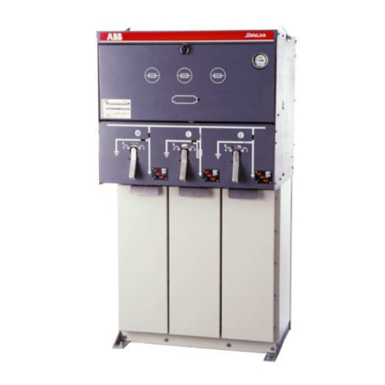
Page 11: Figure 6: Front Of Safelink Unit Showing The Mimic Diagram And Switches In
The operating handle has been designed to give a delay between operations either clockwise or anti-clockwise. Figure 6: Front of SafeLink unit showing the mimic diagram and switches in (from left to right) the off, on, and earth positions. -
Page 12: Switch-Fuse Reset
Rotate the fuse access door catch anti- clockwise to open. Figure 7: Front of SafeLink unit showing the mimic diagram for the switch-fuse following a fuse blow event. Note the word ‘RESET’ and the red fuse blown indicator are displayed. -
Page 13: Figure 9: Central Fuse Assembly And Fuse Being Withdrawn
Carefully refit the fuse and fuse assembly into the canister. Do not overtighten the clamp screw. Figure 10: Fuse canister after fuse assembly and fuse have been removed. SLMIO ver 2.12 ABB Ltd, Switchgear Division, Auckland, New Zealand... -
Page 14: Fuse Link Selection
DIN 43625. Fuse links are to comply to IEC 60282-1 with ‘medium’ striker energy, e.g. ABB CEF range or equivalent. The SafeLink has been heat run tested to IEC 60298 under two conditions: with 400A and 630A maximum ring circuit currents. Under these conditions the maximum continuous heat dissipation from each fuse canister is 58W and 47W respectively. -
Page 15: Cable Box
Cable testing should be carried out in accordance with the cable manufacturer’s recommended practice. It is important that the terminations be done in the manner outlined in section 5.3 on page 14. SLMIO ver 2.12 ABB Ltd, Switchgear Division, Auckland, New Zealand... -
Page 16: Maintenance
The SafeLink switching enclosure is a gas-tight welded stainless steel compartment able to withstand a harsh environment. However, it is important that the base of the SafeLink installation be kept free of vegetation or other material to prevent corrosion of the stand and/or enclosure. -
Page 17: Transport & Handling
The units are supplied packed on a pallet or concrete pad to allow forkhoist movement. Lifting eyes are also provided as standard. Where the unit is supplied with an enclosure this is generally supplied as a flat-pack to be fitted to the SafeLink following installation. -
Page 18: Installation
The equipment shall be mounted on a concrete base designed to support the equipment weight of 250kg, plus 80kg for the outdoor enclosure if used. ABB is able to supply a suitable concrete base as an optional item. The base pad shall be mounted on a prepared and compacted base. -
Page 19: Steps For Cable Connection
Avoid dirt on the rubber plug; do not apply grease. The fuse canister and tripping mechanism must be kept clean and dry. Discard and replace all three fuses when any fuse has operated (refer to IEC 60282-1 & IEC 60420). SLMIO ver 2.12 ABB Ltd, Switchgear Division, Auckland, New Zealand... -
Page 20: Outdoor Enclosure
4mm allen key are needed. Once installed all critical fixings are hidden. For access to the SafeLink unit, the top lifts up, and the door is hinged on the left. The enclosure is supplied in a flat-pack form for retrofitting. Full instructions for assembly and mounting are supplied with each enclosure.