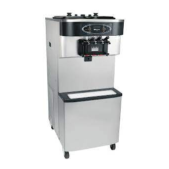
Taylor C712 Operating Instructions Manual
Soft serve freezer
Hide thumbs
Also See for C712:
- Service manual (106 pages) ,
- Service manual (120 pages) ,
- Operator training (41 pages)

Related Manuals for Taylor C712


Summary of Contents for Taylor C712
- Page 1 Model C712 Soft Serve Freezer Original Operating Instructions 062179- M 2/03/05 (Original Publication) Updated 5/20/13...
- Page 2 Minimum Wire Ampacity: E February, 2005 Taylor All rights reserved. 062179--M Taylor Company The word Taylor and the Crown design 750 N. Blackhawk Blvd. are registered trademarks in the United States Rockton, IL 61072 of America and certain other countries.
-
Page 3: Table Of Contents
............Model C712 Door and Beater Assembly . - Page 4 E February, 2005 Taylor (Original Printing) Updated May, 2013 All rights reserved. 062179-M Taylor Company The word Taylor and the Crown design 750 N. Blackhawk Blvd. are registered trademarks in the United States Rockton, IL 61072 of America and certain other countries.
-
Page 5: To The Installer
Please contact your local authorities if you have any questions. The Model C712 air cooled unit requires a minimum Care should be taken to ensure that all basic safety of 3” (76 mm) of clearance on all sides. Install the... -
Page 6: Water Connections (Water Cooled Units Only)
If the supply cord is damaged, it must be replaced Refer to the wiring diagram provided inside the by the manufacturer, its service agent, or similarly electrical box, for proper power connections. qualified person, in order to avoid a hazard. 130304 To the Installer Model C712... -
Page 7: Beater Rotation
To correct the rotation on a three-phase unit, interchange any two incoming power supply lines at Taylor reminds technicians to be cautious of freezer main terminal block only. government laws regarding refrigerant recovery, To correct rotation on a single-phase unit, change recycling, and reclaiming systems. -
Page 8: To The Operator
Taylor parts, purchased from an technician he employs. authorized Taylor Distributor, and the required It should also be noted that Taylor does not warrant service work is provided by an authorized Taylor the refrigerant used in its equipment. For example, if service technician. -
Page 9: Safety
Section 3 Safety We at Taylor are concerned about the safety of the operator when he or she comes in contact with the freezer and its parts. Taylor has gone to extreme efforts to design and manufacture built-in safety DO NOT operate the freezer unless it is features to protect both you and the service properly grounded. - Page 10 78 dB(A) when measured at a distance of experience with the appliance, in particular as far as 1.0 meter from the surface of the machine and at a safety and hygiene are concerned. height of 1.6 meters from the floor. 130304 Safety Model C712...
-
Page 11: Operator Parts Identification
Section 4 Operator Parts Identification Model C712 Figure 1 121022 Model C712 Operator Parts Identification... - Page 12 C712 Exploded View Parts Identification ITEM DESCRIPTION PART NO. ITEM DESCRIPTION PART NO. COVER-HOPPER 053809-1 PANEL-SIDE-RIGHT 063087 PUMP A.-MIX SIMPLIFIED X57029-14 DEFLECTOR-BLOWER 047912 PANEL-REAR 064258-SER CASTER-4” SWV 3/4-10 STEM 046437 W/BRAKE PAN-DRIP 7.875 059737 PANEL A.-FRONT LOWER X59854-SER PANEL-SIDE*RIGHT 059907 SHIELD-SPLASH-WIRE-19-3/4 L 033813 PAN-DRIP 12.5...
-
Page 13: Model C712 Door And Beater Assembly
Model C712 Door and Beater Assembly Figure 2 ITEM DESCRIPTION PART NO. ITEM DESCRIPTION PART NO. HANDLE A.-DRAW-WELDED X56421-1 BEARING-FRONT-SHOE 050348 PLUG-PRIME TWIN 059936 SHOE-FRONT HELIX *REAR 050346 NUT-STUD-BLACK 3.250 L 058765 SHOE-FRONT HELIX *FRONT 050347 NUT-STUD-BLACK 2.563 L 058764 BEATER A.-3.4QT-1 PIN... -
Page 14: X57029-Xx Pump A. - Mix Simplified
*NOTE: THE STANDARD PUMP X57029-XX IS -14. OVERRUN CAN BE CHANGED HIGHER OR LOWER BY SUBSTITUTING THE CAP (056874-XX) WITH CAPS AVAILABLE -1 THROUGH -20. THE HIGHER THE DASH (-) NUMBER, THE HIGHER THE OVERRUN. 121022 Operator Parts Identification Model C712... -
Page 15: Accessories
KIT A.-TUNE-UP X49463-81 HOPPER *Note: A sample container of sanitizer is sent with the unit. For reorders, order Stera Sheen part no. 055492 (100 packs) or Kay-5 part no. 041082 (125 packs). **Not Shown 081120 Model C712 Operator Parts Identification... -
Page 16: Brushes
DESCRIPTION PART NO. BLACK BRISTLE BRUSH 013071 WHITE BRISTLE BRUSH 023316 (3” x 7”) DOUBLE END BRUSH 013072 BRUSH-END-DOOR-SPOUT 039719 WHITE BRISTLE BRUSH 013073 (1” x 2”) BRUSH-PUMP SPOUT 054068 BRUSH SET (3) 050103 121022 Operator Parts Identification Model C712... -
Page 17: Important: To The Operator
Figure 6 ITEM DESCRIPTION ITEM DESCRIPTION POWER SWITCH SELECT KEY FLUORESCENT DISPLAY SERVICE MENU KEY KEYPADS BRUSH CLEAN COUNTER MIX OUT INDICATOR ARROW KEYS STANDBY KEY SYRUP TOPPING HEATER KEY MIX LOW INDICATOR 130220 Model C712 Important: To the Operator... -
Page 18: Symbol Definitions
To better communicate in the International arena, symbols have replaced words on many of our operator switches, function, and fault indicators. Your Taylor equipment is designed with these Power Switch International symbols. When placed in the ON position, the power switch allows control panel operation. -
Page 19: Operating Screen Descriptions
10 seconds. To INCREASE the flow rate, tighten the screw. To DECREASE the See “NVRAM FAULT” for instructions if the above flow rate, loosen the screw. (See Figure 7.) message appears on the screen. 081205 Model C712 Important: To the Operator... -
Page 20: Manager's Menu
Note: The machine will continue operation in the mode it was in when the Menu was selected. However, the control keys will not be illuminated and are non-functional when the Manager's Menu is Figure 11 displayed. 050722 Important: To the Operator Model C712... - Page 21 The SERVING COUNTER will automatically reset to zero when the machine is brush cleaned. (See Figure 15.) SERVINGS COUNTER > Next Figure 14 Figure 15 050722 Model C712 Important: To the Operator...
- Page 22 SEL symbol to select the Change option. (See also be Disabled and require starting the AUTO Figure 18.) mode manually. (See Figure 21.) SET CLOCK AUTO START TIME 12:01 7/15/2004 DISABLED Change Enable > Exit > Disable Figure 18 Figure 21 Important: To the Operator Model C712...
- Page 23 Menu screen. Discontinue Standby operation by exiting the Manager's Menu and select the AUTO mode. (See Figure 24.) STANDBY MODE > EXIT Figure 24 Model C712 Important: To the Operator...
- Page 24 (See Figure 28.) BARREL THERMISTOR BAD - Place the power switch in the OFF position. Call service technician. SOFTWARE VERSION The FAULT HISTORY screen displays a history of C712 CONTROL UVC3 the faults. (See Figure 27.) VERSION 1.04 > Next FAULT HISTORY...
-
Page 25: Operating Procedures
Section 6 Operating Procedures The C712 machine stores mix in a hopper. It has Step 4 two 3.4 quart (3.2 liter) capacity freezing cylinders Apply an even coat of lubricant to the shaft. DO NOT lubricate the hex end. (See Figure 31.) with a three spout door. - Page 26 Holding the rear blade on the beater, slide it into the freezing cylinder halfway. Install the front scraper blade over the front holding pin. (See Figure 34.) Figure 36 Repeat these steps for the other side of the Figure 34 machine. Operating Procedures Model C712...
- Page 27 DO NOT lubricate the gaskets or front bearings. Slide the two o-rings into the grooves on each prime plug. Apply an even coat of Taylor Lube to the o-rings and shafts. Figure 40 With the door seated on the freezer studs, install the handscrews.
- Page 28 Slide the fork of each draw Lubricate the inside of the freezer door spouts, top handle into the slot of each draw valve, starting from and bottom. the right. Figure 42 Figure 44 Operating Procedures Model C712...
- Page 29 213 g.) of product by weight per 10 seconds. the side panels. (See Figure 48.) To INCREASE the flow rate, tighten the screw. To DECREASE the flow rate, loosen the screw. Figure 46 Figure 48 081205 Model C712 Operating Procedures...
-
Page 30: Mix Pump Assembly
DO NOT lubricate the o-ring. Assemble the valve cap. Slide the o-ring into the (See Figure 50.) groove of the valve cap. DO NOT lubricate the o-ring. (See Figure 53.) Figure 50 Figure 53 Operating Procedures Model C712... - Page 31 Assemble the feed tube assembly. Slide the check ring into the groove of the feed tube. (See Figure 58.) Figure 55 Step 8 Insert the mix inlet assembly into the pump cylinder. (See Figure 56.) Figure 56 Figure 58 121022 Model C712 Operating Procedures...
-
Page 32: Sanitizing
(See Figure 60.) Step 2 Pour sanitizing solution over all the parts in the bottom of the mix hopper and allow it to flow into the freezing cylinder. (See Figure 62.) Figure 60 Figure 62 080908 Operating Procedures Model C712... - Page 33 Failure to sanitizing solution in the freezing cylinder to be follow this instruction could result in sanitizer agitated. Wait at least 5 minutes before proceeding spraying on the operator. (See Figure 64.) with these instructions. 121022 Model C712 Operating Procedures...
-
Page 34: Priming
ALWAYS FOLLOW LOCAL HEALTH CODES. Repeat these steps for the other side of the machine. To disassemble the Model C712, the following items will be needed: Note: Be sure your hands are clean and Two cleaning and sanitizing pails sanitized before going on in these instructions. -
Page 35: Hopper Cleaning
Using the double ended brush, clean the mix inlet hole. (Note: Do not brush clean the mix inlet hole while the machine is in Figure 66 the Wash mode.) 080908 Model C712 Operating Procedures... -
Page 36: Disassembly
Once the cleaning solution stops flowing from the door spout, close the draw valve and the prime plug. Step 9 Touch the WASH symbol , cancelling the Wash mode. Repeat these steps on the other side of the machine. Figure 68 Operating Procedures Model C712... -
Page 37: Brush Cleaning
Rinse all parts with clean, warm water. Place the Note: The brush clean counter will reset to zero at parts on a clean, dry surface to air dry overnight. this time. 080908 Model C712 Operating Procedures... -
Page 38: Important: Operator Checklist
Deteriorated or cracked water lines should be j 6. The temperature of mix in the mix hopper and replaced only by an authorized Taylor walk-in cooler should be below 40_F (4.4_C). distributor. 080107 Important: Operator Checklist... -
Page 39: Winter Storage
Winter Storage If the place of business is to be closed during the Your local Taylor Distributor can perform this winter winter months, it is important to protect the freezer storage service for you. by following certain precautions, particularly if the Wrap detachable parts of the freezer such as building is subject to freezing conditions. -
Page 40: Troubleshooting Guide
2. The product is too soft. a. Draw rate is set too fast. a. Adjust draw rate of 5 to 7 1/2 oz. (142 g. to 213 g.) of product by weight in 10 seconds. Important: Operator Checklist Model C712... - Page 41 - - - technician. assembly work forward. e. Worn rear shell bearing. e. Call an authorized service - - - technician. f. Gear box out of alignment. f. Call an authorized service - - - technician. Model C712 Important: Operator Checklist...
- Page 42 Machine is unplugged. a. Plug into wall receptacle. - - - with power switch ON. b. Circuit breaker OFF or b. Turn the breaker ON or - - - replace the fuse. blown fuse. Important: Operator Checklist Model C712...
-
Page 43: Parts Replacement Schedule
Inspect & Replace Minimum if Necessary Black Bristle Brush, 1” x 2” Inspect & Replace Minimum if Necessary Double-Ended Brush Inspect & Replace Minimum if Necessary Brush Set (3) Inspect & Replace Minimum if Necessary Model C712 Parts Replacement Schedule... -
Page 44: Warranty Explanation
Taylor Distributor, and the required service work is provided by an authorized Taylor service technician. Taylor reserves the right to deny warranty claims on equipment or parts if non-approved parts or refrigerant were installed in the machine, system modifications were performed beyond factory recommendations, or it is determined that the failure was caused by neglect or abuse. -
Page 45: Parts List
Section 11 Parts List 100901 Model C712 Parts List... - Page 46 Parts List Model C712...
- Page 47 Model C712 Parts List...
- Page 48 Parts List Model C712...
- Page 49 Model C712 Parts List...
- Page 50 121022 Parts List Model C712...
- Page 51 Model C712 Parts List...
- Page 52 100930 Parts List Model C712...
- Page 53 Model C712 Parts List...
- Page 54 Model C712 059898-27 5/13...
- Page 55 Model C712 059898-33 5/13...
- Page 56 Model C712 059898-40 5/13...
- Page 57 Model C712 059898-58 5/13...
Need help?
Do you have a question about the C712 and is the answer not in the manual?
Questions and answers